technical data Seat Altea 2010 Owner's Manual
[x] Cancel search | Manufacturer: SEAT, Model Year: 2010, Model line: Altea, Model: Seat Altea 2010Pages: 310, PDF Size: 7.46 MB
Page 261 of 310
If and when259
Safety First
Operating instructions
Practical tips
Technical Data
– Insert the adapter onto the wheel bolt and push it on as far as it
will go ⇒page 258, fig. 181.
– Fit the box spanner as far as it will go over the adapter.
– Loosen or tighten the wheel bolt as appropriate.Error code
The code number of the anti-theft wheel bolt is stamped onto the front part of
the adaptor.
The code number should be noted and kept in a safe place, as it is only by
using the code number that a duplicate adaptor can be obtained from an
Authorised Service Centre.Tyres with directional tread pattern
Tyres with directional tread pattern must be fitted so that they
rotate in the correct direction.A directional tread pattern can be identified by arrows on the sidewall that
point in the direction of rotation. Always note the direction of rotation indi-
cated when fitting the wheel. This is important so that these tyres can give
maximum grip and avoid excessive noise, tread wear and aquaplaning.
If, in an emergency, you have to fit the spare wheel so it rotates in the wrong
direction, you must drive extremely carefully. The tyre will not give optimum
performance. This is particularly im portant when driving on wet roads.
To benefit from the advantages of tyres with this type of tread pattern, the
defective tyre should be replaced as soon as possible so that all tyres again
rotate in the correct direction.
Tyre repair kit* (Tyre Mobility System)General information and safety notesYour vehicle is equipped with a tyre repair kit: the Tyre Mobility System.
In the event of a tyre puncture, a sealing compound and an air compressor are
located in the luggage compartment under the floor panel.
The Tyre Mobility System will reliably seal punctures caused by the penetra-
tion of a foreign body of up to about 4 mm in diameter.
It is not necessary to remove the foreign body from the tyre.
Instructions for the sealing compound are located on the sealing compound
container.
Notes for the proper use of the air compressor are included in an additional
instruction leaflet.
WARNING
•Do not attempt to repair a puncture with the sealing compound if the
tyre has been damaged by driving the car after the tyre has lost its air.•Always observe warnings and follow instructions concerning
compressor and sealing compound carefully.•Do not drive faster than 80 km/h, avoid heavy acceleration, hard
braking and fast cornering.•Tyres which have been repaired with sealing compound are only suit-
able for temporary use over a short period. Therefore, please drive carefully
to the next available qualified workshop.For the sake of the environment
Used sealing compound containers should be disposed of at a proper facility.
altea_EN Seite 259 Mittwoch, 26. August 2009 6:00 18
Page 263 of 310
If and when261
Safety First
Operating instructions
Practical tips
Technical Data
Completing th e repa ir
– Remove the compressor hose from the valve.
–Fit the valve cap.
– Unplug the compressor from the socket.
– Return all tools to their proper storing location.
Note•If the vehicle is equipped with tyre pressure control, enter the new tyre
pressures using the SET button on the central console.•The compressor should never be allowed to run for longer than 6
minutes.
FusesChanging a fuse
Blown fuses must be replaced
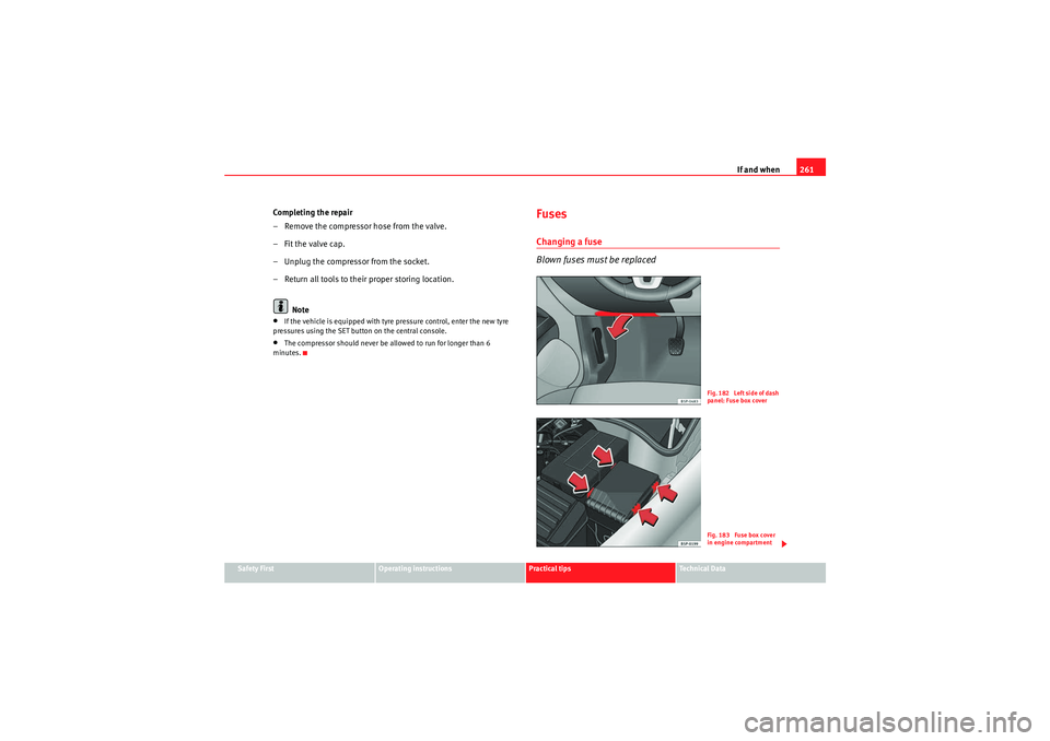
Fig. 182 Left side of dash
panel: Fuse box coverFig. 183 Fuse box cover
in engine compartment
altea_EN Seite 261 Mittwoch, 26. August 2009 6:00 18
Page 265 of 310
If and when263
Safety First
Operating instructions
Practical tips
Technical Data
•Apart from the fuses indicated in the following tables, there are others
which must be replaced by a Technical Service.
altea_EN Seite 263 Mittwoch, 26. August 2009 6:00 18
Page 267 of 310
If and when265
Safety First
Operating instructions
Practical tips
Technical Data
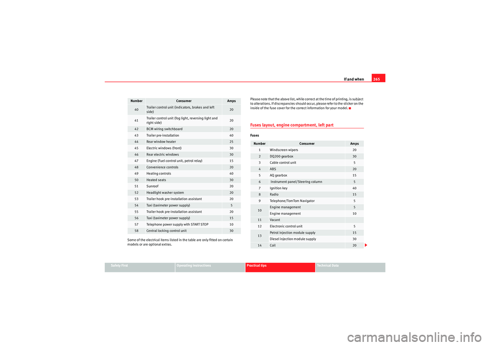
Some of the electrical items listed in the table are only fitted on certain
models or are optional extras. Please note that the above list, while correct at the time of printing, is subject
to alterations. If discrepancies should occur, please refer to the sticker on the
inside of the fuse cover for the correct information for your model.
Fuses layout, engine compartment, left partFuses
40
Trailer control unit (indicators, brakes and left
side)
20
41
Trailer control unit (fog light, reversing light and
right side)
20
42
BCM wiring switchboard
20
43
Trailer pre-installation
40
44
Rear window heater
25
45
Electric windows (front)
30
46
Rear electric windows
30
47
Engine (Fuel control unit, petrol relay)
15
48
Convenience controls
20
49
Heating controls
40
50
Heated seats
30
51
Sunroof
20
52
Headlight washer system
20
53
Trailer hook pre-installation assistant
20
54
Taxi (taximeter power supply)
5
55
Trailer hook pre-installation assistant
20
56
Taxi (taximeter power supply)
15
57
Telephone power supply with START STOP
10
58
Central locking control unit
30
Number
Consumer
Amps
Number
Consumer
Amps
1
Windscreen wipers
20
2
DQ200 gearbox
30
3
Cable control unit
5
4
ABS
20
5
AQ gearbox
15
6
Instrument panel/Steering column
5
7
Ignition key
40
8
Radio
15
9
Telephone/TomTom Navigator
5
10
Engine management
5
Engine management
10
11
Vaca nt
12
Electronic control unit
5
13
Petrol injection module supply
15
Diesel injection module supply
30
14
Coil
20
altea_EN Seite 265 Mittwoch, 26. August 2009 6:00 18
Page 269 of 310
If and when267
Safety First
Operating instructions
Practical tips
Technical Data
Fog lights
Fog lights - H3
Upper rear light
Stop/Position - P21W
26)
Indicator - R10W
Lower rear light
Fog light - P21W
Reverse light - P21W
Side indicator
Side indicator - W5W
Registration plate light
Registration plate light - C5W
Note
•Depending on weather conditions (cold or wet), the front lights, the fog
lights, the rear lights and the indicators may be temporarily misted. This has
no influence on the life expectancy of the lighting system. By switching on the
lights, the area through which the beam of light is projected will quickly be
demisted. However, the edges may continue to be misted.•Please check at regular intervals that all lighting (especially the exterior
lighting) on your vehicle is functioning properly. This is not only in the interest
of your own safety, but also in that of all other road users.•Due to the difficulty in accessing the lamps, any replacement work should
be done by a SEAT dealer. However, the following is a description of how to
change the lamps except for the fog lights* and interior lamps.
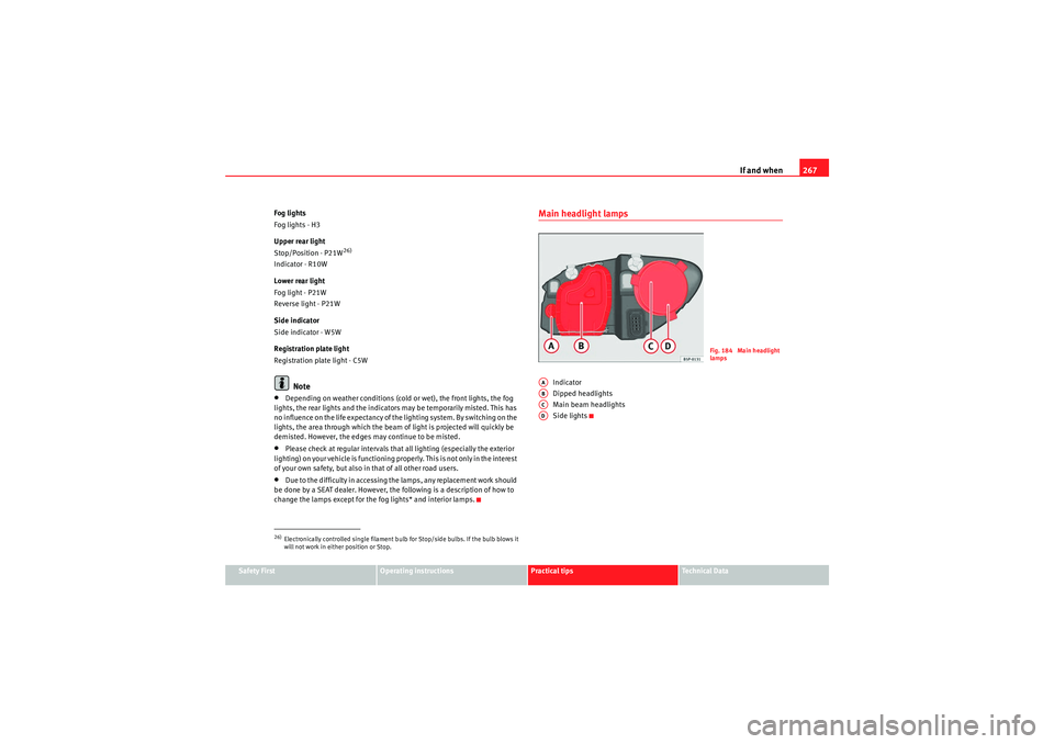
Main headlight lamps
Indicator
Dipped headlights
Main beam headlights
Side lights
26)Electronically controlled single filament bulb for Stop/side bulbs. If the bulb blows it
will not work in either position or Stop.
Fig. 184 Main headlight
lamps
AAABACAD
altea_EN Seite 267 Mittwoch, 26. August 2009 6:00 18
Page 271 of 310
If and when269
Safety First
Operating instructions
Practical tips
Technical Data
– Remove the loops ⇒page 268, fig. 186 in the direction of
the arrow and remove the cover.
– Remove the connector ⇒page 268, fig. 187 from the bulb.
– Disengage the retainer spring ⇒page 268, fig. 187 pressing
inwards to the right.
– Extract the bulb and fit the replacement so that the rim of the attachment plate is on the reflector cut-out.Main beam lights
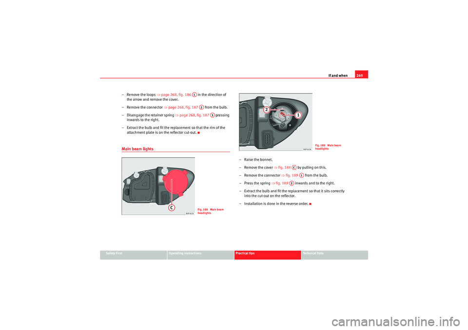
– Raise the bonnet.
– Remove the cover ⇒ fig. 188 by pulling on this.
– Remove the connector ⇒fig. 189 from the bulb.
– Press the spring ⇒fig. 189 inwards and to the right.
– Extract the bulb and fit the replacement so that it sits correctly into the cut-out on the reflector.
– Installation is done in the reverse order.
A1A2
A3
Fig. 188 Main beam
headlights
Fig. 189 Main beam
headlights
AC
A1
A2
altea_EN Seite 269 Mittwoch, 26. August 2009 6:00 18
Page 273 of 310

If and when271
Safety First
Operating instructions
Practical tips
Technical Data
Side lights and brake lights– Open the tailgate.
– Remove the bolts ⇒ fig. 192 . – Remove the cover of the luggage compartment lateral panel.
– Unscrew the plastic fitting
⇒fig. 193 securing the rear light.
Inserting a screwdriver under th e plastic fitting may help to
loosen it.
– Partially remove the rear light from its casing taking care not to pull on the cable.
– Remove the lamp holder connector.
–Unscrew the bolts ⇒page 272, fig. 194 from the lamp holder
and pull on this.
– Press on the lamp and rotate to the left then fit the replacement.
– To refit follow the steps in reverse order, taking special care when fitting the lamp holder. The metal contacts of the lamp holder
ends should be correctly fitted with respect to the rear light
contacts.
Fig. 192 Side lights and
brake lightsFig. 193 Side lights and
brake lights
AA
ABAC
altea_EN Seite 271 Mittwoch, 26. August 2009 6:00 18
Page 275 of 310
If and when273
Safety First
Operating instructions
Practical tips
Technical Data
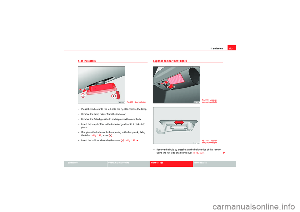
Side indicators– Press the indicator to the left or to the right to remove the lamp.
– Remove the lamp holder from the indicator.
– Remove the failed glass bulb and replace with a new bulb.
– Insert the lamp holder in the indicator guide until it clicks into
place.
– First place the indicator in th e opening in the bodywork, fixing
the tabs ⇒ fig. 197, arrow .
– Insert the bulb as shown by the arrow ⇒fig. 197 .
Luggage compartment lights– Remove the bulb by pressing on the inside edge of this -arrow-
using the flat side of a screwdriver ⇒fig. 198 .
Fig. 197 Side indicator
A1
A2
Fig. 198 Luggage
compartment lightFig. 199 Luggage
compartment light
altea_EN Seite 273 Mittwoch, 26. August 2009 6:00 18
Page 277 of 310
If and when275
Safety First
Operating instructions
Practical tips
Technical Data
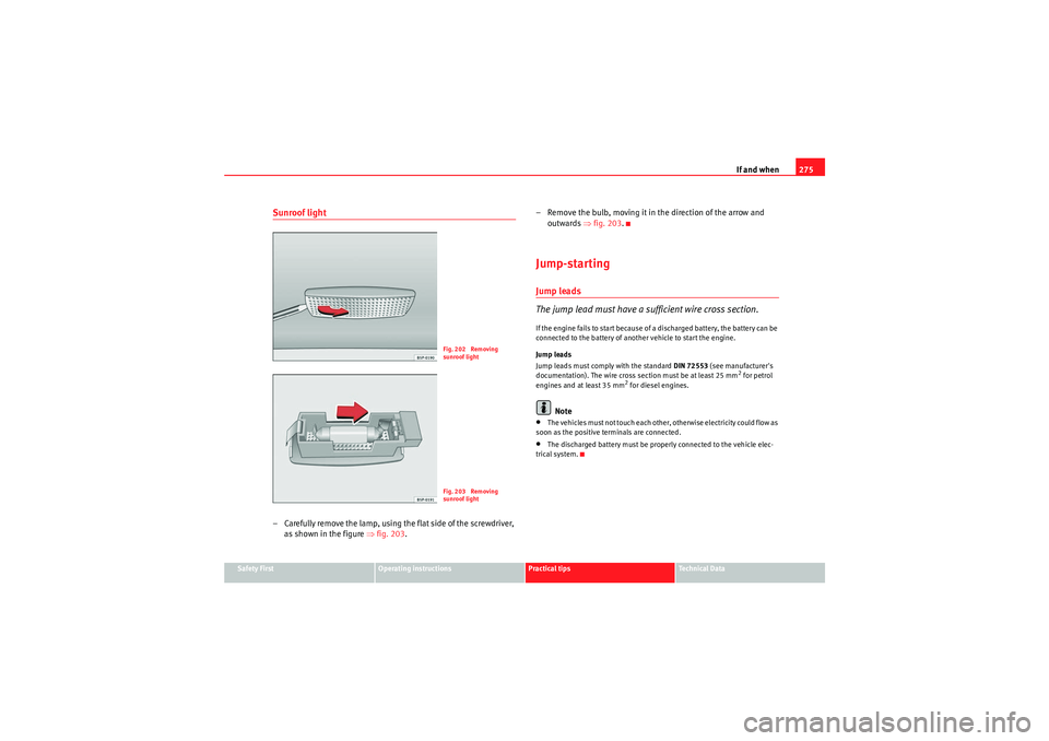
Sunroof light– Carefully remove the lamp, using the flat side of the screwdriver,
as shown in the figure ⇒fig. 203 . – Remove the bulb, moving it in the direction of the arrow and
outwards ⇒fig. 203 .
Jump-startingJump leads
The jump lead must have a sufficient wire cross section.If the engine fails to start because of a discharged battery, the battery can be
connected to the battery of another vehicle to start the engine.
Jump leads
Jump leads must comply with the standard DIN 72553 (see manufacturer's
documentation). The wire cross section must be at least 25 mm
2 for petrol
engines and at least 35 mm
2 for diesel engines.
Note
•The vehicles must not touch each other, otherwise electricity could flow as
soon as the positive terminals are connected.•The discharged battery must be properly connected to the vehicle elec-
trical system.
Fig. 202 Removing
sunroof lightFig. 203 Removing
sunroof light
altea_EN Seite 275 Mittwoch, 26. August 2009 6:00 18
Page 279 of 310
If and when277
Safety First
Operating instructions
Practical tips
Technical Data
WARNING
•Please note the safety warnings referring to working in the engine
compartment ⇒page 226, “Working in the engine compartment”.•The battery providing assistance must have the same voltage as the flat
battery (12V) and approximately the same capacity (see imprint on
battery). Failure to comply could result in an explosion.•Never use jump leads when one of the batteries is frozen. Danger of
explosion! Even after the battery has thawed, battery acid could leak and
cause chemical burns. If a battery freezes, it should be replaced.•Keep sparks, flames and lighted cigarettes away from batteries, danger
of explosion. Failure to comply could result in an explosion.•Observe the instructions provided by the manufacturer of the jump
leads.•Do not connect the negative cable from the other vehicle directly to the
negative terminal of the flat battery. The gas emitted from the battery could
be ignited by sparks. Danger of explosion.•Do not attach the negative cable from the other vehicle to parts of the
fuel system or to the brake line.•The non-insulated parts of the battery clamps must not be allowed to
touch. The jump lead attached to the positive battery terminal must not
touch metal parts of the vehicle, this can cause a short circuit.•Position the leads in such a way that they cannot come into contact
with any moving parts in the engine compartment.•Do not bend over the batteries. This could result in chemical burns.Note
The vehicles must not touch each other, otherwise electricity could flow as
soon as the positive terminals are connected.
altea_EN Seite 277 Mittwoch, 26. August 2009 6:00 18