technical specifications Seat Altea 2013 Repair Manual
[x] Cancel search | Manufacturer: SEAT, Model Year: 2013, Model line: Altea, Model: Seat Altea 2013Pages: 315, PDF Size: 4.66 MB
Page 125 of 315
123
Lights and visibility
Turn signal and main beam headlight lever
The turn signal and main beam lever also operates the park-
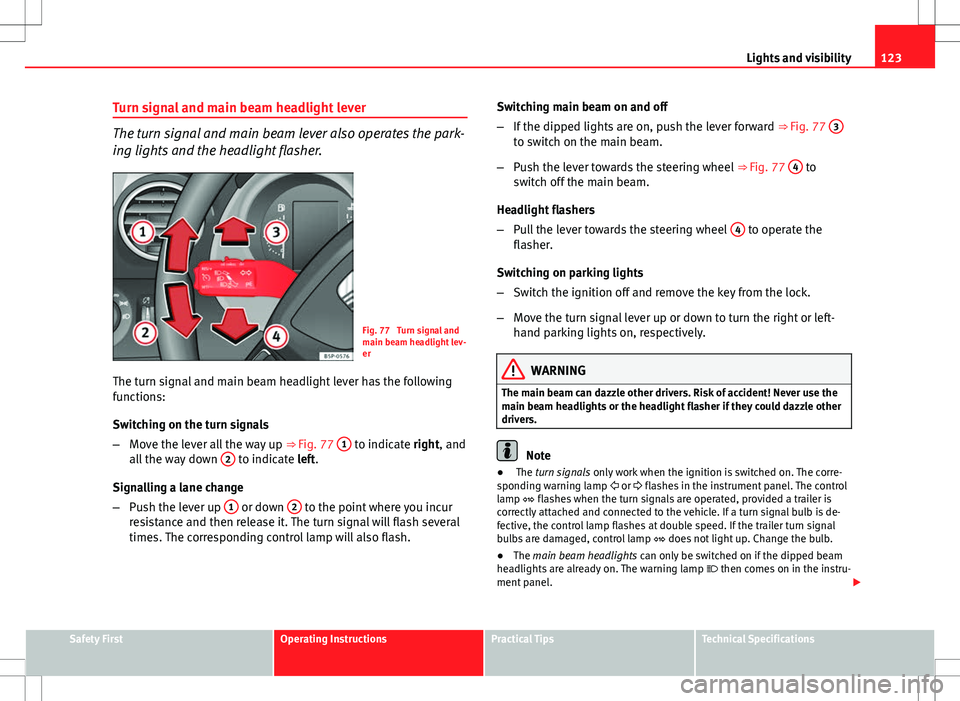
ing lights and the headlight flasher.
Fig. 77 Turn signal and
main beam headlight lev-
er
The turn signal and main beam headlight lever has the following
functions:
Switching on the turn signals
– Move the lever all the way up ⇒ Fig. 77 1
to indicate right, and
all the way down 2 to indicate left.
Signalling a lane change
– Push the lever up 1
or down 2 to the point where you incur
resistance and then release it. The turn signal will flash several
times. The corresponding control lamp will also flash. Switching main beam on and off
–
If the dipped lights are on, push the lever forward ⇒ Fig. 77 3
to switch on the main beam.
– Push the lever towards the steering wheel ⇒ Fig. 77 4
to
switch off the main beam.
Headlight flashers
– Pull the lever towards the steering wheel 4
to operate the
flasher.
Switching on parking lights
– Switch the ignition off and remove the key from the lock.
– Move the turn signal lever up or down to turn the right or left-
hand parking lights on, respectively.
WARNING
The main beam can dazzle other drivers. Risk of accident! Never use the
main beam headlights or the headlight flasher if they could dazzle other
drivers.
Note
● The turn signals only work when the ignition is switched on. The corre-
sponding warning lamp or flashes in the instrument panel. The control
lamp flashes when the turn signals are operated, provided a trailer is
correctly attached and connected to the vehicle. If a turn signal bulb is de-
fective, the control lamp flashes at double speed. If the trailer turn signal
bulbs are damaged, control lamp does not light up. Change the bulb.
● The main beam headlights can only be switched on if the dipped beam
headlights are already on. The warning lamp then comes on in the instru-
ment panel.
Safety FirstOperating InstructionsPractical TipsTechnical Specifications
Page 127 of 315
125
Lights and visibility
Interior front light, type 2
Fig. 79 Interior roof trim:
front interior lighting
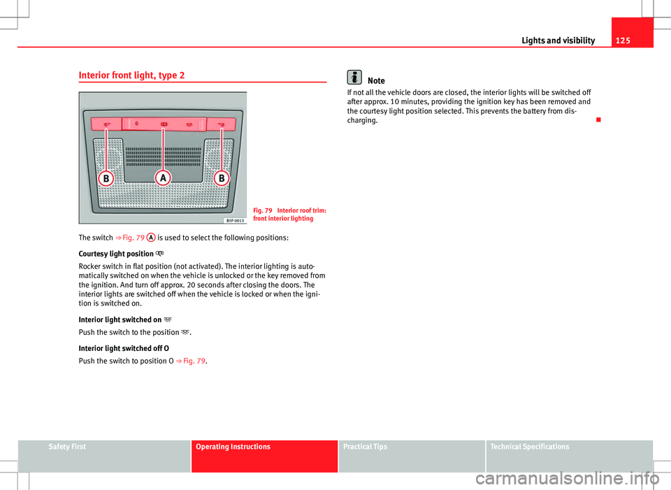
The switch ⇒ Fig. 79 A
is used to select the following positions:
Courtesy light position
Rocker switch in flat position (not activated). The interior lighting is auto-
matically switched on when the vehicle is unlocked or the key removed from
the ignition. And turn off approx. 20 seconds after closing the doors. The
interior lights are switched off when the vehicle is locked or when the igni-
tion is switched on.
Interior light switched on
Push the switch to the position .
Interior light switched off O
Push the switch to position O ⇒ Fig. 79.
Note
If not all the vehicle doors are closed, the interior lights will be switched off
after approx. 10 minutes, providing the ignition key has been removed and
the courtesy light position selected. This prevents the battery from dis-
charging.
Safety FirstOperating InstructionsPractical TipsTechnical Specifications
Page 129 of 315
127
Lights and visibility
lights are switched off when the vehicle is locked or when the ignition is
switched on.
Interior lights or both reading lights switched on
Turn the control to position 5
.
Note
If not all the vehicle doors are closed, the interior lights will be switched off
after approx. 10 minutes, providing the ignition key has been removed and
the courtesy light position selected. This prevents the battery from dis-
charging.
Visibility Sun visors
Fig. 83 Sun visor on the
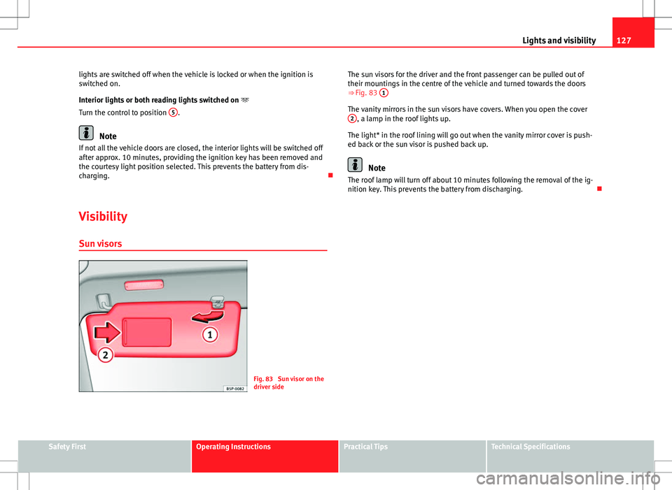
driver side The sun visors for the driver and the front passenger can be pulled out of
their mountings in the centre of the vehicle and turned towards the doors
⇒ Fig. 83
1
The vanity mirrors in the sun visors have covers. When you open the cover
2, a lamp in the roof lights up.
The light* in the roof lining will go out when the vanity mirror cover is push-
ed back or the sun visor is pushed back up.
Note
The roof lamp will turn off about 10 minutes following the removal of the ig-
nition key. This prevents the battery from discharging.
Safety FirstOperating InstructionsPractical TipsTechnical Specifications
Page 131 of 315
129
Lights and visibility
WARNING
● Worn and dirty wiper blades reduce visibility and safety levels while
driving.
● In cold conditions, you should not use the wash/wipe system unless
you have warmed the windscreen with the heating and ventilation sys-
tem. The windscreen washer fluid could otherwise freeze on the
windscreen and obscure your view of the road.
● Always note the corresponding warnings on ⇒ page 243.
CAUTION
In icy conditions, always check that the wiper blades are not frozen to the
glass before using the wipers for the first time. If you switch on the wind-
screen wipers when the wiper blades are frozen to the windscreen, you
could damage both the wiper blades and the wiper motor.
Note
● The windscreen wipers will only work when the ignition is switched on.
● In certain versions of vehicles with alarms, the windscreen wiper will on-
ly work when the ignition is on and the bonnet closed.
● When in use, the wipers do not go as far as the rest position. When the
lever is moved to position 0, they are totally hidden.
● The next speed down will automatically be selected if wiper speed 2
⇒ Fig. 84 or 3 is selected when the vehicle stops. The set speed will be
resumed when the vehicle starts again
● The windscreen will be wiped again after approximately five seconds
once the “automatic wipe/wash system” has been operated, provided the
vehicle is in transit (drip function). If you activate the wipers less than three
seconds after the drip function, a new wash sequence will begin without the
last wipe. For the “drip” function to work again, you have to turn the ignition
off and then on again. ●
When the “interval wipe function” is on, the intervals are directly propor-
tional to the speed. This way, the higher the vehicle speed the shorter the
intervals.
● The wiper will try to wipe away any obstacles that are on the windscreen.
The wiper will stop moving if the obstacle blocks its path. Remove the ob-
stacle and switch the wiper back on again.
● Before removing any objects that may be trapped in the side areas of
the windscreen, always move the wiper arms to the service position (hori-
zontal).
● The heat output of the heated jets is controlled automatically when the
ignition is switched on, depending upon the outside temperature.
Safety FirstOperating InstructionsPractical TipsTechnical Specifications
Page 133 of 315
131
Lights and visibility
Rear window wiper
The windscreen wiper lever operates the windscreen wiper
and the wash and wipe system for the rear window.
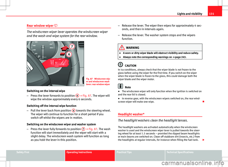
Fig. 87 Windscreen wip-
er and windscreen wash
lever: rear window wiper
Switching on the interval wipe
– Press the lever forwards to position 6
⇒ Fig. 87. The wiper will
wipe the window approximately every 6 seconds.
Switching off the interval wipe function
– Pull the lever back from position 6
towards the steering wheel.
The wiper will continue to function for a short period if you
switch off whilst the wipers are in motion.
Switching on the windscreen wiper and washer system
– Press the lever fully forwards to position 7
⇒ Fig. 87. The wash
function will start immediately and the wiper will start with a
slight delay. The windscreen wash system will function as long
as you hold the lever in this position. –
Release the lever. The wiper then wipes for approximately 4 sec-
onds, and then in intervals again.
– Release the lever. The washer system stops and the wipers
function.
WARNING
● A worn or dirty wiper blade will obstruct visibility and reduce safety.
● Always note the corresponding warnings on ⇒ page 243.
CAUTION
In icy conditions, always check that the wiper blade is not frozen to the
glass before using the wiper for the first time. If you switch on the wiper
when the wiper blade is frozen to the glass, this could damage both the
wiper blade and the wiper motor.
Note
● The windscreen wiper will only function when the ignition is switched on
and the rear lid is closed.
● In reverse gear, with the windscreen wipers switched on, the rear wind-
screen wiper will make one wipe.
Headlight washer*
The headlight washers clean the headlight lenses. The headlight washers are activated automatically when the windscreen
washer is used and the windscreen wiper lever is pulled towards the steer-
ing wheel for at least 1.5 seconds – provided the dipped beam headlights
or main beams are switched on. Clean off stubborn dirt (insects, etc.) from
the headlights at regular intervals, for instance when filling the fuel tank.
Safety FirstOperating InstructionsPractical TipsTechnical Specifications
Page 135 of 315
133
Lights and visibility
Note
● The automatic anti-dazzle function will only work properly if the sun
blind* for the rear window is retracted and there are no other objects pre-
venting light from reaching the interior rear vision mirror.
● If you have to stick any type of sticker on the windscreen, do not do so in
front of the sensors. Doing so could prevent the anti-dazzle function from
working well or even from working at all.
Exterior mirrors
The exterior mirrors can be adjusted using the rotary knob
in the centre console.
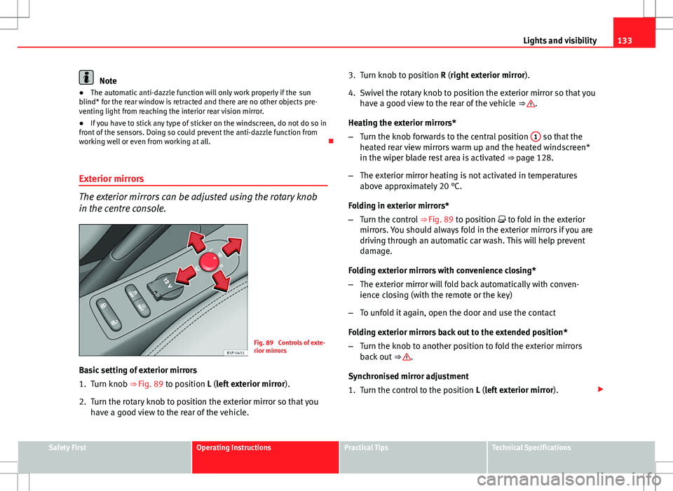
Fig. 89 Controls of exte-
rior mirrors
Basic setting of exterior mirrors
1. Turn knob ⇒
Fig. 89 to position L (left exterior mirror ).
2. Turn the rotary knob to position the exterior mirror so that you have a good view to the rear of the vehicle. 3. Turn knob to position R (right exterior mirror
).
4. Swivel the rotary knob to position the exterior mirror so that you have a good view to the rear of the vehicle ⇒
.
Heating the exterior mirrors*
– Turn the knob forwards to the central position 1
so that the
heated rear view mirrors warm up and the heated windscreen*
in the wiper blade rest area is activated ⇒ page 128.
– The exterior mirror heating is not activated in temperatures
above approximately 20 °C.
Folding in exterior mirrors*
– Turn the control ⇒ Fig. 89 to position to fold in the exterior
mirrors. You should always fold in the exterior mirrors if you are
driving through an automatic car wash. This will help prevent
damage.
Folding exterior mirrors with convenience closing*
– The exterior mirror will fold back automatically with conven-
ience closing (with the remote or the key)
– To unfold it again, open the door and use the contact
Folding exterior mirrors back out to the extended position*
– Turn the knob to another position to fold the exterior mirrors
back out ⇒
.
Synchronised mirror adjustment
1. Turn the control to the position L (left exterior mirror).
Safety FirstOperating InstructionsPractical TipsTechnical Specifications
Page 137 of 315
135
Seats and storage
Seats and storage The importance of correct seat adjustment
Proper seat adjustment optimises the level of protection of-
fered by seat belts and airbags.
Your vehicle has five seats, two in the front and three in the rear. Each seat
is equipped with a three-point seat belt.
The driver seat and the front passenger seat can be adjusted in many ways
to suit the physical requirements of the vehicle occupants. The correct seat
position is very important for:
● a fast and easy operation of all controls on the instrument panel,
● a relaxed posture which does not cause drowsiness,
● a safe driving ⇒ page 7,
● ensuring that the seat belts and airbag system provide maximum pro-
tection ⇒ page 19.
WARNING
● If the driver and passengers assume improper sitting positions, they
may sustain critical injuries.
● Never transport more than the permitted amount of people in your ve-
hicle.
● Every vehicle occupant must properly fasten and wear the seat belt
belonging to his or her seat. Children must be protected with an appro-
priate child restraint system ⇒ page 46, Child safety.
● The front seats and all head restraints must always be adjusted to
body size and the seat belt must always be properly adjusted to provide
you and your passengers with optimum protection.
WARNING (Continued)
● Always keep your feet on the footwell when the vehicle is moving;
never rest them on the dash panel, out of the window or on the seat. This
is also applied to passengers. An incorrect sitting position exposes you
to an increased risk of injury in case of a sudden braking or an accident.
If the airbag is triggered, you could sustain severe injuries due to an in-
correct sitting position.
● It is important for the driver and front passenger to keep a distance of
at least 25 cm from the steering wheel and dash panel. Failure to respect
the minimum distance means that the airbag will not protect you. Risk of
fatal injury. The distance between the driver and the steering wheel or
between the front passenger and the dash panel should always be as
great as possible.
● Adjust the driver or front passenger seat only when the vehicle is sta-
tionary. This also applies to the forwards/backwards adjustment of the
rear seats. Otherwise, your seat could move unexpectedly while the vehi-
cle is moving. This could increase the risk of an accident and therefore,
injury. In addition, while adjusting your seat, you will assume an incor-
rect sitting position. Risk of fatal accidents.
● Special guidelines apply to installing a child seat on the front passen-
ger seat. When installing a child seat, please observe the warnings de-
scribed in ⇒ page 46, Child safety.
Safety FirstOperating InstructionsPractical TipsTechnical Specifications
Page 139 of 315
137
Seats and storage
Removing or adjusting head restraints
The head restraints can be adjusted by moving them up and
down.
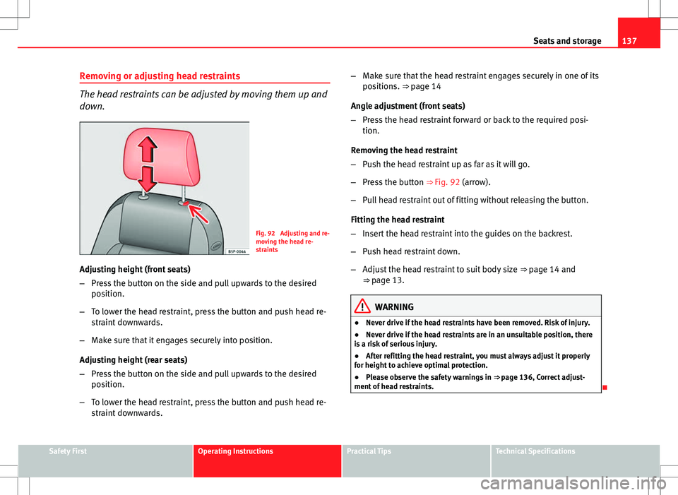
Fig. 92 Adjusting and re-
moving the head re-
straints
Adjusting height (front seats)
– Press the button on the side and pull upwards to the desired
position.
– To lower the head restraint, press the button and push head re-
straint downwards.
– Make sure that it engages securely into position.
Adjusting height (rear seats)
– Press the button on the side and pull upwards to the desired
position.
– To lower the head restraint, press the button and push head re-
straint downwards. –
Make sure that the head restraint engages securely in one of its
positions. ⇒ page 14
Angle adjustment (front seats)
– Press the head restraint forward or back to the required posi-
tion.
Removing the head restraint
– Push the head restraint up as far as it will go.
– Press the button ⇒ Fig. 92 (arrow).
– Pull head restraint out of fitting without releasing the button.
Fitting the head restraint
– Insert the head restraint into the guides on the backrest.
– Push head restraint down.
– Adjust the head restraint to suit body size ⇒ page 14 and
⇒ page 13.
WARNING
● Never drive if the head restraints have been removed. Risk of injury.
● Never drive if the head restraints are in an unsuitable position, there
is a risk of serious injury.
● After refitting the head restraint, you must always adjust it properly
for height to achieve optimal protection.
● Please observe the safety warnings in ⇒ page 136, Correct adjust-
ment of head restraints.
Safety FirstOperating InstructionsPractical TipsTechnical Specifications
Page 141 of 315
139
Seats and storage
Heated seats*
The front seat cushions and backrests can be heated electri-
cally.
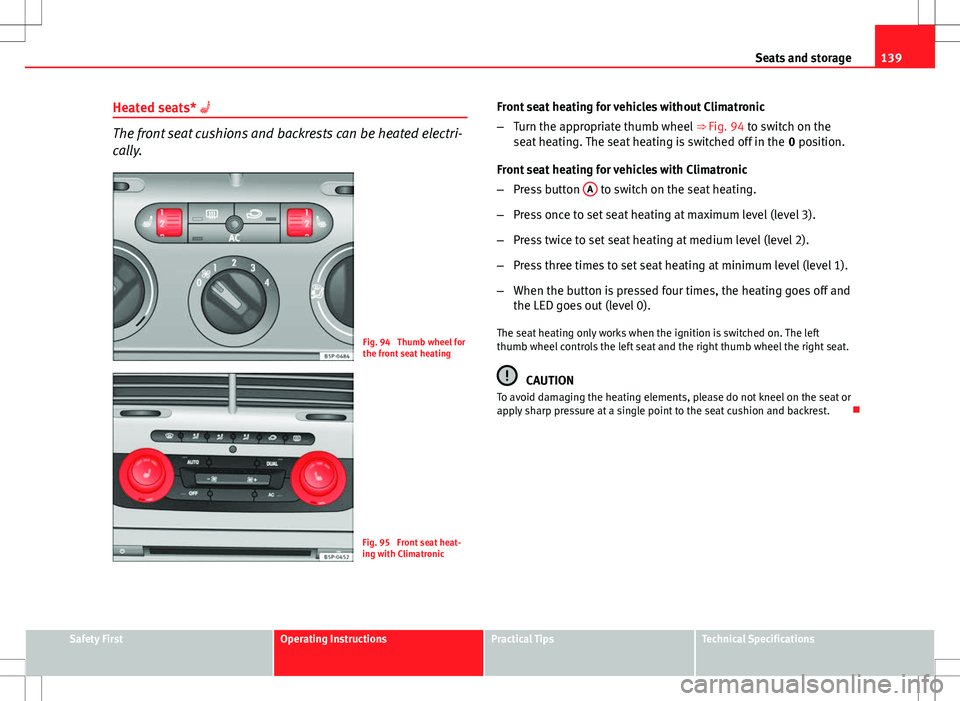
Fig. 94 Thumb wheel for
the front seat heating
Fig. 95 Front seat heat-
ing with Climatronic Front seat heating for vehicles without Climatronic
–
Turn the appropriate thumb wheel ⇒ Fig. 94 to switch on the
seat heating. The seat heating is switched off in the 0 position.
Front seat heating for vehicles with Climatronic
– Press button A
to switch on the seat heating.
– Press once to set seat heating at maximum level (level 3).
– Press twice to set seat heating at medium level (level 2).
– Press three times to set seat heating at minimum level (level 1).
– When the button is pressed four times, the heating goes off and
the LED goes out (level 0).
The seat heating only works when the ignition is switched on. The left
thumb wheel controls the left seat and the right thumb wheel the right seat.
CAUTION
To avoid damaging the heating elements, please do not kneel on the seat or
apply sharp pressure at a single point to the seat cushion and backrest.
Safety FirstOperating InstructionsPractical TipsTechnical Specifications
Page 143 of 315
141
Seats and storage
Folding the seat backrests down
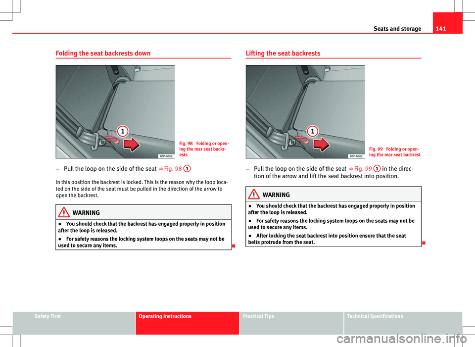
Fig. 98 Folding or open-
ing the rear seat backr-
ests
– Pull the loop on the side of the seat ⇒ Fig. 98 1
In this position the backrest is locked. This is the reason why the loop loca-
ted on the side of the seat must be pulled in the direction of the arrow to
open the backrest.
WARNING
● You should check that the backrest has engaged properly in position
after the loop is released.
● For safety reasons the locking system loops on the seats may not be
used to secure any items.
Lifting the seat backrests
Fig. 99 Folding or open-
ing the rear seat backrest
– Pull the loop on the side of the seat ⇒ Fig. 99 1
in the direc-
tion of the arrow and lift the seat backrest into position.
WARNING
● You should check that the backrest has engaged properly in position
after the loop is released.
● For safety reasons the locking system loops on the seats may not be
used to secure any items.
● After locking the seat backrest into position ensure that the seat
belts protrude from the seat.
Safety FirstOperating InstructionsPractical TipsTechnical Specifications