technical specifications Seat Altea XL 2013 Owner's Manual
[x] Cancel search | Manufacturer: SEAT, Model Year: 2013, Model line: Altea XL, Model: Seat Altea XL 2013Pages: 317, PDF Size: 4.69 MB
Page 259 of 317
257
Wheels and tyres
Winter tyres
Winter tyres will improve the vehicles handling on snow and
ice.
In winter conditions winter tyres will considerably improve the vehicle's han-
dling. The design of summer tyres (width, rubber compound, tread pattern)
gives less grip on ice and snow.
Winter tyres must be inflated to a pressure 0.2 bar higher than the pres-
sures specified for summer tyres (see sticker on fuel tank flap).
Winter tyres must be fitted on all four wheels.
Information on permitted winter tyre sizes can be found in the vehicle's reg-
istration documentation. Use only radial winter tyres. All tyre sizes listed in
the vehicle documentation also apply to winter tyres.
Winter tyres lose their effectiveness when the tread is worn down to a depth
of 4 mm.
The speed rating code ⇒ page 255, New tyres and wheels determines the
following speed limits for winter tyres: ⇒
max. 160 km/h (100 mph)
max. 180 km/h (110 mph)
max. 190 km/h (120 mph)
max. 210 km/h (130 mph)
In some countries, vehicles which can exceed the speed rating of the fitted
tyre must have an appropriate sticker in the driver's field of view. These
stickers are available from your Technical Service. The legal requirements of
each country must be followed.
Do not have winter tyres fitted for unnecessarily long periods. Vehicles with
summer tyres handle better when the roads are free of snow and ice. Q
S
T
H If you have a flat tyre, please refer to the notes on the spare wheel
⇒ page 255, New tyres and wheels.
WARNING
The maximum speed for the winter tyres must not be exceeded. Other-
wise, this could lead to tyre damage and risk of accident.
For the sake of the environment
Fit your summer tyres again as soon as possible. They are quieter, do not
wear so quickly and reduce fuel consumption.
Snow chains
Snow chains are only permitted on front wheels and only for tyres
195/65R15 and 205/55R16. These tyres may only be fitted with fine-pitch
link chains which do not protrude more than 15 mm ⇒ page 255.
Other tyres may use fine-pitch links which do not protrude more than 9 mm,
including tension device.
Remove wheel hub covers and trim rings before fitting snow chains. For
safety reasons cover caps, available in any Technical Service, must then be
fitted over the wheel bolts.
All-wheel drive : Where snow chains are compulsory on certain roads, this
normally also applies to cars with all-wheel drive. Snow chains may only be
fitted to the front wheels (also on vehicles with all-wheel drive).
WARNING
Snow chains should be correctly tightened in accordance with the manu-
facturer's instructions. This will prevent the chains coming into contact
with the wheel housing.
Safety FirstOperating InstructionsPractical TipsTechnical Specifications
Page 261 of 317

259
If and when
If and when
Vehicle tools, tyre repair kit and spare wheel
Vehicle Tools
The vehicle tools are located under the floor panel in the
luggage compartment. – Lift the cover of the luggage compartment, by pulling it up with
a finger in the fitting.
– Take the vehicle tools out of the vehicle.
The vehicle tool kit includes:
● Jack*
● Hook for removing wheel covers* or hub caps*
● Box spanner for wheel bolts*
● Towline anchorage
● Adapter for the anti-theft wheel bolts*
Some of the items listed are only provided in certain model versions, or are
optional extras.
WARNING
● The factory-supplied jack* is only designed for changing wheels on
this model. On no account attempt to use it for lifting heavier vehicles or
other loads. Risk of injury.
● Use the jack* only on firm, level ground.
WARNING (Continued)
● Never start the engine when the vehicle is on the jack. Risk of acci-
dent.
● If work is to be carried out underneath the vehicle, this must be se-
cured by suitable stands. Otherwise, there is a risk of injury.
Compact temporary spare wheel (emergency wheel)
The compact spare wheel (temporary spare wheel for vehi-
cles without the anti-puncture kit) should only be used when
strictly necessary.
Fig. 176 Luggage com-
partment. Access to the
spare wheel
The temporary spare wheel is stored under the floor panel in the luggage
compartment and is attached by a thumbnut.
Safety FirstOperating InstructionsPractical TipsTechnical Specifications
Page 263 of 317
261
If and when
Wheel change Preparation work
What you must do before changing a wheel.
– If you have a flat tyre or puncture, park the vehicle as far away
from the flow of traffic as possible. Choose a location that is as
level as possible.
– All vehicle occupants should leave the vehicle. They should
wait in a safe area (for instance behind the roadside crash barri-
er).
– Switch off the engine. Switch on the hazard warning lights.
– Apply the handbrake firmly.
– Engage the first gear , or put the selector lever to position P for
those vehicles with an automatic gearbox.
– If you are towing a trailer, unhitch it from your vehicle.
– Take the vehicle tools and the spare wheel out of the luggage
compartment.
WARNING
Put the hazard warning lights on and place the warning triangle in posi-
tion. This is for your own safety and also warns other road users.
CAUTION
If you have to change the tyre on a gradient, block the wheel opposite the
wheel being changed by placing a stone or similar object under it to prevent
the vehicle from rolling away.
Note
Please observe legal requirements when doing so.
Changing a wheel
Change the wheel as described below
– Remove the hub cap. Also see ⇒ page 262.
– Slacken the wheel bolts.
– Raise the vehicle with the jack at the corresponding point.
– Remove the wheel and then mount the spare wheel.
– Lower the vehicle.
– Tighten the wheel bolts firmly with the box spanner.
– Replace the hub cap.
After changing a wheel
After changing the wheel there are still tasks to complete. – Put the tools and jack back in the luggage compartment.
Safety FirstOperating InstructionsPractical TipsTechnical Specifications
Page 265 of 317

263
If and when
Wheel covers*
The wheel covers must be removed for access to the wheel
bolts
Removing
– Remove the wheel cover using the wire hook.
– Hook this into one of the cut-outs of the wheel cover.
Fitting
– Fit the wheel cover onto the wheel rim by pressing it firmly. Put
pressure initially on the point of the cut-out for the valve. Then
press the wheel cover onto the steel rim so that it engages all
round. Loosening the wheel boltsThe wheel bolts must be loosened before raising the vehicle.
Fig. 178 Changing a
wheel: loosen the wheel
bolts
Loosening
– Fit the box spanner as far as it will go over the wheel bolt.
– Grasp the box spanner by the end turn it about one full turn to
the left ⇒ Fig. 178.
Tightening
– Fit the box spanner as far as it will go over the wheel bolt.
– Grasp the box spanner close to the end and turn the bolt to the
right until it is secured.
– An adapter is required to unscrew or tighten the anti-theft
wheel bolts.
Safety FirstOperating InstructionsPractical TipsTechnical Specifications
Page 267 of 317

265
If and when
WARNING
● Take all precautions so that the base of the jack does not slip. Failure
to do so could result in an accident.
● The vehicle can be damaged if the jack is not applied at the correct
jacking points. There is also a risk of injury since the jack can slip off
suddenly if it is not properly engaged.
Jack position points for vehicles with sill panel trim*
Fig. 181 Plastic sill pan-
el trim with jack allot-
ment cover
Vehicles with plastic sill panel trim, with cover*
– Remove the cap A
to access the anchor point for the vehicle
jack ⇒
Fig. 181.
– Pull on the cover and remove it from its allotment in the direc-
tion of the arrow ⇒
Fig. 181. –
Once the cover has been released, it will remain connected to
its strap so that is not lost.
Removing and fitting the wheel
For removal and fitting the wheel, the following tasks must
be completed.
After loosening the wheel bolts and raising the vehicle with the
jack, change the wheel as described below:
Removing a wheel
– Unscrew the wheel bolts using the box spanner and place them
on a clean surface.
Fitting a wheel
– Screw on the wheel bolts in position and tighten them loosely
with a box spanner.
The wheel bolts should be clean and easily screwed. Before fitting the spare
wheel, inspect the wheel condition and hub mounting surfaces. These sur-
faces must be clean before fitting the wheel.
If tyres with a specific direction of rotation are fitted, note the direction of
rotation.
Safety FirstOperating InstructionsPractical TipsTechnical Specifications
Page 269 of 317
267
If and when
You will also find instructions for operating the compressor.
WARNING
● Do not attempt to repair a puncture with the sealing product if the
tyre has been damaged by driving the vehicle after the tyre has lost its
air.
● Always observe warnings and follow instructions concerning com-
pressor and sealing compound carefully.
● Do not drive faster than 80 km/h (50 mph), avoid heavy acceleration,
hard braking and fast cornering.
● Tyres which have been repaired with sealing compound are only suit-
able for temporary use over a short period. Therefore, please drive care-
fully to the next available specialised workshop.
For the sake of the environment
If you have to dispose of a sealant can, go to a specialised waste service or
to a SEAT Technical Service, where the product can be recycled in an appro-
priate waste container.
Note
● If sealing product should leak out, leave it to dry. This way you can pull it
off like a piece of foil.
● Observe the expiry date stated on the sealing compound can. Have the
sealing compound exchanged by a specialised workshop.
● Seek professional assistance if the repair of a tyre puncture is not possi-
ble with the sealing product. Preparation work
Certain steps must be taken before repairing a tyre.
–
If you have a flat tyre or puncture, park the vehicle as far away
from the flow of traffic as possible.
– Apply the handbrake firmly.
– Engage first gear , or put the selector lever to position P.
– All occupants should leave the vehicle. They should wait in a
safe area (for instance behind the roadside crash barrier).
– Check whether a repair is possible using the Tyre Mobility Sys-
tem “General information and safety notes.”
– Unscrew inflation cap from the affected wheel.
– Take the tyre repair kit out of the luggage compartment.
WARNING
Put the hazard warning lights on and place the warning triangle in posi-
tion. This is for your own safety and also warns other road users.
CAUTION
Take special care if you have to repair a tyre on a slope.
Note
Please observe legal requirements when doing so.
Safety FirstOperating InstructionsPractical TipsTechnical Specifications
Page 271 of 317
269
If and when
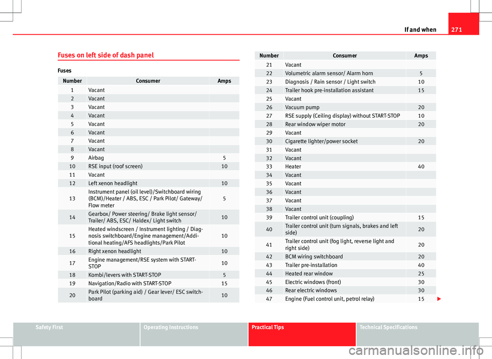
Fuses
Changing a fuse
Blown fuses must be replaced
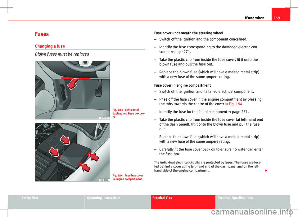
Fig. 183 Left side of
dash panel: Fuse box cov-
er
Fig. 184 Fuse box cover
in engine compartment Fuse cover underneath the steering wheel
–
Switch off the ignition and the component concerned.
– Identify the fuse corresponding to the damaged electric con-
sumer ⇒ page 271.
– Take the plastic clip from inside the fuse cover, fit it onto the
blown fuse and pull the fuse out.
– Replace the blown fuse (which will have a melted metal strip)
with a new fuse of the same ampere rating.
Fuse cover in engine compartment
– Switch off the ignition and its failed electrical component.
– Prise off the fuse cover in the engine compartment by pressing
the tabs towards the centre of the cover ⇒ Fig. 184.
– Identify the fuse for the failed component ⇒ page 271.
– Take the plastic clip from inside the fuse cover (at left-hand end
of the dash panel), fit it onto the blown fuse and pull the fuse
out.
– Replace the blown fuse (which will have a melted metal strip)
with a new fuse of the same ampere rating.
– Carefully fit the fuse cover back on to ensure no water can enter
the fuse box.
The individual electrical circuits are protected by fuses. The fuses are loca-
ted behind a cover at the left-hand end of the dash panel and on the left-
hand side of the engine compartment.
Safety FirstOperating InstructionsPractical TipsTechnical Specifications
Page 273 of 317
271
If and when
Fuses on left side of dash panel
Fuses
NumberConsumerAmps1Vacant 2Vacant 3Vacant 4Vacant 5Vacant 6Vacant 7Vacant 8Vacant 9Airbag510RSE input (roof screen)1011Vacant 12Left xenon headlight10
13Instrument panel (oil level)/Switchboard wiring
(BCM)/Heater / ABS, ESC / Park Pilot/ Gateway/
Flow meter5
14Gearbox/ Power steering/ Brake light sensor/
Trailer/ ABS, ESC/ Haldex/ Light switch10
15Heated windscreen / Instrument lighting / Diag-
nosis switchboard/Engine management/Addi-
tional heating/AFS headlights/Park Pilot10
16Right xenon headlight10
17Engine management/RSE system with START-
STOP10
18Kombi/levers with START-STOP519Navigation/Radio with START-STOP15
20Park Pilot (parking aid) / Gear lever/ ESC switch-
board10
NumberConsumerAmps21Vacant 22Volumetric alarm sensor/ Alarm horn523Diagnosis / Rain sensor / Light switch1024Trailer hook pre-installation assistant1525Vacant 26Vacuum pump2027RSE supply (Ceiling display) without START-STOP1028Rear window wiper motor2029Vacant 30Cigarette lighter/power socket2031Vacant 32Vacant 33Heater4034Vacant 35Vacant 36Vacant 37Vacant 38Vacant 39Trailer control unit (coupling)15
40Trailer control unit (turn signals, brakes and left
side)20
41Trailer control unit (fog light, reverse light and
right side)20
42BCM wiring switchboard2043Trailer pre-installation4044Heated rear window2545Electric windows (front)3046Rear electric windows3047Engine (Fuel control unit, petrol relay)15
Safety FirstOperating InstructionsPractical TipsTechnical Specifications
Page 275 of 317
273
If and when
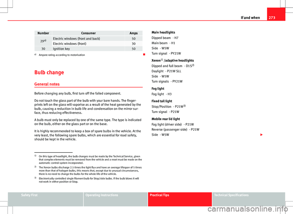
NumberConsumerAmps
29 a)Electric windows (front and back)50Electric windows (front)3030Ignition key50a)
Ampere rating according to motorisation
Bulb change General notes
Before changing any bulb, first turn off the failed component.
Do not touch the glass part of the bulb with your bare hands. The finger-
prints left on the glass will vaporise as a result of the heat generated by the
bulb, causing a reduction in bulb life and condensation on the mirror sur-
face, thus reducing effectiveness.
A bulb must only be replaced by one of the same type. The type is indicated
on the bulb, either on the glass part or on the base.
It is highly recommended to keep a box of spare bulbs in the vehicle. At the
very least, the following spare bulbs, which are essential for road safety,
should be kept in the vehicle. Main headlights
- H7
- H1
- W5W - PY21W
Xenon 1)
/adaptive headlights
- D1S2)
- P21W SLL
- W5W - PY21W
Fog light - H3
Fixed tail light - P21W3)
- P21W
Mobile rear lid light - P21W- P21W
- W5W
Dipped beam
Main beam
Side
Turn signal
Dipped and full beam
Daylight
Side
Turn signals
Fog light
Stop/Position
Turn signal
Fog light (driver side)
Reverse (passenger side)
Side
1)
On this type of headlight, the bulb changes must be made by the Technical Service, given
that complex elements must be removed from the vehicle and a reset must be made on the
automatic control system incorporated.
2) The Xenon bulbs discharge 2.5 times the light flux and have an average lifespan of 5 times
more than that of halogen bulbs, this means that, except due to unusual circumstances,
there is no need to change the bulbs for the whole life of the vehicle.
3) Electronically controlled single filament bulb for Stop/side bulbs. If the bulb blows it will
not work in either position or Stop.
Safety FirstOperating InstructionsPractical TipsTechnical Specifications
Page 277 of 317
275
If and when
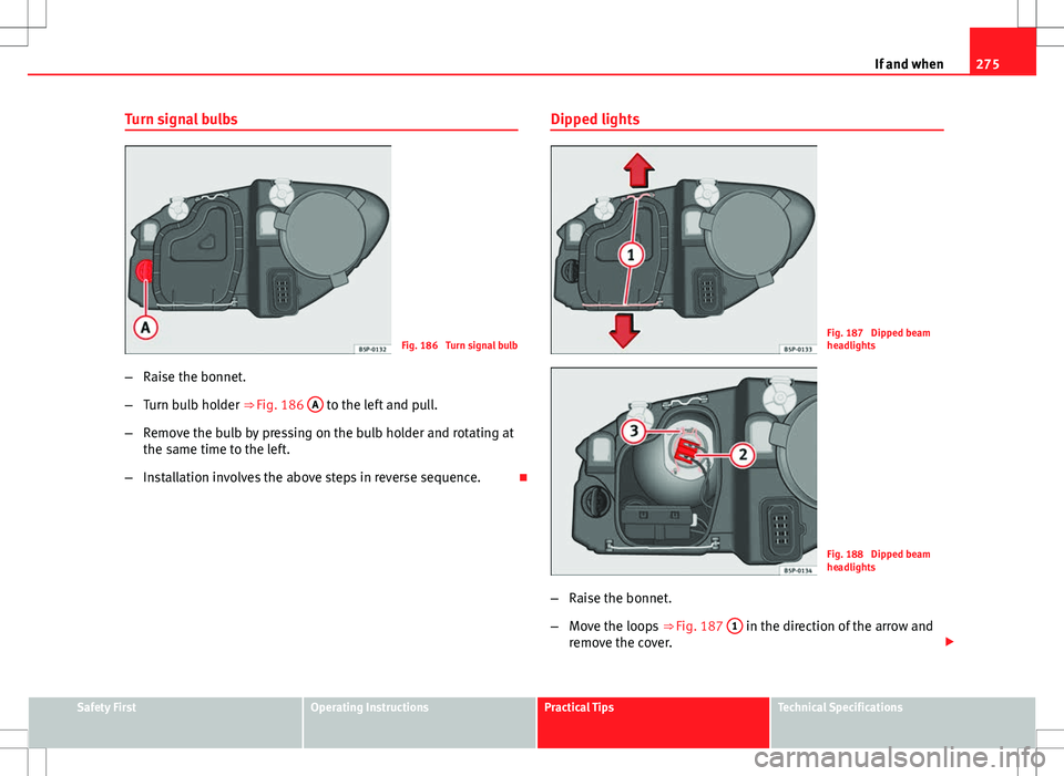
Turn signal bulbs
Fig. 186 Turn signal bulb
– Raise the bonnet.
– Turn bulb holder ⇒ Fig. 186 A
to the left and pull.
– Remove the bulb by pressing on the bulb holder and rotating at
the same time to the left.
– Installation involves the above steps in reverse sequence. Dipped lights
Fig. 187 Dipped beam
headlights
Fig. 188 Dipped beam
headlights
– Raise the bonnet.
– Move the loops ⇒ Fig. 187 1
in the direction of the arrow and
remove the cover.
Safety FirstOperating InstructionsPractical TipsTechnical Specifications