Seat Altea XL 2014 Owner's Manual
Manufacturer: SEAT, Model Year: 2014, Model line: Altea XL, Model: Seat Altea XL 2014Pages: 321, PDF Size: 4.52 MB
Page 261 of 321
259
Wheels and tyres
WARNING
● We recommend that you use only wheels and tyres which have been
approved by SEAT for your model. Failure to do so could impair vehicle
handling. Risk of accident.
● Avoid running the vehicle on tyres that are more than 6 years old. If
you have no alternative, you should drive slowly and with extra care at all
times.
● Never use old tyres or those with an unknown history of use.
● If wheel trims are retrofitted, you must ensure that the flow of air to
the brakes is not restricted. This could cause the brake system to over-
heat.
● All four wheels must be fitted with radial tyres of the same type, size
(rolling circumference) and the same tread pattern.
For the sake of the environment
Old tyres must be disposed of according to the laws in the country con-
cerned.
Note
● For technical reasons, it is not generally possible to use the wheels from
other vehicles. This can also apply to wheels of the same model. The use of
wheels or tyres which have not been approved by SEAT for use with your
model may invalidate the vehicle's type approval for use on public roads.
● If the spare tyre is not the same as the tyres that are mounted on the
vehicle (e.g. winter tyres) you should only use the spare tyre for a short peri-
od of time and drive with extra care. Refit the normal road wheel as soon as
possible. Wheel bolts
Wheel bolts must be tightened to the correct torque.
The design of wheel bolts is matched to the rims. If different wheel rims are
fitted, the correct wheel bolts with the right length and correctly shaped
bolt heads must be used. This ensures that wheels are fitted securely and
that the brake system functions correctly.
In certain circumstances, you should not use wheel bolts from a different
vehicle, even if it is the same model ⇒ page 226.
After the wheels have been changed, the tightening torque of the wheel
bolts should be checked as soon as possible with a torque wrench ⇒
.
The tightening torque for steel and alloy wheels is 120 Nm.
WARNING
If the wheel bolts are not tightened correctly, the wheel could become
loose while driving. Risk of accident.
● The wheel bolts must be clean and turn easily. Never apply grease or
oil to them.
● Use only wheel bolts which belong to the wheel.
● If the tightening torque of the wheel bolts is too low, they could loos-
en whilst the vehicle is in motion. Risk of accident! If the tightening tor-
que is too high, the wheel bolts and threads can be damaged.
CAUTION
The prescribed tightening torque for wheel bolts for steel and alloy wheels
is 120 Nm.
Safety FirstOperating instructionsPractical TipsTechnical Specifications
Page 262 of 321
260Wheels and tyres
Winter tyres
Winter tyres will improve the vehicles handling on snow and
ice.
In winter conditions winter tyres will considerably improve the vehicle's han-
dling. The design of summer tyres (width, rubber compound, tread pattern)
gives less grip on ice and snow.
The winter tyres must be inflated to a pressure 0.2 bar (2.9 psi / 20 kPa)
higher than the pressures specified for summer tyres (see sticker on fuel
tank flap).
Winter tyres must be fitted on all four wheels.
Information on permitted winter tyre sizes can be found in the vehicle's reg-
istration documentation. Use only radial winter tyres. All tyre sizes listed in
the vehicle documentation also apply to winter tyres.
Winter tyres lose their effectiveness when the tread is worn down to a depth
of 4 mm.
The speed rating code ⇒ page 258, New tyres and wheels determines the
following speed limits for winter tyres: ⇒
max. 160 km/h (130 mph)
max. 180 km/h (130 mph)
max. 190 km/h (130 mph)
max. 210 km/h (130 mph)
In some countries, vehicles which can exceed the speed rating of the fitted
tyre must have an appropriate sticker in the driver's field of view. These
stickers are available from your Technical Service. The legal requirements of
each country must be followed.
Do not have winter tyres fitted for unnecessarily long periods. Vehicles with
summer tyres handle better when the roads are free of snow and ice. Q
S
T
H If you have a flat tyre, please refer to the notes on the spare wheel
⇒ page 258, New tyres and wheels.
WARNING
The maximum speed for the winter tyres must not be exceeded. Other-
wise, this could lead to tyre damage and risk of accident.
For the sake of the environment
Fit your summer tyres again as soon as possible. They are quieter, do not
wear so quickly and reduce fuel consumption.
Snow chains
Snow chains are only permitted on front wheels and only for tyres
195/65R15 and 205/55R16. These tyres may only be fitted with fine-pitch
link chains which do not protrude more than 15 mm ⇒ page 296.
Other tyres may use fine-pitch links which do not protrude more than 9 mm,
including tension device.
Remove wheel hub covers and trim rings before fitting snow chains. For
safety reasons cover caps, available in any Technical Service, must then be
fitted over the wheel bolts.
All-wheel drive : Where snow chains are compulsory on certain roads, this
normally also applies to cars with all-wheel drive. Snow chains may only be
fitted to the front wheels (also on vehicles with all-wheel drive).
WARNING
Snow chains should be correctly tightened in accordance with the manu-
facturer's instructions. This will prevent the chains coming into contact
with the wheel housing.
Page 263 of 321
261
Wheels and tyres
CAUTION
Remove the snow chains to drive on roads without snow. Otherwise they
will impair handling, damage the tyres and wear out very quickly.
Note
● In some countries, the maximum permitted speed with snow chains is
50 km/h (31 mph). The legal requirements of each country must be fol-
lowed.
● We recommend that you ask your Technical Service for information
about appropriate wheel, tyre and snow chain size.
Safety FirstOperating instructionsPractical TipsTechnical Specifications
Page 264 of 321
262If and when
If and when
Vehicle tools, tyre repair kit and spare wheel
Vehicle Tools
The vehicle tools are located under the floor panel in the
luggage compartment. – Lift the cover of the luggage compartment, by pulling it up with
a finger in the fitting.
– Take the vehicle tools out of the vehicle.
The vehicle tool kit includes:
● Jack*
● Hook for removing wheel covers* or hub caps*
● Box spanner for wheel bolts*
● Towline anchorage
● Adapter for the anti-theft wheel bolts*
Some of the items listed are only provided in certain model versions, or are
optional extras.
WARNING
● The factory-supplied jack is only designed for changing wheels on
this model. On no account attempt to use it for lifting heavier vehicles or
other loads. Risk of injury.
● Use the jack only on a firm, level ground.
WARNING (Continued)
● Never start the engine when the vehicle is on the jack. Risk of acci-
dent.
● If work is to be carried out underneath the vehicle, this must be se-
cured by suitable stands. Otherwise, there is a risk of injury.
Compact spare wheel* (temporary spare wheel)
The compact spare wheel (temporary spare wheel for vehi-
cles without the anti-puncture kit) should only be used when
strictly necessary.
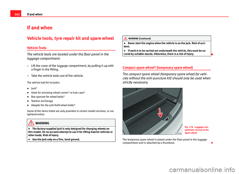
Fig. 178 Luggage com-
partment. Access to the
spare wheel
The temporary spare wheel is stored under the floor panel in the luggage
compartment and is attached by a thumbnut.
Page 265 of 321
263
If and when
How to use the temporary spare wheel
Should you ever have a punctured tyre, the temporary spare wheel is only
intended for temporary use until you can reach a workshop. The standard-
size road wheel should be replaced as soon as possible.
Please note the following restrictions when using the temporary spare
wheel. This temporary spare wheel has been specially designed for your ve-
hicle, thus, it cannot be changed with the temporary spare wheel from an-
other vehicle.
No other type of tyre (normal summer or winter tyre) may be fitted on the
compact temporary spare wheel rim.
Snow chains
For technical reasons, snow chains must not be used on the compact tem-
porary spare wheel.
If you have a puncture on one of the front wheels when using snow chains,
fit the compact temporary spare wheel in place of one of the rear wheels.
You can then attach the snow chains to the wheel taken from the rear and
use this wheel to replace the punctured front wheel.
WARNING
● The tyre pressures must be checked and corrected as soon as possi-
ble after fitting the temporary spare wheel. The temporary spare wheel
pressure for dimensions 125/70R16 125/70R18 135/90R16 is 4.2 bar
(61 psi / 420 kPa); for all other tyre dimensions please refer to the label
on the fuel cap. Failure to do so could result in an accident.
● Do not drive faster than 80 km/h (50 mph), since higher speeds can
cause an accident.
● Avoid heavy acceleration, hard braking and fast cornering. Risk of ac-
cident.
WARNING (Continued)
● Never use more than one temporary spare wheel at the same time,
risk of accident.
● No other type of tyre (normal summer or winter tyre) may be fitted on
the compact temporary spare wheel rim.
Tyre repair kit*
The tyre repair kit (for vehicles not including a temporary
spare wheel) is stored under the floor panel in the luggage
compartment. Your vehicle is equipped with the Tyre Mobility System (tyre repair kit).
The tyre repair kit consists of a container with sealing product to repair the
puncture and a compressor to generate the required tyre pressure. The kit
will reliably seal punctures up to a size of about 4 mm caused by the pene-
tration of a foreign body into the tyre.
Note
● Seek professional assistance if the repair of a tyre puncture is not possi-
ble with the sealing product.
Safety FirstOperating instructionsPractical TipsTechnical Specifications
Page 266 of 321
264If and when
Wheel change
Preparation work
What you must do before changing a wheel.
– If you have a flat tyre or puncture, park the vehicle as far away
from the flow of traffic as possible. Choose a location that is as
level as possible.
– All vehicle occupants should leave the vehicle. They should
wait in a safe area (for instance behind the roadside crash barri-
er).
– Switch off the engine. Switch on the hazard warning lights.
– Apply the handbrake firmly.
– Engage the first gear , or put the selector lever to position P for
those vehicles with an automatic gearbox.
– If you are towing a trailer, unhitch it from your vehicle.
– Take the vehicle tools and the spare wheel out of the luggage
compartment.
WARNING
Put the hazard warning lights on and place the warning triangle in posi-
tion. This is for your own safety and also warns other road users.
CAUTION
If you have to change the tyre on a gradient, block the wheel opposite the
wheel being changed by placing a stone or similar object under it to prevent
the vehicle from rolling away.
Note
Please observe legal requirements when doing so.
Changing a wheel
Change the wheel as described below
– Remove the wheel cover . Also refer to ⇒ Fig. 179
– Slacken the wheel bolts .
– Raise the vehicle with the jack at the corresponding area
– Remove the wheel and put on the spare one
– Lower the vehicle.
– Tighten the wheel bolts firmly with the box spanner
– Replace the hub cap.
After changing a wheel
After changing the wheel there are still tasks to complete. – Put the tools and jack back in the luggage compartment.
Page 267 of 321
265
If and when
– Place the wheel with the defective tyre in the luggage compart-
ment and secure it.
– Check the tyre pressure of the newly fitted tyre as soon as pos-
sible.
– Have the tightening torque of the wheel bolts checked as soon
as possible with a torque wrench. The prescribed torque must
be 120 Nm.
Note
● If you notice that the wheel bolts are corroded and difficult to turn when
changing a wheel, they must be replaced before having the wheel bolt tight-
ening torque checked.
● For safety reasons, drive at moderate speeds until the wheel bolt tight-
ening torque has been checked. Wheel trims
The wheel trims must be removed to gain access to the
wheel bolts.
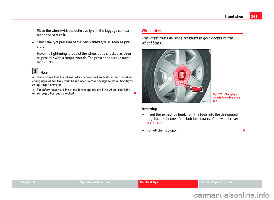
Fig. 179 Changing a
wheel: Removing a hub
cap
Removing
– Insert the extraction hook from the tools into the designated
ring, located in one of the bolt hole covers of the wheel cover
⇒ Fig. 179.
– Pull off the hub cap.
Safety FirstOperating instructionsPractical TipsTechnical Specifications
Page 268 of 321
266If and when
Wheel covers*
The wheel covers must be removed for access to the wheel
bolts
Removing
– Remove the wheel cover using the wire hook.
– Hook this into one of the cut-outs of the wheel cover.
Fitting
– Fit the wheel cover onto the wheel rim by pressing it firmly. Put
pressure initially on the point of the cut-out for the valve. Then
press the wheel cover onto the steel rim so that it engages all
round. Loosening the wheel boltsThe wheel bolts must be loosened before raising the vehicle.
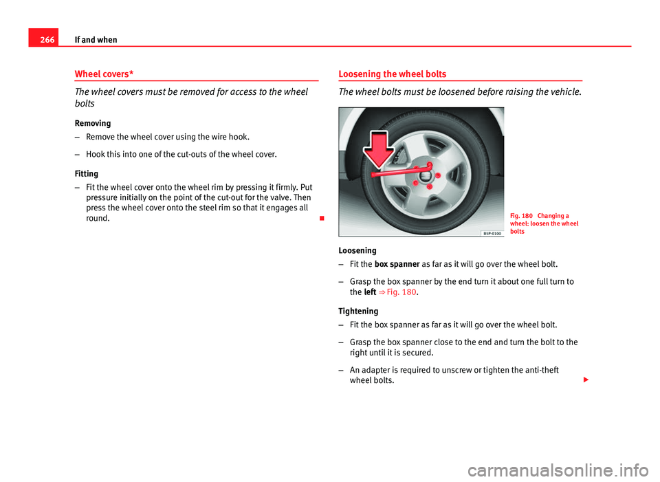
Fig. 180 Changing a
wheel: loosen the wheel
bolts
Loosening
– Fit the box spanner as far as it will go over the wheel bolt.
– Grasp the box spanner by the end turn it about one full turn to
the left ⇒ Fig. 180.
Tightening
– Fit the box spanner as far as it will go over the wheel bolt.
– Grasp the box spanner close to the end and turn the bolt to the
right until it is secured.
– An adapter is required to unscrew or tighten the anti-theft
wheel bolts.
Page 269 of 321

267
If and when
WARNING
Loosen the wheel bolts only about one turn before raising the vehicle
with the jack, loosening the wheel bolts more than one turn can result in
an accident.
Note
● If the wheel bolt is very tight, you may be able to loosen it by pushing
down the end of the spanner carefully with your foot. Hold on to the vehicle
for support and take care not to slip.
Raising the vehicle
In order to remove the wheel, the vehicle must be raised
with a jack.
Fig. 181 Jack position
points
Fig. 182 Fitting the jack
– Locate the jacking point under the door sill closest to the wheel
to be changed ⇒ Fig. 181.
– Place the jack under the jacking point and turn the crank until
the arm of the jack is directly below the vertical rib under the
door sill.
– Align the jack so that the arm of the jack fits around the rib un-
der the door sill and the movable base plate of the jack is flat
on the ground ⇒ Fig. 182.
– Raise the jack until the defective wheel is just clear of the
ground.
Recesses at the front and rear of the door sills mark the jacking points
⇒ Fig. 181. There is only one jacking point for each wheel. Do not fit the jack
anywhere else.
An unstable surface under the jack may cause the vehicle to slip off the
jack. Therefore, the jack must be fitted on solid ground offering good sup-
port. Use a large and stable base, if necessary. On a hard, slippery surface
(such as tiles) use a rubber mat or similar to prevent the jack from slipping.
Safety FirstOperating instructionsPractical TipsTechnical Specifications
Page 270 of 321

268If and when
WARNING
● Take all precautions so that the base of the jack does not slip. Failure
to do so could result in an accident.
● The vehicle can be damaged if the jack is not applied at the correct
jacking points. There is also a risk of injury since the jack can slip off
suddenly if it is not properly engaged.
Jack position points for vehicles with sill panel trim *
Fig. 183 Plastic sill pan-
el trim with jack allot-
ment cover
Vehicles with plastic sill panel trim, with cover*
– Remove the cap A
to access the anchor point for the vehicle
jack ⇒
Fig. 183.
– Pull on the cover and remove it from its allotment in the direc-
tion of the arrow ⇒
Fig. 183. –
Once the cover has been released, it will remain connected to
its strap so that is not lost.
Removing and fitting the wheel
For removal and fitting the wheel, the following tasks must
be completed.
Change the wheel as described below after loosening the wheel
bolts and raising the vehicle with the jack.
Removing a wheel
– Unscrew the wheel bolts using the box spanner and place them
on a clean surface.
Fitting a wheel
– Screw on the wheel bolts in position and tighten them loosely
with a box spanner.
The wheel bolts should be clean and easily screwed. Before fitting the spare
wheel, inspect the wheel condition and hub mounting surfaces. These sur-
faces must be clean before fitting the wheel.
If tyres with a specific direction of rotation are fitted, note the direction of
rotation.