display Seat Arona 2017 Owner's Guide
[x] Cancel search | Manufacturer: SEAT, Model Year: 2017, Model line: Arona, Model: Seat Arona 2017Pages: 308, PDF Size: 6.66 MB
Page 117 of 308
Instruments and warning/control lamps
Speed warning
When the s peed settin
g i
s exceeded, this will
be indicated on the instrument panel display.
This is very useful, for example when using
winter tyres that are not designed for driving
at the maximum speed of the vehicle
››› page 40.
The speed warning settings can be adjusted
in the Easy Connect system via the button
and the S
ET
TINGS function button
› ›
›
page 118.
Start-Stop operating display
Updated information relating to the status is
displayed on the instrument panel
››› page 196.
Identifying letters on engine (MKB)
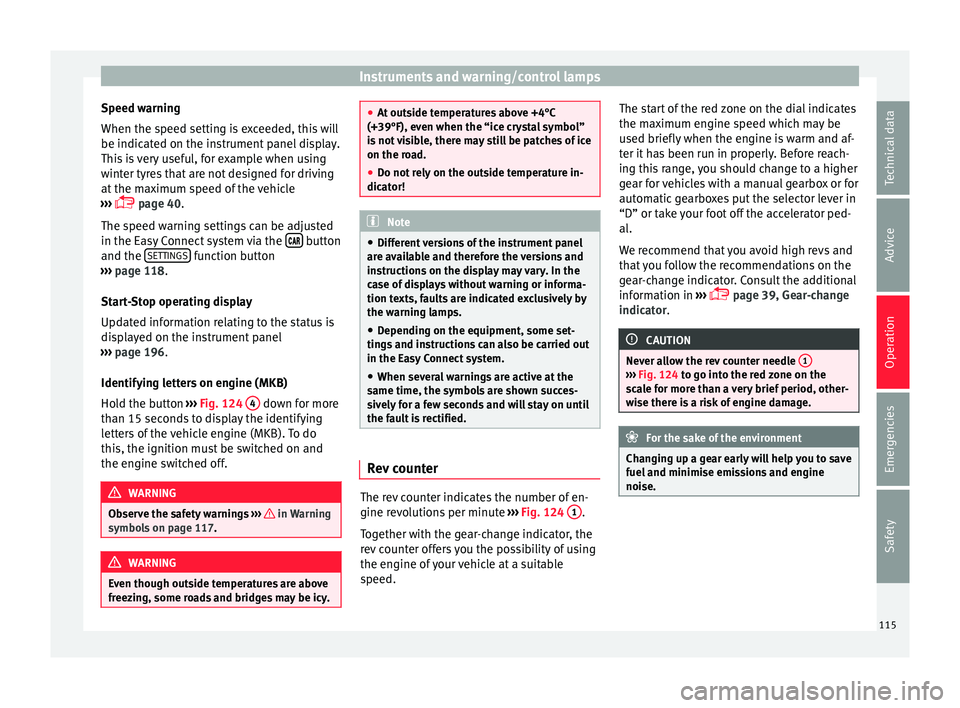
Hold the button ››› Fig. 124 4 down for more
th an 15 sec
ond
s to display the identifying
letters of the vehicle engine (MKB). To do
this, the ignition must be switched on and
the engine switched off. WARNING
Observe the safety warnings ›››
in Warning
symbol s on p
age 117. WARNING
Even though outside temperatures are above
freez in
g, some roads and bridges may be icy. ●
At out s
ide temperatures above +4°C
(+39°F), even when the “ice crystal symbol”
is not visible, there may still be patches of ice
on the road.
● Do not rely on the outside temperature in-
dicator! Note
● Diff erent
versions of the instrument panel
are available and therefore the versions and
instructions on the display may vary. In the
case of displays without warning or informa-
tion texts, faults are indicated exclusively by
the warning lamps.
● Depending on the equipment, some set-
tings
and instructions can also be carried out
in the Easy Connect system.
● When several warnings are active at the
same time, the symbol
s are shown succes-
sively for a few seconds and will stay on until
the fault is rectified. Rev counter
The rev counter indicates the number of en-
gine r
ev
o
lutions per minute ››› Fig. 124 1 .
T og
ether w
ith the gear-change indicator, the
rev counter offers you the possibility of using
the engine of your vehicle at a suitable
speed. The start of the red zone on the dial indicates
the maximum en
gine speed which may be
used briefly when the engine is warm and af-
ter it has been run in properly. Before reach-
ing this range, you should change to a higher
gear for vehicles with a manual gearbox or for
automatic gearboxes put the selector lever in
“D” or take your foot off the accelerator ped-
al.
We recommend that you avoid high revs and
that you follow the recommendations on the
gear-change indicator. Consult the additional
information in ›››
page 39, Gear-change
indicator. CAUTION
Never allow the rev counter needle 1 ›››
Fig. 124 to g o int
o the red zone on the
scale for more than a very brief period, other-
wise there is a risk of engine damage. For the sake of the environment
Changing up a gear early will help you to save
fuel and minimi
se emissions and engine
noise. 115
Technical data
Advice
Operation
Emergencies
Safety
Page 118 of 308
Operation
Odometer Fig. 125
Instrument panel: odometer and re-
set b
utt
on. The distance covered is displayed in “kilome-
tr
e
s” or mi
les “m”. It is possible to change
the measurement units (kilometres
“km”/miles “m”) in the radio/Easy Connect*.
Please refer to the Easy Connect* Instructions
Manual for more details.
Odometer/trip recorder
The odometer shows the total distance cov-
ered by the vehicle.
The trip recorder shows the distance that has
been travelled since it was last reset. It is
used to measure short trips. The last digit of
the trip recorder indicates distances of 100
metres or tenths of a mile.
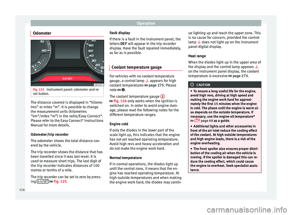
The trip recorder can be set to zero by press-
ing 0.0/SET
› ›
› Fig. 125
. Fault display
If there i
s a fault in the instrument panel, the
letters DEF will appear in the trip recorder
display. Have the fault repaired immediately,
as far as is possible.
Coolant temperature gauge For vehicles with no coolant temperature
gaug
e, a c
ontrol lamp appears for high
coolant temperatures ››› page 273. Please
note ››› .
The c oo
l
ant temperature gauge 2 ›››
Fig. 124 only w
orks when the ignition is
switched on. In order to avoid engine dam-
age, please read the following notes for the
different temperature ranges.
Engine cold
If only the diodes in the lower part of the
scale light up, this indicates that the engine
has not yet reached operating temperature.
Avoid high revs and heavy acceleration and
do not make the engine work hard.
Normal temperature
If in normal operations, the diodes light up
until the central zone, it means that the en-
gine has reached operating temperature. At
high outside temperatures and when making
the engine work hard, the diodes may contin- ue lighting up and reach the upper zone. This
is
no c
ause for concern, provided the control
lamp does not light up on the instrument
panel digital display.
Heat range
When the diodes light up in the upper area of
the display and the control lamp appears
on the instrument panel display, the coolant
temperature is excessive ››› page 273. CAUTION
● To en s
ure a long useful life for the engine,
avoid high revs, driving at high speed and
making the engine work hard for approxi-
mately the first 15 minutes when the engine
is cold. The phase until the engine is warm al-
so depends on the outside temperature. If
necessary, use the engine oil temperature*
››› page 40 as a guide.
● Additional lights and other accessories in
front of
the air inlet reduce the cooling effect
of the coolant. At high outside temperatures
and high engine loads, there is a risk of the
engine overheating.
● The front spoiler also ensures proper distri-
bution of the c
ooling air when the vehicle is
moving. If the spoiler is damaged this can re-
duce the cooling effect, which could cause
the engine to overheat. Seek specialist assis-
tance. 116
Page 119 of 308
Instruments and warning/control lamps
Fuel level Fig. 126
Fuel gauge. The display
6
› ›
› Fig. 124 only works when
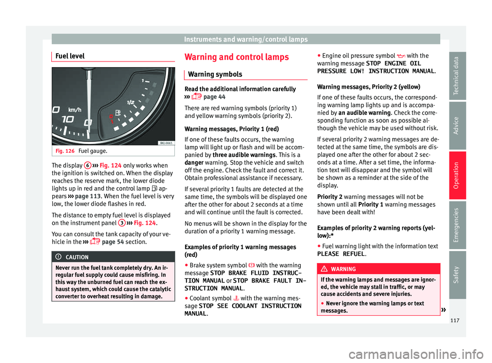
the ignition is switched on. When the display
reaches the reserve mark, the lower diode
lights up in red and the control lamp ap-
pears ››› page 113. When the fuel level is very
low, the lower diode flashes in red.
The distance to empty fuel level is displayed
on the instrument panel 3
› ›
› Fig. 124
.
You can consult the tank capacity of your ve-
hicle in the ›››
page 54 section. CAUTION
Never run the fuel tank completely dry. An ir-
re gu
lar fuel supply could cause misfiring. In
this way the unburned fuel can reach the ex-
haust system, which could cause the catalytic
converter to overheat resulting in damage. Warning and control lamps
W arnin
g symbo
ls Read the additional information carefully
›› ›
page 44
There are red warning symbols (priority 1)
and yellow warning symbols (priority 2).
Warning messages, Priority 1 (red)
If one of these faults occurs, the warning
lamp will light up or flash and will be accom-
panied by three audible warnings. This is a
danger warning. Stop the vehicle and switch
off the engine. Check the fault and correct it.
Obtain professional assistance if necessary.
If several priority 1 faults are detected at the
same time, the symbols will be displayed one
after the other for about 2 seconds at a time
and will continue until the fault is corrected.
No menus will be shown in the display for the
duration of a priority 1 warning message.
Examples of priority 1 warning messages
(red)
● Brake system symbol with the warnin
g
message STOP BRAKE FLUID INSTRUC-
TION MANUAL or STOP BRAKE FAULT IN-
STRUCTION MANUAL .
● Coolant symbol with the warnin
g mes-
sage STOP SEE COOLANT INSTRUCTION
MANUAL . ●
Engine oil
pressure symbol with the
warning message STOP ENGINE OIL PRESSURE LOW! INSTRUCTION MANUAL .
Warning messages, Priority 2 (yellow)
If one of these faults occurs, the correspond-
ing warning lamp lights up and is accompa-
nied by an audible warning. Check the corre-
sponding function as soon as possible al-
though the vehicle may be used without risk.
If several priority 2 warning messages are de-
tected at the same time, the symbols are dis-
played one after the other for about 2 sec-
onds at a time. After a set time, the informa-
tion text will disappear and the symbol will
be shown as a reminder at the side of the
display.
Priority 2 warning messages will not be
shown until all Priority 1 warning messages
have been dealt with!
Examples of priority 2 warning reports (yel-
low):*
● Fuel warning light with the information text
PLEASE REFUEL . WARNING
If the warning lamps and messages are ignor-
ed, the v ehic
le may stall in traffic, or may
cause accidents and severe injuries.
● Never ignore the warning lamps or text
mess
ages. » 117
Technical data
Advice
Operation
Emergencies
Safety
Page 120 of 308
Operation
●
Stop the v
ehicle safely as soon as possible.
● Park the vehicle away from traffic and en-
sure th
at there are no highly flammable ma-
terials under the vehicle that could come into
contact with the exhaust system (e.g. dry
grass, fuel).
● A faulty vehicle represents a risk of acci-
dent for the driv
er and for other road users. If
necessary, switch on the hazard warning
lamps and put out the warning triangle to ad-
vise other drivers.
● Before opening the bonnet, switch off the
engine and al
low it to cool.
● In any vehicle, the engine compartment is a
hazar
dous area and could cause severe inju-
ries ››› page 267. CAUTION
Failure to heed the control lamps and text
mes s
ages when they appear may result in
faults in the vehicle. Introduction to the Easy
C
onnect
sy
stem*
System settings (CAR)* CAR menu Read the additional information carefully
›› ›
page 33
To select the settings menus, depending on
the version, press the Easy Connect button and the
S
ET
TINGS function button, OR
pr e
s
s the button and then SETTINGS .
The act ual
number of
menus available and
the name of the various options in these me-
nus will depend on the vehicle’s electronics
and equipment.
Pressing the menu button will always take
you to the last menu used.
When the function button check box is activa-
ted , the function is active.
Pressing the menu button will always take
y ou t
o the l
ast menu used.
Any changes made using the settings menus
are automatically saved on closing those me-
nus.
Function buttons in the vehicle settings
menuPage
ESC system››› page 177
Tyres››› page 282
Driver assistance››› table on page 33
Parking and manoeuvring››› page 236
Vehicle lights››› table on page 33
Mirrors and windscreen wipers››› table on page 33
Opening and closing››› table on page 33
Multifunction display››› table on page 33
Date and time››› table on page 33
Units››› table on page 33
Service››› page 114
Factory settings››› table on page 33 WARNING
Any distraction may lead to an accident, with
the risk of
injury. Operating the Easy Connect
system while driving could distract you from
traffic. 118
Page 129 of 308
Opening and closing
Note
For anti-theft security, only the driver door is
fitted w ith a loc
k cylinder.“Safe” security system*
This is an anti-theft device which consists of
a doubl
e loc
k for the door locks and a deacti-
vation function for the boot in order to pre-
vent forced entry.
Activation
The “safe” system is activated when the vehi-
cle is locked using the key or the remote con-
trol.
To activate it with the key, rotate once it is in-
serted in the door lock cylinder in the locking
direction.
To activate the system using the remote con-
trol, press the lock button once on the re-
mote.
Once this system is activated, opening doors
from the outside and the inside is not possi-
ble. The rear lid can not be opened. The cen-
tral lock button does not work.
When the ignition is switched off, the instru-
ment panel display indicates that the “Safe”
system is on. Deactivation
Rot
at
e the key inserted in the lock cylinder
twice towards the locking direction.
To activate the system using the remote con-
trol, press the lock button on the remote
twice in less than five seconds.
On deactivating the “Safe” system, the alarm
volumetric sensor is also deactivated.
With the “Safe” switched off, doors can be
opened from the interior but not from the ex-
terior.
See “Selective unlocking system*”
“Safe” status
On the driver door, there is warning lamp visi-
ble from outside the vehicle through the win-
dow which shows the “Safe” system status.
We will know that “Safe” system is activated
by the flashing warning lamp. The indicator
will flash on all vehicles, fitted and nor fitted
with an alarm, until they unlock.
Remember:
Safe activated with or without an alarm:
warning lamp flashes continuously.
Safe deactivated without an alarm: the warn-
ing lamp stays off.
Safe deactivated with an alarm: the warning
lamp stays off. WARNING
No one should remain inside the vehicle if the
“Safe” sy s
tem is activated because opening
the doors will not be possible in the event of
an emergency neither from the inside nor the
outside and help from the outside is made
difficult. Danger of death. Passengers could
become trapped inside in case of emergency. Selective unlocking system*
This system allows to unlock either just the
driv
er door or al
l
the vehicle.
Driver door unlock button
Unlock once. Use either the key or the remote
control.
Once the key is inserted in the lock cylinder,
rotate once in the unlock direction. The driver
door will remain without “Safe” and un-
locked. In vehicles fitted with an alarm, see
the Anti-theft Alarm section ›››
page 132.
Using the remote control, press the unlock
button on the remote once. The “Safe” sys-
tem for all the vehicle is deactivated, only the
driver door is unlocked and both the alarm
and the warning lamp are also turned off. »
127
Technical data
Advice
Operation
Emergencies
Safety
Page 133 of 308
Opening and closing
blocked for engine ignition ››
› page 168. In
order to enable engine ignition, the button
on the key inside the vehicle needs to be
pr e
s
sed.
Automatically disabling sensors
If the vehicle is not locked or unlocked for a
long period of time, the proximity sensors on
the passenger doors are automatically disa-
bled.
If one of the sensor surfaces on the door han-
dles is often activated in an unusual manner
with the vehicle locked (e.g. by the branches
of a bush rubbing against it), all proximity
sensors are disabled for a certain period of
time.
Sensors will again be enabled: ● After a time.
● OR: if the vehicle is unlocked with the but-
ton on the key.
● OR: if the rear lid is open.
● OR: if
the vehicle is unlocked manually with
the key
.
Keyless Access temporary disconnection
function
There is a sequence of actions to be followed
if you wish to temporarily deactivate Keyless
Access. First of all, lock the vehicle with the
key. As of this moment, you have 5 seconds to perform the second locking action through
the door handle sen
sor.
If this second action is performed more than
5 seconds after the vehicle is locked with the
key, it will not be possible to deactivate Key-
less Access.
Once Keyless Access has been temporarily
deactivated, the vehicle can only be unlocked
using the key. The Keyless Access function
will be reactivated once it has been unlocked.
Convenience functions
To close all the electric windows using the
convenience function, keep a finger on the
locking sensor surface ››› Fig. 141 B (arrow)
of the door h
andl
e for a few seconds until the
windows have closed.
The doors opened by touching the sensor
surface of the door handle depend on the
settings that have been activated in the Easy
Connect system with the button and the
S ET
TINGS and
Openin
g and c
lo
sing function but-
t on
s. CAUTION
The sensor surfaces on the door handles
cou l
d engage if hit with a water jet or high
pressure steam if there is a valid vehicle key
in the proximity. If at least one of the electric
windows is open and the sensor surface B (arrow) on the handle is activated continu-
ous
ly
, all windows will close. Note
● If the v
ehicle battery has little or no charge,
or the vehicle key battery is almost or entire-
ly out of charge, you will probably not be able
to lock or unlock the vehicle with the Keyless
Access system. The vehicle can be unlocked
or locked manually.
● To control the proper locking of the vehicle,
the rele
ase function is disabled for approx. 2
seconds.
● If the message Keyless access system
faulty is di
splayed on the screen of the
dash panel, abnormalities may occur in the
operation of the Keyless Access system. Con-
tact a specialised workshop. SEAT recom-
mends visiting a SEAT dealership for this.
● Depending on the function set on the info-
tainment sy
stem for the mirrors, the exterior
mirrors will unfold and the surround lighting
will come on when unlocking the vehicle us-
ing the sensor surface on the driver door han-
dle.
● If there is no valid key inside the vehicle or
the syst
em fails to detect one, a warning will
display on the dash panel screen. This could
happen if any other radio frequency signal in-
terferes with the key signal (e.g. from a mo-
bile device accessory) or if the key is covered
by another object (e.g. an aluminium case).
● If the sensors are very dirty, e.g. have a lay-
er of sa
lt, the correct functioning of the sen-
sors on the door handles may be affected. In
this case, clean the vehicle. » 131
Technical data
Advice
Operation
Emergencies
Safety
Page 140 of 308
Operation
Switching lights on and off Read the additional information carefully
›› ›
page 30
The driver is personally responsible for the
correct use and adjustment of the lights in all
situations. Note
● The le g
al requirements regarding the use of
vehicle lights in each country must be ob-
served.
● The dipped beam headlights will only work
with the ignition on. The s
ide lights come on
automatically when the ignition is turned off.
● If the lights are left on after the key has
been taken out
of the ignition lock, an audi-
ble warning sounds while the driver door re-
mains open. This is a reminder to switch the
lights off.
● The rear fog light can dazzle drivers behind
you. Y
ou should use the rear fog light only
when visibility is very poor. For this reason, if
you exceed approximately 60 km/h (38 mph),
the instrument panel will display the follow-
ing warming: Switch off the fog light!
● The use of the lighting described here is
subj
ect to the relevant statutory require-
ments. Automatic lighting*
Activation
– Rotate the switch to the po
sition, this
indication will light up.
Deactivation
– Turn the light switch to .
Automatic
lighting
If automatic headlight control is switched on,
dipped beam headlights are automatically
switched on by a photosensor if you drive in-
to a tunnel, for example. WARNING
● Ev en if
the automatic headlight control is
switched on, the dipped beam headlights will
not be switched on with fog. Therefore, the
dipped beam must be switched on manually. Note
● For v
ehicles with the automatic headlight
system, when the key is removed from the ig-
nition, the audible warning will only sound if
the light knob is in position .
● The use of the lighting described here is
subj
ect to the relevant statutory require-
ments. ●
Do not p ut
stickers on the windscreen in
front of the sensor. This may cause disrup-
tions or faults in the automatic lighting sys-
tem.
● The rain sensor switches on the dipped
beam hea
dlights when the windscreen wipers
have been operating continuously for a few
seconds and it switches the lights off when
the continuous or interval wipe is switched
off for some minutes. Daytime running lights
The daytime running lights consist of individ-
ual
lights, int
e
grated in the front headlights.
By connecting the daytime running lights,
these lights are switched on 1)
››› .
The d a
ytime ru
nning lights switch on every
time the ignition is switched on, if the switch
is in positions or , according to the level
of exterior lighting.
When the light switch is in position , a
light sensor automatically switches dipped
beam on and off (including the control and
instrument lighting) or the daytime running
lights depending on the level of exterior
lighting. 1)
On vehicles equipped with rear LED lights, the rear
side light i
s switched on as well.
138
Page 144 of 308
Operation
All turn signals flash simultaneously when
the h az
ar
d warning lights are switched on.
The two turn signal turn signal lamps
and the turn signal lamp in the switch will
flash at the same time. The simultaneous
hazard warning lights also work when the ig-
nition is switched off. WARNING
● The risk of
an accident increases if your ve-
hicle breaks down. Always use the hazard
warning lights and a warning triangle to draw
the attention of other road users to your sta-
tionary vehicle.
● Due to the high temperatures that the cata-
lytic con
verter can reach, never park in an
area where the catalytic converter could come
into contact with highly inflammable materi-
als, for example dry grass or spilt petrol. This
could start a fire. Note
● The batt er
y will run down if the hazard
warning lights are left on for a long time,
even if the ignition is switched off.
● The use of the hazard warning lights de-
scribed her
e is subject to the relevant statu-
tory requirements. Interior lights
R el
at
ed video Fig. 147
Convenience Lighting of instruments and controls
The lighting level of instruments, controls
and di
s
p
lays can be adjusted through the
Easy Connect system using the button
and the S
ET
TINGS function button
› ›
›
page 33.
The instrument lighting (some dials and nee-
dles), the centre console lighting and the
lighting of the displays are regulated by a
photodiode incorporated in the instrument
panel.
The instrument lighting (needles) is switched
on when the ignition is on and the light is
off. The instrument lighting is dimmed auto-
matically as the daylight starts to fade. It
goes out completely when ambient light is
very low. This function is intended to remind
the driver to switch on the dipped beam headlights in good time when light condi-
tions bec
ome poor.
Interior and reading lights Read the additional information carefully
›› ›
page 32
Luggage compartment lighting
The light is activated when the rear lid is
open, even when the ignition and lights are
turned off. For this reason, ensure that the
rear lid is always closed.
Ambient light*
The ambient light lights up the area of the
centre console and the footwell area and, de-
pending on the version, the front door panels
as well.
It will be switched on at full brightness when
the doors are opened and the lights will be
dimmed during driving, when the light selec-
tor is in the , or position.
The brightness of the ambient light* can be
adjusted through the Easy Connect menu, as
can colour, in versions with lighting on the
front door panel (see Adjusting Lights >
Interior lighting ›››
page 33).
142
Page 168 of 308
Operation
● Adju s
t
the vents so that the air flow is di-
rected slightly upwards.
Change between degrees Centigrade and de-
grees Fahrenheit
Keep the and buttons held down for 2
seconds at the same time. The data is dis-
played on the screen in the units required.
Automatic mode
Automatic mode is used to maintain a con-
stant temperature and demist the windows
inside the vehicle.
● Set the interior temperature between +16°C
(+64°F) and +29°C (+84°F).
● Adjus
t the vents so that the air flow is di-
rected s
lightly upwards.
● Press the butt
on, AUTO is displayed on
the screen.
Automatic mode is switched off by pressing
the air distribution buttons or increasing or
decreasing the blower speed. However, the
temperature remains regulated.
Adjusting the temperature
● When you switch on the ignition, control 1›››
Fig. 172 can be u sed t
o set the required in-
terior temperature.
It is possible to select interior temperatures
from +16°C (+64°F) to +29°C (+84°F). In this range the temperature is regulated automati-
cal
ly
. If a temperature below +16°C (+64°F) is
selected, “LO” is displayed on the screen. If a
temperature above +29°C (+84°F) is selected,
“HI” is displayed on the screen. At both ex-
tremes, Climatronic works at maximum cool-
ing or heating power, respectively. The tem-
perature is not regulated.
In the event of prolonged, irregular distribu-
tion of the air flow from the outlets (particu-
larly the footwells) and significant differen-
ces in temperature, e.g. on leaving the vehi-
cle, sensitive people may catch cold.
Fan regulation
Climatronic automatically regulates blower
speed according to the interior temperature.
It is possible, however, to set the blower
speed to suit requirements.
● Press the 2 buttons to increase or reduce
f an s
peed.
C
limatronic will switch off when the blower
switches off.
Turn on windscreen defrost
● Press the button ›››
Fig. 172.
Switching off windscreen defrosting
● Press the button sev
eral times or
press the button. The temperature is regulated automatically.
The air output fr
om the vents ››› Fig. 169 2 is increased.
WARNING
Read and observe the safety warnings ›››
in
Genera l
notes on page 158. Note
● A v i
sit to the specialised service once a
year is recommended to clean the Climatronic
system.
● The interior temperature sensor is at the
bottom. Do not c
over it with stickers or the
like, as this could have a negative effect on
Climatronic operations. 166
Page 169 of 308
Driving
Driving Ad dr
e
ss
Introduction The power steering is not hydraulic but elec-
tromec
h
anical. The advantage of this steer-
ing is that it foes not need flexible hydraulic
pipes, hydraulic oil, pump, filter or other
parts. The electromechanical system saves
fuel. Whereas a hydraulic system needs con-
tinuous oil pressure, electromechanical
steering only needs power when it is used.
In vehicles with electromechanical steering,
the assisted steering function automatically
adjusts according to vehicle speed, steering
wheel torque and wheel orientation. The
power steering only works when the engine
is running. WARNING
If the power steering does not work, you will
need much mor e s
trength to turn the wheel.
This has a considerable effect on vehicle
safety.
● The power steering only works when the
engine is
running.
● Never allow the vehicle to move when the
engine is
switched off.
● Never remove the key from the ignition
while the
vehicle is moving. The steering lock could be engaged and vehicle steering would
not w
ork. Note
The ignition of the vehicle being towed must
be sw itc
hed on to prevent the steering wheel
from locking and also to allow the use of the
turn signals, horn, windscreen wipers and
washers. Control lamp
The control lamp should light up for a few
sec
ond
s
when the ignition is switched on. It
should go out once the engine is started.
It lights up red
The electromechani-
cal steering is dam-
aged.Have the steering checked im-
mediately by a specialised work-
shop.
It lights up yellow
Electromechanical
steering operation
is limited.See a specialised workshop im-
mediately and have the steering
checked.
If the yellow warning lamp does
not light up again after the en-
gine is restarted and the vehicle
has travelled a short distance,
you do not need to take it to a
specialised workshop.
It lights up yellow
The 12-volt battery
was disconnected
and has been recon-
nected.Take the vehicle for a short run
at 15-20 km/h (9-12 mph).
It flashes yellow
The steering column
is tight.Turn the wheel a little to both
sides.
The steering column
does not unlock or
lock.Remove the key from the ignition
and switch the ignition back on.
If necessary, check the messag-
es displayed on the instrument
panel display.
Do not drive on if
the steering
column remains locked after the
ignition has been switched on.
Seek specialist assistance. WARNING
If the warning lamps and the corresponding
mes s
ages are ignored when they light up, the
vehicle may stall in traffic and cause acci-
dents and severe injuries.
● Never ignore the warning lamps or messag-
es.
● Stop the
vehicle at the next opportunity
and in a safe p
lace. » 167
Technical data
Advice
Operation
Emergencies
Safety