handbrake Seat Arona 2017 Owner's Manual
[x] Cancel search | Manufacturer: SEAT, Model Year: 2017, Model line: Arona, Model: Seat Arona 2017Pages: 308, PDF Size: 6.66 MB
Page 50 of 308
The essentials
››› in Selector lever positions on
page 184
››› page 183
››› page 48 Manual release of the selector lever
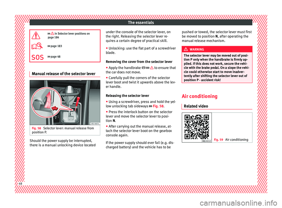
Fig. 58
Selector lever: manual release from
po s
ition P
. Should the power supply be interrupted,
ther
e i
s
a manual unlocking device located under the console of the selector lever, on
the right. Rel
easing the selector lever re-
quires a certain degree of practical skill.
● Unlocking: use the flat part of a screwdriver
bla
de.
Removing the cover from the selector lever
● Apply the handbrake ›››
to ensure that
the c ar doe
s
not move.
● Carefully pull the corners of the selector
lever boot
and twist it upwards above the lev-
er handle.
Releasing the selector lever
● Using a screwdriver, press and hold the yel-
low un
locking tab sideways ››› Fig. 58.
● Press the interlock button on the selector
lever and mo
ve the selector lever to posi-
tion N.
● After carrying out the manual release, at-
tach the sel
ector lever boot on the gearbox
console again.
If the power supply should ever fail (e.g. dis-
charged battery) and the vehicle has to be pushed or towed, the selector lever must first
be moved t
o position N, after operating the
manual release mechanism. WARNING
The selector lever may be moved out of posi-
tion P only when the h
andbrake is firmly ap-
plied. If this does not work, secure the vehi-
cle with the brake pedal. On a slope the vehi-
cle could otherwise start to move inadver-
tently after shifting the selector lever out of
position P - accident risk! Air conditioning
R el
at
ed video Fig. 59
Air conditioning48
Page 62 of 308
The essentials
Action in the event of a punc-
t ur
e
R
elated video Fig. 72
Wheels What to do first
●
Park the vehicle on a horizontal surface
and in a s af
e p
lace as far away from traffic as
possible.
● Apply the handbrake.
● Switch on the hazard warning lights.
● Manual gearbox: select the 1s
t gear.
● Automatic gearbox: Move the sel
ector lever
to position P.
● If you are towing a trailer, unhitch it from
your v
ehicle.
● Have the vehicle tool kit* ›››
page 61 and
the spare wheel ›››
page 283 ready.
● Observe the applicable legislation for each
countr
y (reflective vest, warning triangles,
etc.). ●
All
occupants should leave the vehicle and
wait in a safe place (for instance behind the
roadside crash barrier). WARNING
● Alw a
ys observe the above steps and pro-
tect yourself and other road users.
● If you change the wheel on a slope, block
the wheel on the oppo
site side of the car with
a stone or similar to prevent the vehicle from
moving. Repairing a tyre with the anti-punc-
t
ur
e k
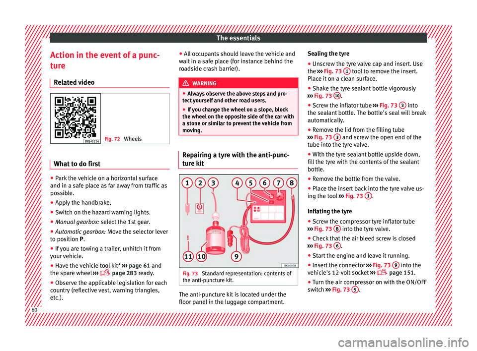
it Fig. 73
Standard representation: contents of
the anti-p u
nct
ure kit. The anti-puncture kit is located under the
floor p
anel
in the lug
gage compartment. Sealing the tyre
● Unscrew the tyre valve cap and insert. Use
the ›››
Fig. 73 1 tool to remove the insert.
Pl ac
e it
on a clean surface.
● Shake the tyre sealant bottle vigorously
›››
Fig. 73 10 .
● Screw the inflator tube ››
›
Fig. 73 3 into
the se al
ant
bottle. The bottle's seal will break
automatically.
● Remove the lid from the filling tube
›››
Fig. 73 3 and screw the open end of the
t ube int
o the ty
re valve.
● With the tyre sealant bottle upside down,
fill
the tyre with the contents of the sealant
bottle.
● Remove the bottle from the valve.
● Place the insert back into the tyre valve us-
ing the too
l ››› Fig. 73 1 .
Infl atin
g the ty
re
● Screw the compressor tyre inflator tube
›››
Fig. 73 8 into the tyre valve.
● Check that the air bleed screw is closed
› ›
›
Fig. 73 6 .
● Start the engine and leave it running.
● Insert the connector ››
›
Fig. 73 9 into the
v ehic
l
e's 12-volt socket ›››
page 151.
● Turn the air compressor on with the ON/OFF
swit c
h ››› Fig. 73 5 .
60
Page 113 of 308
Controls and displays
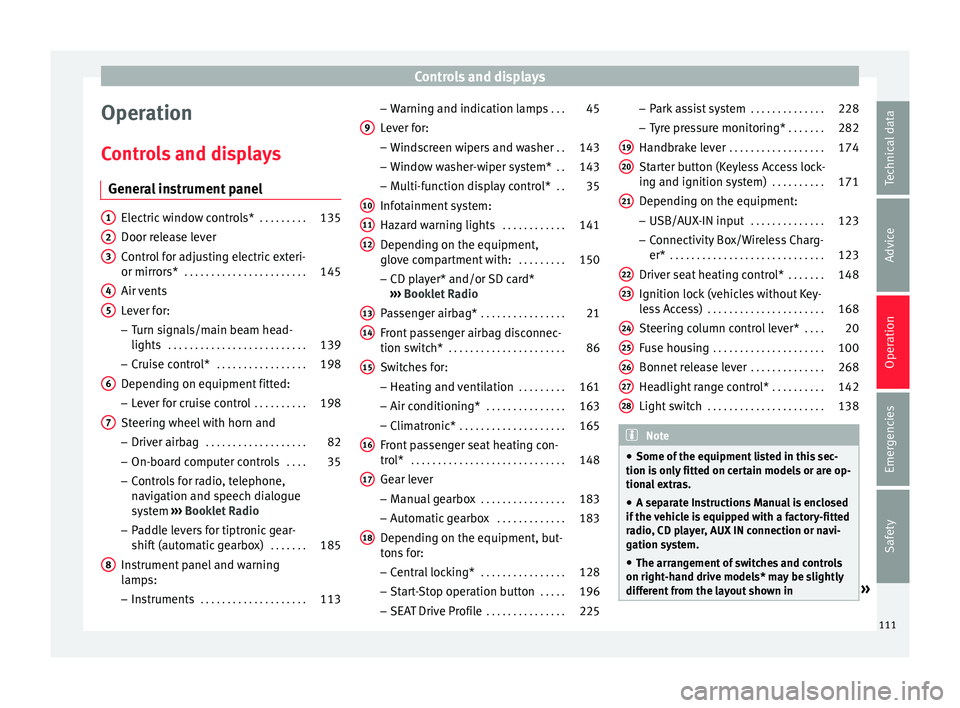
Operation
C ontr
o
ls and displays
General instrument panel Electric window controls*
. . . . . . . . .135
Door release lever
Contr o
l for adjusting electric exteri-
or mirrors* . . . . . . . . . . . . . . . . . . . . . . . 145
Air vents
Lev er f
or:
– Turn signals/main beam head-
lights . . . . . . . . . . . . . . . . . . . . . . . . . . 139
– Crui se c
ontrol* . . . . . . . . . . . . . . . . . 198
Depending on equipment fitted:
– Lev er f
or cruise control . . . . . . . . . .198
Steering wheel with horn and – Driver airbag . . . . . . . . . . . . . . . . . . . 82
– On-boar d c
omputer controls . . . .35
– Contro
ls for radio, telephone,
navigation and speech dialogue
system ›››
Booklet Radio
– Paddle levers for tiptronic gear-
shift (automatic gearbox) . . . . . . .185
Instrument panel and warning
lamp s:
– In
struments . . . . . . . . . . . . . . . . . . . . 113
1 2
3
4
5
6
7
8 –
Warnin
g and indic
ation lamps . . .45
Lever for:
– Winds
creen wipers and washer . .143
– Window w
asher-wiper system* . .143
– Multi-f
unction display control* . .35
Infotainment system:
Hazard w
arning lights . . . . . . . . . . . . 141
Depending on the equipment,
glove c
ompartment with: . . . . . . . . .150
– CD pla
yer* and/or SD card*
››› Booklet Radio
Passenger airbag* . . . . . . . . . . . . . . . . 21
Front passenger airbag disconnec-
tion switc
h* . . . . . . . . . . . . . . . . . . . . . . 86
Switches for:
– Heating and
ventilation . . . . . . . . . 161
– Air conditionin g* . . . . . . . . . . . . . . . 163
– C
limatr
onic* . . . . . . . . . . . . . . . . . . . . 165
Front passenger seat heating con-
tro l* . . . . . . . . . . . . . . . . . . . . . . . . . . . . . 148
Ge
ar lever
– Manual g
earbox . . . . . . . . . . . . . . . . 183
– Autom atic
gearbox . . . . . . . . . . . . . 183
Depending on the equipment, but-
ton s
for:
– Central locking* . . . . . . . . . . . . . . . . 128
– Star t
-Stop operation button . . . . .196
– SEAT Driv
e Profile . . . . . . . . . . . . . . . 225
9
10
11
12
13
14
15
16
17
18 –
Park
a
ssist system . . . . . . . . . . . . . . 228
– Tyr
e pressure monitoring* . . . . . . .282
Handbrake lever . . . . . . . . . . . . . . . . . . 174
Starter button (Keyless Access lock-
ing and ignition sys
tem) . . . . . . . . . . 171
Depending on the equipment:
– USB/AUX-IN inp
ut . . . . . . . . . . . . . . 123
– Connectivity
Box/Wireless Charg-
er* . . . . . . . . . . . . . . . . . . . . . . . . . . . . . 123
Driver seat heating control* . . . . . . .148
Ignition lock (vehicles without Key-
les
s Access) . . . . . . . . . . . . . . . . . . . . . . 168
Steering column control lever* . . . .20
Fuse housing . . . . . . . . . . . . . . . . . . . . . 100
Bonnet release lever . . . . . . . . . . . . . .268
Headlight range control* . . . . . . . . . .142
Light switch . . . . . . . . . . . . . . . . . . . . . . 138 Note
● Some of the equipment li
sted in this sec-
tion is only fitted on certain models or are op-
tional extras.
● A separate Instructions Manual is enclosed
if the v
ehicle is equipped with a factory-fitted
radio, CD player, AUX IN connection or navi-
gation system.
● The arrangement of switches and controls
on right-hand driv
e models* may be slightly
different from the layout shown in » 19
20
21
22
23
24
25
26
27
28
111
Technical data
Advice
Operation
Emergencies
Safety
Page 143 of 308
Lights and visibility
Motorway light* The motorway light is available on vehicles
equipped w
ith f
ull-LED lights.
The function is connected/disconnected via
the corresponding Easy Connect system
menu.
● Activation: when going abo
ve 110 km/h
(68 mph) for more than 10 seconds, the dip-
ped beam raises slightly to increase the driv-
er's visibility distance.
● Deactivation: when reduc in
g the speed of
the car below 100 km/h (62 mph), the dip-
ped beam returns to its normal position.
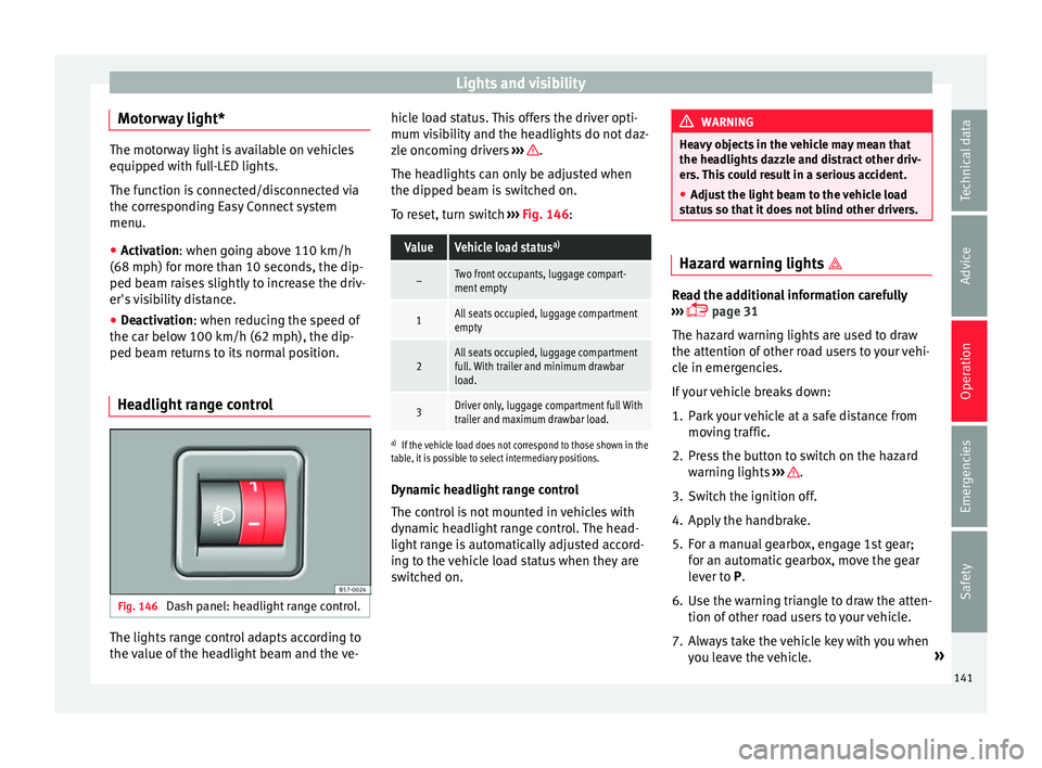
Headlight range control Fig. 146
Dash panel: headlight range control. The lights range control adapts according to
the
v
alue of
the headlight beam and the ve- hicle load status. This offers the driver opti-
mum vi
sibility and the headlights do not daz-
zle oncoming drivers ››› .
The he a
dlights
can only be adjusted when
the dipped beam is switched on.
To reset, turn switch ››› Fig. 146:
ValueVehicle load status a)
–Two front occupants, luggage compart-
ment empty
1All seats occupied, luggage compartment
empty
2All seats occupied, luggage compartment
full. With trailer and minimum drawbar
load.
3Driver only, luggage compartment full With
trailer and maximum drawbar load.
a)
If the vehicle load does not correspond to those shown in the
table, it is possible to select intermediary positions.
Dynamic headlight range control
The control is not mounted in vehicles with
dynamic headlight range control. The head-
light range is automatically adjusted accord-
ing to the vehicle load status when they are
switched on. WARNING
Heavy objects in the vehicle may mean that
the hea dlight
s dazzle and distract other driv-
ers. This could result in a serious accident.
● Adjust the light beam to the vehicle load
stat
us so that it does not blind other drivers. Hazard warning lights
Read the additional information carefully
›› ›
page 31
The hazard warning lights are used to draw
the attention of other road users to your vehi-
cle in emergencies.
If your vehicle breaks down:
1. Park your vehicle at a safe distance from mov in
g traffic.
2. Press the button to switch on the hazard warning lights
››› .
3. Switch the ignition off.
4. Apply the handbrake.
5. For a manual gearbox, engage 1st gear; for an aut
om
atic gearbox, move the gear
lever to P.
6. Use the warning triangle to draw the atten- tion of other ro
ad users to your vehicle.
7. Always take the vehicle key with you when you le
ave the vehicle. »
141
Technical data
Advice
Operation
Emergencies
Safety
Page 176 of 308
Operation
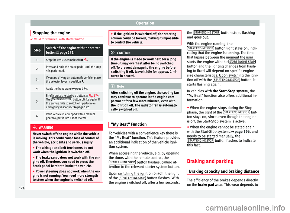
Stopping the engine 3 Valid for vehicles: with starter buttonStepSwitch off the engine with the starter
button
››› page 171.
1.Stop the vehicle completely ››› .
2.Press and hold the brake pedal until the step
4 is performed.
3.If you are driving an automatic vehicle, place
the selector lever in position P.
4.Apply the handbrake ››› page 174.
5.
Briefly press the start-up button ››› Fig. 174.
The START ENGINE STOP button blinks again. If
the engine fails to switch off, perform an
emergency disconnect ››› page 172.
6.If the vehicle is equipped with a manual
gearbox, put it into 1st or reverse. WARNING
Never switch off the engine while the vehicle
is mo
ving. This could cause loss of control of
the vehicle, accidents and serious injury.
● The airbags and belt tensioners do not
work when the ignition i
s switched off.
● The brake servo does not work with the en-
gine off. Ther
efore, you need to press the
break pedal harder to brake the vehicle.
● Power steering does not work when the en-
gine is not
running. You need more strength
to steer when the engine is switched off. ●
If the ignition i s
switched off, the steering
column could be locked, making it impossible
to control the vehicle. CAUTION
If the engine is made to work hard for a long
time, it ma
y overheat after being switched
off. To prevent damage to the engine before
switching it off, leave it idle for approx. 2 mi-
nutes in neutral. Note
After switching off the engine, the cooling fan
ma y
continue to operate in the engine com-
partment for a few more minutes, even with
the ignition off. The radiator fan is automati-
cally switched off. “My Beat” Function
For vehicles with a convenience key there is
the “M
y
B
eat” function. This feature provides
an additional indication of the vehicle igni-
tion system.
When accessing the vehicle, e.g. by opening
the doors with the remote control, the START ENGINE STOP button flashes, calling at-
t ention t
o the r
elevant starter system button.
Upon switching the ignition on/off, the light
of the START ENGINE STOP button flashes. With
the en gine sw
it
ched off, after a few seconds, the
STOP ENGINE
START button stops flashing
and g oe
s
out.
With the engine running, the START ENGINE STOP button light stays on, indi-
c atin
g th
at the engine is running. The time
that lapses between the moment the user
starts the engine with the START ENGINE STOP button and the lighting changes from flash-
in
g t
o fi
xed will depend on specific engine
size characteristics. Upon switching the igni-
tion off with the START ENGINE STOP button, it
s t
ar
ts flashing again.
In vehicles with the Start-Stop system , the
“My Beat” function also offers additional in-
formation:
● When the engine stops during the Stop
phase, the light
of the START ENGINE STOP but-
t on s
t
ays on, since, even though the engine
is off, the Start-Stop system is active.
● When the engine cannot be stated again
with the St
art-Stop system, ››› page 196, and
needs to be started manually, the START ENGINE STOP button flashes to indicate
thi s
f
act.
Braking and parking Brakin
g capacity and braking distance The efficiency of the brakes depends directly
on the br
ak
e p
ad wear. This wear depends to
174
Page 177 of 308
Driving
a great extent on the conditions under which
the v
ehic
le is operated and the way the vehi-
cle is driven. If you often drive in town, drive
short distances or have a sporty driving style,
we recommend that you have the thickness
of your brake pads checked by technical serv-
ices more frequently than recommended in
the Maintenance Programme.
If you drive with wet brakes, for example, af-
ter crossing areas of water, on days of heavy
rainfall or even after washing the car, the ef-
fect of the brakes is reduced as the brake
discs are wet or even frozen (in winter): in
this case, the brakes should be “dried” by
pressing the brake pedal several times. WARNING
Longer braking distances and faults in the
brak e sy
stem increase the risk of accidents.
● New brake pads must be run in and do not
have the c
orrect friction during the first
200 km. This reduced braking capacity may
be compensated for by pressing on the brake
pedal a little harder, which also applies when
the brake pads have to be changed further
on.
● If brakes are wet or frozen, or if you are
driving on r
oads which have been salted,
braking power may be lower than normal.
● On steep slopes, if brakes are excessively
used, they w
ill overheat. Before driving down
a long steep slope, it is advisable to reduce
speed and change down into a lower gear or range (depending on the type of transmis-
sion).
Thu
s, make use of engine braking and
relieve the brakes.
● Never let the brakes “drag” by applying
light pre
ssure. Continuous braking will cause
the brakes to overheat and the braking dis-
tance will increase. Apply and then release
the brakes alternately.
● Never let the vehicle run with the engine
switc
hed off. The braking distance is in-
creased considerably when the brake servo is
not active.
● If the brake fluid loses its viscosity and is
subj
ected to heavy use, vapour bubbles can
form in the brake system. This reduces the ef-
ficiency of the brakes.
● Non-standard or damaged front spoilers
coul
d restrict the airflow to the brakes and
cause them to overheat. Before purchasing
accessories please observe the relevant in-
structions ››› page 255, Modifications.
● If a brake system circuit fails, the braking
dist
ance will be increased considerably. Con-
tact a specialised workshop immediately and
avoid unnecessary journeys. Control lamp
Situations in which the warning lamp lights
up *
●
the brake fluid level is too low
› ›
›
page 275. ●
there is
a fault in the brake system.
This warning lamp can light up together with
the ABS system warning lamp. WARNING
● If the br ak
e warning lamp does not go out
or if it lights up when driving, the brake fluid
level in the reservoir is too low so there is a
risk of an accident ››› page 275, Brake fluid.
Stop the vehicle and do not drive on. Obtain
technical assistance.
● If the brake warning lamp lights up to-
gether w
ith the ABS lamp this could be
due to an ABS fault. This could cause the rear
wheels to lock quickly when you brake. This
could cause the rear to break away. Risk of
skidding. Stop the vehicle and seek technical
assistance. Handbrake
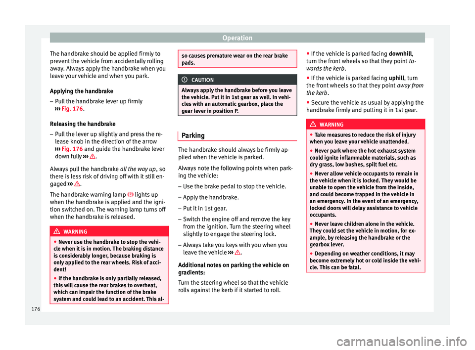
Fig. 176
Handbrake between the front seats. » 175
Technical data
Advice
Operation
Emergencies
Safety
Page 178 of 308
Operation
The handbrake should be applied firmly to
pr ev
ent
the vehicle from accidentally rolling
away. Always apply the handbrake when you
leave your vehicle and when you park.
Applying the handbrake
– Pull the handbrake lever up firmly
›››
Fig. 176.
Releasing the handbrake
– Pull the lever up slightly and press the re-
lea
se knob in the direction of the arrow
››› Fig. 176 and guide the handbrake lever
down fully ››› .
A lw
a
ys pull the handbrake all the way up, so
there is less risk of driving off with it still en-
gaged ››› .
The h andbr
ak
e warning lamp lights up
when the handbrake is applied and the igni-
tion switched on. The warning lamp turns off
when the handbrake is released. WARNING
● Never u se the h
andbrake to stop the vehi-
cle when it is in motion. The braking distance
is considerably longer, because braking is
only applied to the rear wheels. Risk of acci-
dent!
● If the handbrake is only partially released,
this w
ill cause the rear brakes to overheat,
which can impair the function of the brake
system and could lead to an accident. This al- so causes premature wear on the rear brake
pa
d
s. CAUTION
Always apply the handbrake before you leave
the vehic
le. Put it in 1st gear as well. In vehi-
cles with an automatic gearbox, place the
gear lever in position P. Parking
The handbrake should always be firmly ap-
p
lied when the
v
ehicle is parked.
Always note the following points when park-
ing the vehicle: – Use the brake pedal to stop the vehicle.
– Apply the handbrake.
– Put it in 1st gear.
– Switch the engine off and remove the key
from the ignition. T
urn the steering wheel
slightly to engage the steering lock.
– Always take you keys with you when you
leav
e the vehicle ››› .
Ad dition
a
l notes on parking the vehicle on
gradients:
Turn the steering wheel so that the vehicle
rolls against the kerb if it started to roll. ●
If the v
ehicle is parked facing downhill,
turn the front wheels so that they point to-
wards the kerb .
● If the vehicle is parked facing uphill
, turn
the front wheels so that they point away from
the kerb.
● Secure the vehicle as usual by applying the
handbrak
e firmly and putting it in 1st gear. WARNING
● Tak e me
asures to reduce the risk of injury
when you leave your vehicle unattended.
● Never park where the hot exhaust system
coul
d ignite inflammable materials, such as
dry grass, low bushes, spilt fuel etc.
● Never allow vehicle occupants to remain in
the vehic
le when it is locked. They would be
unable to open the vehicle from the inside,
and could become trapped in the vehicle in
an emergency. In the event of an emergency,
locked doors will delay assistance to vehicle
occupants.
● Never leave children alone in the vehicle.
They cou
ld set the vehicle in motion, for ex-
ample, by releasing the handbrake or the
gearbox lever.
● Depending on weather conditions, it may
become extr
emely hot or cold inside the vehi-
cle. This can be fatal. 176
Page 184 of 308
Operation
Via the ESC, the XDS will brake the inside
wheel and c
ou
nter the excess driving torque
of that wheel. This means that the driver's
desired trajectory is much more precise.
The XDS system works in combination with
the ESC and is always active, even when ASR
traction control is disconnected or the ESC is
in Sport mode.
Brake servo The brake servo increases the pressure you
ap
p
ly
to the brake pedal. It works only when
the engine is running .
If the brake servo is not functioning, e.g. due
to a malfunction, or if the vehicle is being
towed, you will have to press the brake pedal
considerably harder to make up for the lack
of servo assistance. WARNING
The braking distance can also be affected by
ext ern
al factors.
● Never let the vehicle coast with the engine
switc
hed off. Failure to follow this instruction
could result in an accident. The braking dis-
tance is increased considerably when the
brake servo is not active.
● If the brake servo is not working, for exam-
ple when the
vehicle is being towed, you will
have to press the brake pedal considerably
harder than normal. Hill driving assistant*
Fig. 177
Related video This function is only included in vehicles with
ESC.
The hi l
l driving assistant helps the driver to
move off and upward on a hill when the vehi-
cle is stationary.
The system maintains brake pressure for ap-
proximately two seconds after the driver
takes his foot off the brake pedal to prevent
the vehicle from lurching backward when it is
started. During these 2 seconds, the driver
has enough time to release the clutch pedal
and accelerate without the vehicle moving
and without having to use the handbrake,
making start-up easier, more comfortable
and safer.
These are the basic operation conditions:
● being on a ramp or hill/slope,
● doors closed,
● vehicle completely stationary,
● engine running and foot on the brake, ●
bes ide
s having a gear engaged or being in
neutral for manual gear change and with the
selector lever at position S, D or R for an au-
tomatic gearbox.
This system is also active when reversing up-
hill. WARNING
● If y
ou do not start the vehicle immediately
after taking your foot off the brake pedal, the
vehicle may start to roll back under certain
conditions. Depress the brake pedal or use
the hand brake immediately.
● If the engine stalls, depress the brake ped-
al or u
se the hand brake immediately.
● When following a line of traffic uphill, if you
want t
o prevent the vehicle from rolling back
accidentally when starting off, hold the brake
pedal down for a few seconds before starting
off. Note
The Official Service or a specialist workshop
can t el
l you if your vehicle is equipped with
this system. 182
Page 186 of 308
Operation
N – Neutral (idling)
W ith the sel
ect
or lever in this position, the
gear is in neutral.
D/S – Permanent drive (forward) position
The selector lever in the D/S position enables
the gears to be controlled in normal mode (D)
or Sport (S). To select Sport mode (S), move
the selector lever backwards. Moving the lev-
er again will select normal mode (D). The se-
lected driving mode is shown on the instru-
ment panel display.
In normal mode (D), the gearbox automatical-
ly selects the best gear ratio. This depends
on the engine load, the road speed and the
dynamic gear control programme (DCP).
Sport mode (S) must be selected for a sporty
driving style. This setting makes use of the
engine's maximum power output. When ac-
celerating the gear shifts will be noticeable.
Press the brake pedal to move the selector
lever from N to D/S when the vehicle is sta-
tionary or at speeds below 3 km/h (2 mph)
››› .
Under c er
t
ain circumstances (e.g. when driv-
ing in mountains) it can be advantageous to
switch temporarily to tiptronic mode
››› page 185, in order to manually select gear
ratios to suit the driving conditions. WARNING
● Tak e c
are not to accidentally press the ac-
celerator pedal when the vehicle is stopped.
The vehicle could otherwise start moving im-
mediately (in some cases even if the parking
brake is engaged) resulting in the risk of an
accident.
● Never move the selector lever to R or P
when driving. F
ailure to follow this instruc-
tion could result in an accident.
● With selector lever in any position (except
P) the vehic
le must always be held with the
foot brake when the engine is running. This is
because an automatic gearbox still transmits
power even at idling speed, and the vehicle
tends to “creep”. The accelerator pedal must
on no account be pressed inadvertently when
a gear is engaged with the vehicle stationary.
The vehicle could otherwise start moving im-
mediately (in some cases even if the parking
brake is engaged) resulting in the risk of an
accident.
● While you are selecting a gear and the vehi-
cle i
s stopped with the engine running, do
not accelerate. Failure to follow this instruc-
tion could result in an accident.
● As a driver you should never leave your ve-
hicle if
the engine is running and a gear is en-
gaged. If you have to leave your vehicle while
the engine is running, you must apply the
handbrake and engage the parking lock (P).
● To avoid accidents, apply the handbrake
and put the sel
ector lever in position P before
opening the bonnet and working on the vehi- cle with the engine running. Please always
ob
ser
ve the important safety warnings
››› page 267, Working in the engine compart-
ment. Note
● If the sel ect
or lever is moved accidentally
to N when driving, release the accelerator and
let the engine speed drop to idling before se-
lecting gear range D or S again.
● Should the power supply to the selector
lever be int
errupted in position P, the selector
lever will be locked. If this should happen the
manual release can be used ›››
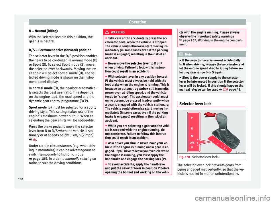
page 48. Selector lever lock
Fig. 178
Selector lever lock. The selector lever lock prevents gears from
bein g en
g
aged inadvertently, so that the ve-
hicle is not set in motion unintentionally.
184
Page 188 of 308
Operation
The tiptronic gives the driver the option to
c h
an
ge gears manually.
Changing gear manually with the selector
lever
It is possible to change to tiptronic mode,
both when the vehicle is stopped and while
driving.
– To switch to tiptronic mode, move the se-
lector l
ever from position D/S to the right.
As soon as the change is made the selector
level will be shown in the position M on the
instrument panel display (for example M4
means that the fourth gear is engaged).
– Move the selector lever forwards + to se-
l ect
a higher g
ear ››› Fig. 179.
– Move the selector lever backwards – to
sel ect
a lo
wer gear.
Changing gear manually with the gearshift
paddles*
The gearshift paddles can be used when the
selector lever is in the position D/S or M.
– Press the gearshift paddle + to select a
higher g e
ar ›
›› Fig. 180.
– Press the gearshift paddle – to select a
lo w
er g
ear.
– With the selector lever in position D/S, if no
pad
dle is operated during a short period of
time, the gearbox control system switches
back to automatic mode. To switch to per- manent manual gear change using the
gear
shift paddles, move the selector lever
from position D/S to the right.
When accelerating, the gearbox automatical-
ly shifts up into the next gear shortly before
the maximum engine speed is reached.
If you select a lower gear, the automatic gear-
box will not shift down until there is no risk of
over-revving the engine.
When the kick-down feature is used, the
gearbox shifts down to a lower gear, depend-
ing on road speed and engine speed.
Driving tips The gearbox changes gear ratios automatical-
ly
a
s
the vehicle moves.
The engine can only start with the selector
lever in position P or N. At low temperatures,
below -10°C (50°F), the engine can only start
with the selector lever in position P.
Starting the vehicle
– Press and hold the brake pedal.
– Press and hold the interlock button (the
button on the sel
ector lever handle), move
the selector lever to the desired position,
for instance D ›››
page 183, and release the
interlock button. –
Wait f
or the gearbox to engage the gear (a
slight movement can be felt).
– Release the brake and press the accelerator
›››
.
St op
pin
g briefly
– Apply the foot brake to hold the vehicle
briefly when st
ationary (for instance at traf-
fic lights). Do not press the accelerator.
Stopping/Parking
If the driver door is opened and the selector
lever is not in position P, the vehicle could
move. The driver message will be: Gear
change: selector lever in the
drive position! . Additionally, a buzzer
will sound.
– Press and hold the brake pedal ›››
.
– Apply the handbrake.
– Move the selector lever to position P.
Ho l
din
g the car on a hill
– Always apply the brake pedal firmly to pre-
vent
the vehicle from “moving backwards;
if necessary, apply the handbrake” ››› .
Do not tr y
t
o stop the vehicle “rolling back”
by increasing the engine speed when a
gear is engaged (pressing the accelerator)
››› .
186