key Seat Ateca 2016 Workshop Manual
[x] Cancel search | Manufacturer: SEAT, Model Year: 2016, Model line: Ateca, Model: Seat Ateca 2016Pages: 328, PDF Size: 6.32 MB
Page 190 of 328
Operation
●
Do not s
top in the water, drive in reverse, or
stop the engine in any situation.
● Note that vehicles travelling in the opposite
direction m
ay splash water that could exceed
the maximum permitted water height for your
vehicle.
● Avoid driving through salt water (corro-
sion). Driver assistance systems
St ar
t-Stop System*
Description and operation The Start-Stop system helps save fuel and re-
duc
e C
O2 emissions.
In Start-Stop mode, the engine will automati-
cally switch off when the vehicle stops, when
stopping at traffic lights for example. The ig-
nition remains switched on during the stop-
ping phase. The engine automatically
switches back on when required. In this sit-
uation the light of the START ENGINE STOP but-
t on s
tays on.
As soon as the ignition is switched on, the
Start-Stop function is automatically activa-
ted.
Basic requirements for the Start-Stop mode
● The driver door must be closed.
● The driver must have their seat belt fas-
tened.
● The bonnet
must be closed.
● The engine must have reached a minimum
serv
ice temperature.
● The reverse gear must not be engaged.
● The vehicle must not be on a very steep
slope. WARNING
● Nev er sw
itch the engine off until the vehi-
cle is stationary. The brake servo and power
steering functions will not be completely cov-
ered under warranty. More force may also be
needed to turn the steering wheel or to brake.
As you cannot steer and brake in the normal
manner, there is a greater risk of accidents
and serious injury.
● Never remove the key from the ignition if
the v
ehicle is in motion. Otherwise, the steer-
ing could lock making it impossible to steer
the vehicle.
● To avoid injury, make sure that the Start-
Stop sy
stem is switched off when working in
the engine compartment ››› page 190. CAUTION
The Start-Stop system must always be
sw it
ched off when driving through flooded
areas ››› page 190. Stopping/Starting the engine
Vehicles with a manual gearbox
– When the vehicle is stopped, put it into
neutr al
and release the clutch pedal. The
engine will switch off. The warning lamp
will appear on the instrument panel dis-
play.
188
Page 226 of 328
Operation
● in the c a
se of special constructions to the
side of the vehicle, e.g., high or irregular di-
viders.
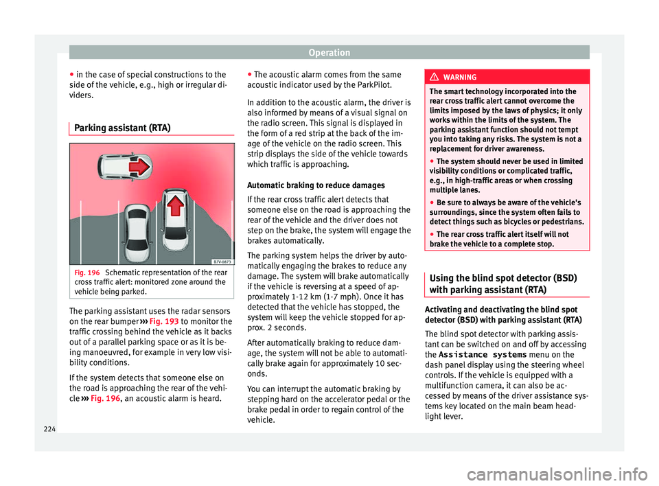
Parking assistant (RTA) Fig. 196
Schematic representation of the rear
c r
oss traffic alert: monitored zone around the
vehicle being parked. The parking assistant uses the radar sensors
on the r
e
ar bumper ››› Fig. 193 to monitor the
traffic crossing behind the vehicle as it backs
out of a parallel parking space or as it is be-
ing manoeuvred, for example in very low visi-
bility conditions.
If the system detects that someone else on
the road is approaching the rear of the vehi-
cle ››› Fig. 196, an acoustic alarm is heard. ●
The acou
stic alarm comes from the same
acoustic indicator used by the ParkPilot.
In addition to the acoustic alarm, the driver is
also informed by means of a visual signal on
the radio screen. This signal is displayed in
the form of a red strip at the back of the im-
age of the vehicle on the radio screen. This
strip displays the side of the vehicle towards
which traffic is approaching.
Automatic braking to reduce damages
If the rear cross traffic alert detects that
someone else on the road is approaching the
rear of the vehicle and the driver does not
step on the brake, the system will engage the
brakes automatically.
The parking system helps the driver by auto-
matically engaging the brakes to reduce any
damage. The system will brake automatically
if the vehicle is reversing at a speed of ap-
proximately 1-12 km (1-7 mph). Once it has
detected that the vehicle has stopped, the
system will keep the vehicle stopped for ap-
prox. 2 seconds.
After automatically braking to reduce dam-
age, the system will not be able to automati-
cally brake again for approximately 10 sec-
onds.
You can interrupt the automatic braking by
stepping hard on the accelerator pedal or the
brake pedal in order to regain control of the
vehicle. WARNING
The smart technology incorporated into the
r e
ar cross traffic alert cannot overcome the
limits imposed by the laws of physics; it only
works within the limits of the system. The
parking assistant function should not tempt
you into taking any risks. The system is not a
replacement for driver awareness.
● The system should never be used in limited
vi
sibility conditions or complicated traffic,
e.g., in high-traffic areas or when crossing
multiple lanes.
● Be sure to always be aware of the vehicle's
surr
oundings, since the system often fails to
detect things such as bicycles or pedestrians.
● The rear cross traffic alert itself will not
brak
e the vehicle to a complete stop. Using the blind spot detector (BSD)
w
ith p
arking assistant (RTA) Activating and deactivating the blind spot
det
ect
or (BSD) with parking assistant (RTA)
The blind spot detector with parking assis-
tant can be switched on and off by accessing
the Assistance systems menu on the
dash panel display using the steering wheel
controls. If the vehicle is equipped with a
multifunction camera, it can also be ac-
cessed by means of the driver assistance sys-
tems key located on the main beam head-
light lever.
224
Page 229 of 328
Driver assistance systemsDriving
profileCharacteristics
Offroad a)It adjusts the vehicle's parameters in or-
der to maintain optimal off-road driving.
Snowa)It adjusts the vehicle's behaviour for driv-
ing on slippery road surfaces, optimising
grip and manoeuvrability.
a)
Only for 4Drive models. WARNING
When operating SEAT Drive Profile, pay atten-
tion t o a
ll traffic: doing otherwise could cause
an accident. Note
● When the v
ehicle is switched off it will al-
ways store the driving profile that was selec-
ted when the ignition key was removed, ex-
cept in the following cases:
– When the vehicle is restarted after using
the Sport profile, the engine and the
gearbox will not restart in the sportiest
setting so as to reduce fuel consumption.
To return the engine and the gearbox to
their sportiest position, select the Sport
driving profile again.
– When the vehicle is restarted after using
the Offroad or Snow settings, the sys-
tem is always activated in the Normal
profile. ●
Your s
peed and driving style must always
be adjusted to visibility, weather, and traffic
conditions.
● The Eco profile is not recommended when
t
owing a vehicle. Kick-down
The Kick-down feature allows maximum ac-
c
el
eration to be reached.
If the Eco* profile has been selected in the
SEAT Drive Profile ››› page 226 and the
accelerator is pressed beyond a hard point,
the engine power is automatically controlled
to give your vehicle maximum acceleration. WARNING
Please note that if the road surface is slip-
per y
or wet, the kick-down feature could
cause the driving wheels to spin, which could
result in skidding. 227
Technical data
Advice
Operation
Emergencies
Safety
Page 238 of 328
Operation
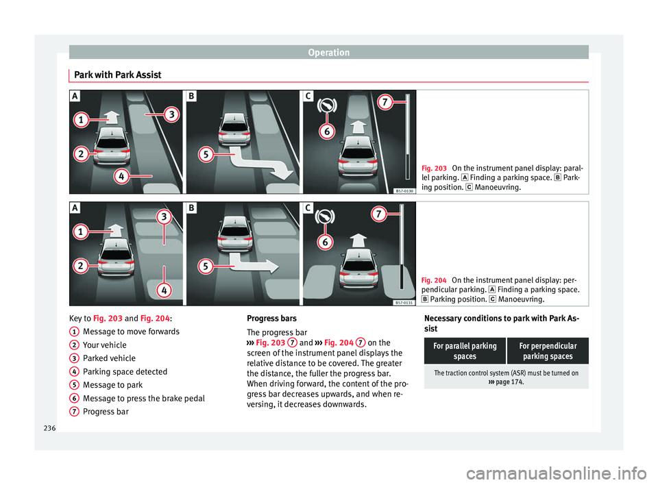
Park with Park Assist Fig. 203
On the instrument panel display: paral-
l el
parking. Finding a parking space. Park-
ing position. Manoeuvring. Fig. 204
On the instrument panel display: per-
pendic u
lar parking. Finding a parking space.
Parking position. Manoeuvring. Key to
Fig. 203 and Fig. 204:
M e
ssage to move forwards
Your vehicle
Parked vehicle
Parking space detected
Message to park
Message to press the brake pedal
Progress bar
1 2
3
4
5
6
7 Progress bars
The pr
ogr
ess bar
››› Fig. 203 7 and
›››
Fig. 204 7 on the
s c
reen of the instrument panel displays the
relative distance to be covered. The greater
the distance, the fuller the progress bar.
When driving forward, the content of the pro-
gress bar decreases upwards, and when re-
versing, it decreases downwards. Necessary conditions to park with Park As-
si
st
For parallel parking spacesFor perpendicularparking spaces
The traction control system (ASR) must be turned on ››› page 174. 236
Page 240 of 328
Operation
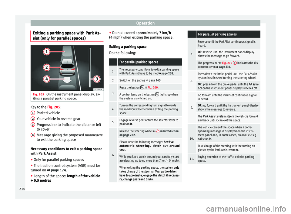
Exiting a parking space with Park As-
s i
st (only for parallel spaces) Fig. 205
On the instrument panel display: ex-
itin g a p
arallel parking space. Key to the
Fig. 205:
P ark
ed vehicle
Your vehicle in reverse gear
Progress bar to indicate the distance left
to cover
Message giving the proposed manoeuvre
to exit the parking space
Necessary conditions to exit a parking space
with Park Assist
● Only for parallel parking spaces
● The traction control system (ASR) must be
turned on ›
›› page 174.
● Length of the space: len
gth of the vehicle
+ 0.5 metres 1 2
3
4 ●
Do not e
xceed approximately 7 km/h
(4 mph) when exiting the parking space.
Exiting a parking space
Do the following:
For parallel parking spaces
1.The necessary conditions to exit a parking space
with Park Assist have to be met ››› page 238.
2.Switch on the engine ››› page 165.
3.
Press the button ››› Fig. 200.
A control lamp on the button lights up when
the system is switched on.
4.Turn on the corresponding turn signal towards
the road you will enter when exiting the parking
space.
5.Engage reverse gear or turn the selector lever to
position R.
6.
Release the steering wheel ››› in Introduction
on page 232.
Please note the following message: Active
automatic steering. Watch out around
you.
While you keep watch around you, carefully start
accelerating up to no more than 7 km/h (4 mph).
When exiting the parking space, the system only
takes charge of the steering. You, as the driver,
have to accelerate, engage the clutch if necessa-
ry, change gears and brake.
For parallel parking spaces
7.
Reverse until the ParkPilot continuous signal is
heard.
OR: reverse until the instrument panel display
shows the message to go forward.
The progress bar ››› Fig. 205 3 indicates the dis-
tance to cover ››› page 236.
8.
Press down the brake pedal until the Park Assist
system has finished turning the steering wheel.
OR: press down the brake pedal until the sym-
bol on the instrument panel display switches off.
9.
Go forward until the ParkPilot continuous signal
is heard.
OR: go forward until the instrument panel display
shows the message to reverse.
The Park Assist system steers the vehicle forward
and back until it can exit the space.
10.
The vehicle can exit the space when a corre-
sponding message is displayed on the instru-
ment panel and, in some cases, an acoustic sig-
nal sounds.
Take charge of the steering with the turning an-
gle set by the Park Assist system.
11.Paying attention to the traffic, exit the parking
space. 238
Page 245 of 328
Driver assistance systems
Moreover, with the SEAT Media System
Plu s/Nav
i System radios, a yellow trail indi-
cates the vehicle's expected trajectory based
on the steering wheel angle.
Whenever the obstacle is located in the vehi-
cle’s direction of travel, the corresponding
audible warning will sound.
As the vehicle approaches an obstacle, the
segments are displayed closer to the vehicle.
When the penultimate segment is displayed,
this means that the vehicle has reached the
collision zone. In the collision zone, the ob-
stacles are represented in red, including
those out of the path. Do not continue to
move forward (or backward) ››› in Descrip-
tion on p ag
e 240, ››› in Description on
p ag
e 240 !
In the event the car is equipped with the Area
View system, visual indication of Park Assist
will appear depending on the selected view
in the Area View system.
Adjusting the display and audible
warnin
gs The settings for the display and audible
w
arnin
gs are controlled via the Easy Con-
nect*. Automatic activation
on – activat
es the Automatic activa-
tion option ››› page 242.
off – deactivates the Automatic ac-
tivation option ››› page 242.
Front volume*
Volume in the front and rear area.
Front sound settings/sharpness*
Frequency (tone) of the sound in the front
area.
Rear volume*
Volume in the rear area.
Rear sound settings/sharpness*
Frequency (tone) of the sound in the rear
area.
Adjust volume
With the parking aid switched on, the active
audio/video source volume will be reduced
to the intensity of the selected setting.
Error messages When the Parking Aid is activated or when it
i
s
switched on, if a message reporting a Park- ing aid error is displayed on the instrument
panel, ther
e is a fault in the system.
If the fault doesn't disappear before discon-
necting the ignition, next time that parking
aid is engaged in reverse, it will not be indi-
cated.
If there is a fault in the parking aid system a
message will appear on the instrument panel
indicating the error. In addition the key
LED will blink.
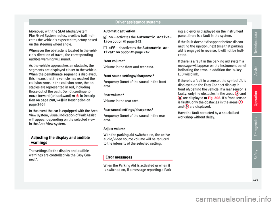
If there is a fault in a sensor, the symbol is
displayed on the Easy Connect display in
front of/behind the vehicle. If a rear sensor is
faulty, only the obstacles in the areas A and
B are displayed
››
› Fig. 206. If a front sensor
is faulty, only the obstacles in the areas C and
D are displayed.
Hav e the f
ault corrected by a specialised
workshop without delay.
243
Technical data
Advice
Operation
Emergencies
Safety
Page 250 of 328
Operation
CAUTION
● The c amer
a images are only two-dimen-
sional. Due to a lack of spatial depth, objects
that jut out or holes on the road, for example,
are more difficult to detect or may not be
seen at all.
● In certain circumstances, the camera does
not c
apture objects such as beams, fences,
posts or thin trees, which could damage the vehicle.
● The system displays the auxiliary lines and
box
es regardless of the vehicle's environ-
ment, no objects are detected. The driver is
responsible for determining that the vehicle
will fit in the parking space. CAUTION
In order to guarantee good system operation,
k eep the c
ameras clean, free of snow or ice,
and do not cover them with adhesives or oth-
er objects.
● Never use abrasive cleaning products to
cl
ean the camera lenses.
● Do not use hot or warm water to remove ice
or sno
w from the camera lenses. Doing so
could damage the lenses. Area View system
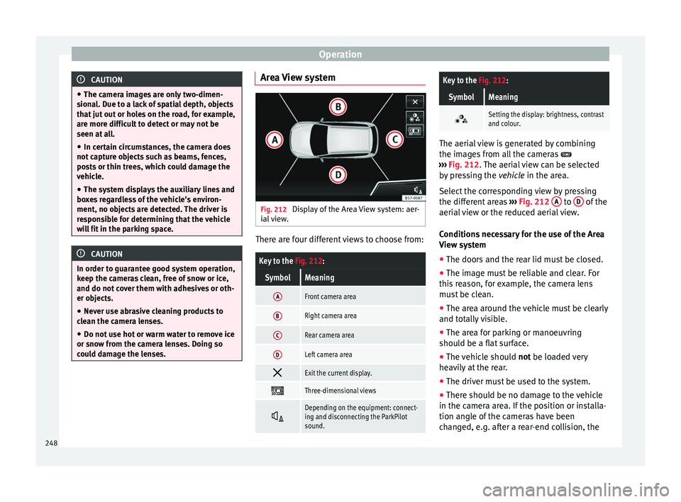
Fig. 212
Display of the Area View system: aer-
i al
view. There are four different views to choose from:
Key to the
Fig. 212:
SymbolMeaning
AFront camera area
BRight camera area
CRear camera area
DLeft camera area
Exit the current display.
Three-dimensional views
Depending on the equipment: connect-
ing and disconnecting the ParkPilot
sound.
Key to the
Fig. 212:
SymbolMeaning
Setting the display: brightness, contrast
and colour.
The aerial view is generated by combining
the im
ag
es from all the cameras
››› Fig. 212. The aerial view can be selected
by pressing the vehicle in the area.
Select the corresponding view by pressing
the different areas ››› Fig. 212 A to
D of the
aeri al
view or the reduced aerial view.
Conditions necessary for the use of the Area
View system
● The doors and the rear lid must be closed.
● The image must be reliable and clear. For
thi s
reason, for example, the camera lens
must be clean.
● The area around the vehicle must be clearly
and tot
ally visible.
● The area for parking or manoeuvring
shoul
d be a flat surface.
● The vehicle should not be loa
ded very
heavily at the rear.
● The driver must be used to the system.
● There should be no damage to the vehicle
in the camer
a area. If the position or installa-
tion angle of the cameras have been
changed, e.g. after a rear-end collision, the
248
Page 252 of 328
OperationExamples of optical illusions caused by the
cameras:
– If the vehicle approaches protruding objects. These
objects may be outside the cameras' angle of visibility.
Trailer mode
The Ar
e
a View system conceals, in the rear
camera area, all the auxiliary guiding lines
when the factory-fitted towing bracket is con-
nected electrically to a trailer ››› page 255. Note
In order to become familiar with the system
and it s
functions, SEAT recommends that you
practice handling the Area View system in an
area where there is not too much traffic or in
a car park. Menus of the Area View system (modes)
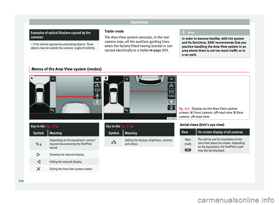
Fig. 214
Display on the Area View system
sc
reen: Front camera: off-road view Rear
camera: off-road view
Key to the Fig. 214:
SymbolMeaning
Depending on the equipment: connect-
ing and disconnecting the ParkPilot
sound.
Showing the reduced display.
Hiding the reduced display.
Exiting the Area View system screen:
Key to the
Fig. 214:
SymbolMeaning
Setting the display: brightness, contrast
and colour. Aerial views (bird's eye view)
ViewOn-screen display of all cameras
Main
mode
The vehicle and its immediate vicinity
seen from above are shown. Depending
on the equipment, the ParkPilot's path
may also be displayed. 250
Page 261 of 328
Towing bracket device*
WARNING
The incorrect use of the tow hitch with a bicy-
c l
e rack mounted on the tow hitch can cause
accidents and injury.
● Never exceed the maximum weight or the
limits
indicated above.
● The bicycle rack may not be mounted to the
neck
of the hitch below the ball because, due
to the shape of the neck and depending on
the rack model, the rack could be incorrectly
mounted on the vehicle.
● Always read and take the manufacturer as-
sembly
instructions into account. CAUTION
If the maximum weight and limits indicated
abo v
e are exceeded, the vehicle may suffer
considerable damage.
● Never exceed the values indicated! Note
SEAT recommends removing, as far as possi-
b l
e, all removable parts of the bicycles before
setting off. These parts include, for example,
baskets and saddlebags, child seats or bat-
teries. This improves aerodynamics and the
centre of gravity of the rack system. Hooking up and connecting a trailer
Fig. 218
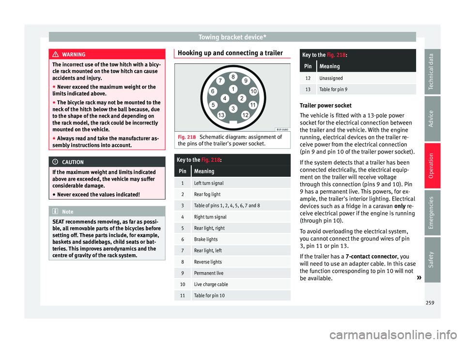
Schematic diagram: assignment of
the pins
of the trailer's power socket.
Key to the Fig. 218:
PinMeaning
1Left turn signal
2Rear fog light
3Table of pins 1, 2, 4, 5, 6, 7 and 8
4Right turn signal
5Rear light, right
6Brake lights
7Rear light, left
8Reverse lights
9Permanent live
10Live charge cable
11Table for pin 10
Key to the Fig. 218:
PinMeaning
12Unassigned
13Table for pin 9 Trailer power socket
The
v
ehicle is fitted with a 13-pole power
socket for the electrical connection between
the trailer and the vehicle. With the engine
running, electrical devices on the trailer re-
ceive power from the electrical connection
(pin 9 and pin 10 of the trailer power socket).
If the system detects that a trailer has been
connected electrically, the electrical equip-
ment on the trailer will receive voltage
through this connection (pins 9 and 10). Pin
9 has a permanent live. This powers, for ex-
ample, the trailer's interior lighting. Electrical
devices such as a fridge in a caravan only re-
ceive electrical power if the engine is running
(through pin 10).
To avoid overloading the electrical system,
you cannot connect the ground wires of pin
3, pin 11 or pin 13.
If the trailer has a 7-contact connector , you
will need to use an adapter cable. In this case
the function corresponding to pin 10 will not
be available. »
259
Technical data
Advice
Operation
Emergencies
Safety
Page 262 of 328
Operation
Tow rope
The t o
w rope must always be securely fixed
to the towing vehicle and loose enough so
that the vehicle can handle turns smoothly.
However, make sure that the cable does not
rub on the ground while driving.
Trailer rear lights
Always check the trailer's rear lights to en-
sure they are working correctly and that they
comply with the relevant safety regulations.
Make sure that the maximum permissible
power that can be absorbed by the trailer is
not exceeded ››› page 257.
Connection to the anti-theft system
The trailer is included in the anti-theft system
if the following conditions are met: ● If the vehicle is factory-equipped with an
anti-theft
alarm and towing bracket.
● If the trailer is electrically connected to the
to
wing vehicle through the trailer power
socket.
● If the electrical systems of the vehicle and
trai
ler are in perfect condition and have no
faults or damage.
● If the vehicle is locked with the key and the
anti-theft
alarm is activated.
When the vehicle is locked, the alarm is trig-
gered if the electrical connection with the
trailer is cut off. Before hitching or unhitching a trailer, always
turn off
the anti-theft alarm. Otherwise, the
tilt sensor could cause the alarm to go off.
Trailers with LED rear lights
For technical reasons, trailers fitted with LED
rear lights cannot be connected to the anti-
theft alarm system.
When the vehicle is locked, the alarm does
not go off when the electrical connection with
the trailer is cut if it has rear lights with light-
emitting diodes.
If the Eco driving profile was selected when
hitching the trailer, this will automatically
switch to the Normal profile. If the system
cannot detect the attached trailer or if the
towing bracket has been retrofitted by an au-
to repair shop other than SEAT, you must
manually select the Normal profile before you
start driving with a trailer attached. To recon-
nect the Eco profile once the trailer has been
unhitched, switch the ignition off and back
on once. WARNING
If the cables are improperly or incorrectly
c onnect
ed, it may lead to an excessive
amount of current supplied to the trailer,
which can cause abnormalities in the entire
vehicle electronic system, as well as acci-
dents and serious injuries. ●
En s
ure that any repairs that need to be car-
ried out on the electrical system are carried
out by a specialised workshop.
● Never connect the trailer's electric system
directly
to the electrical connections of the
tail lights or any other power sources. WARNING
Contact between the pins of the trailer power
soc k
et can cause short circuits, overloading
of the electrical system or failure of the light-
ing system, and consequently can cause acci-
dents and serious injuries.
● Never connect the pins of the trailer power
sock
et to each other.
● Make sure any work on bent pins is carried
out b
y a specialised workshop. CAUTION
Do not leave the trailer connected to the vehi-
c l
e when parked; place it on its support
wheel or its supports. If the vehicle rises or
falls due, for example, to a variation of the
load or a burst tyre, increased pressure will
be placed on the towing bracket and the trail-
er, and both the vehicle and the trailer can be
damaged. Note
● In c a
se of malfunctioning of the electrical
systems of the vehicle or trailer, as well as of 260