display Seat Ateca 2017 Owner's Guide
[x] Cancel search | Manufacturer: SEAT, Model Year: 2017, Model line: Ateca, Model: Seat Ateca 2017Pages: 328, PDF Size: 6.36 MB
Page 105 of 328
Instruments and warning/control lamps
engine hot. However, it is advisable to
c h
ange up a gear or move the selector
lever to D (or lift your foot off the acceler-
ator) before the needle reaches the red
zone ››› .
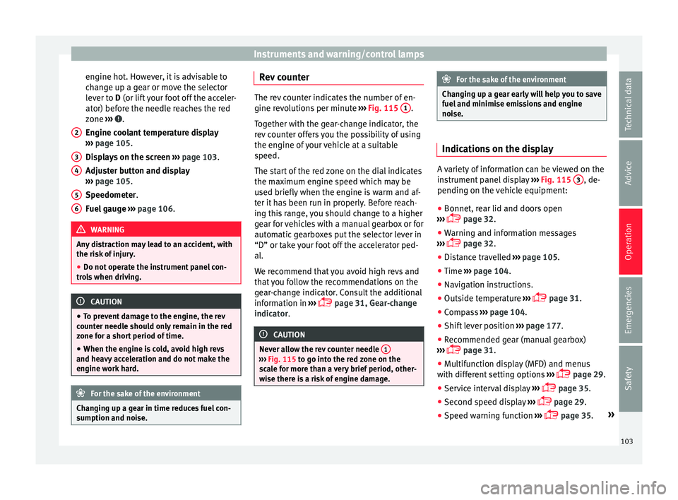
En gine c
oolant temperature display
››› page 105.
Displays on the screen ››› page 103.
Adjuster button and display
››› page 105.
Speedometer.
Fuel gauge ››› page 106. WARNING
Any distraction may lead to an accident, with
the ri sk
of injury.
● Do not operate the instrument panel con-
tro
ls when driving. CAUTION
● To pr
event damage to the engine, the rev
counter needle should only remain in the red
zone for a short period of time.
● When the engine is cold, avoid high revs
and heavy
acceleration and do not make the
engine work hard. For the sake of the environment
Changing up a gear in time reduces fuel con-
s umption and noi
se.2
3
4
5
6 Rev counter
The rev counter indicates the number of en-
gine r
ev
olutions per minute ››› Fig. 115 1 .
T og
ether with the gear-change indicator, the
rev counter offers you the possibility of using
the engine of your vehicle at a suitable
speed.
The start of the red zone on the dial indicates
the maximum engine speed which may be
used briefly when the engine is warm and af-
ter it has been run in properly. Before reach-
ing this range, you should change to a higher
gear for vehicles with a manual gearbox or for
automatic gearboxes put the selector lever in
“D” or take your foot off the accelerator ped-
al.
We recommend that you avoid high revs and
that you follow the recommendations on the
gear-change indicator. Consult the additional
information in ›››
page 31, Gear-change
indicator. CAUTION
Never allow the rev counter needle 1 ›››
Fig. 115 t o g
o into the red zone on the
scale for more than a very brief period, other-
wise there is a risk of engine damage. For the sake of the environment
Changing up a gear early will help you to save
f uel
and minimise emissions and engine
noise. Indications on the display
A variety of information can be viewed on the
in
s
trument panel display ››› Fig. 115 3 , de-
pendin g on the
vehicle equipment:
● Bonnet, rear lid and doors open
› ›
› page 32.
● Warning and information messages
››
› page 32.
● Distance travelled ››
›
page 105.
● Time ››
›
page 104.
● Navigation instructions.
● Outside temperature ››
›
page 31.
● Compass ››
›
page 104.
● Shift lever position ››
›
page 177.
● Recommended gear (manual gearbox)
››
› page 31.
● Multifunction display (MFD) and menus
with diff
erent setting options ›››
page 29.
● Service interval display ››
›
page 35.
● Second speed display ››
›
page 29.
● Speed warning function ››
›
page 35. »
103
Technical data
Advice
Operation
Emergencies
Safety
Page 106 of 328
Operation
● St ar
t-Stop system status display
››› page 188.
● Active cylinder management display
(ACT ®
)* ›
›› page 185
● Signs recognised by the traffic signal de-
tection sy
stem ››› page 228
● Low consumption driving status (ECO)
››
› page 104
● Identifying letters on engine (MKB).
Dis
tance travelled
The odometer registers the total distance
travelled by the car.
The odometer (trip ) shows the distance
travelled since the last odometer reset. The
last digit of the trip recorder indicates distan-
ces of 100 metres or one tenths of a mile.
● Briefly press the button ››
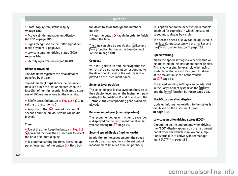
› Fig. 115 4 to re-
set the trip r
ecorder to 0.
● Keep the button 4 pressed for about 3
sec ond
s and the previous value will be dis-
played.
Time
● To set the time, keep the button ››
› Fig. 115
4 pressed for more than 3 seconds to select
the hour or minut e di
splay.
● To continue setting the time, press the up-
per or low
er part of the button 4 . Hold but-ton down to scroll through the numbers
quic
k
ly.
● Press the button 4 again in order to finish
settin g the time.
The time c
an also be set via the key and
Set up function button in the Easy Connect
sy s
tem ››› page 108.
Compass
With the ignition on and the navigation sys-
tem on, the cardinal point corresponding to
the direction of travel of the vehicle is dis-
played on the instrument panel.
Selector lever position
The selected gear is displayed on the side of
the selector lever and on the instrument pan-
el display. In positions D and S, and with the
Tiptronic, the corresponding gear is also dis-
played.
Recommended gear (manual gearbox)
The recommended gear in order to save fuel
is displayed on the instrument panel while
you are driving ›››
page 31.
Second speed display (mph or km/h)
In addition to the speedometer, the speed
can also be displayed in a different unit of
measurement (in miles or in km per hour). This option cannot be deactivated in models
des
tined for countries in which the second
speed must always be visible.
The second speed display can be adjusted in
the Easy Connect system via the key and
the Set
up function button
››
› page 108.
Speed warning
When the speed setting is exceeded, this will
be indicated on the instrument panel display.
This is very useful, for example when using
winter tyres that are not designed for driving
at the maximum speed of the vehicle
››› page 35.
The speed warning settings can be adjusted
in the Easy Connect system via the key
and the Set
up function button
››
› page 108.
Start-Stop operating display
Updated information relating to the status is
displayed on the instrument panel
››› page 188.
Low consumption driving status (ECO)*
Depending on the equipment, when driving,
the “ECO ” display appears on the instrument
panel when the vehicle is in low consump-
tion status due to active cylinder manage-
ment (ACT ®
)* ›››
page 185.
104
Page 107 of 328

Instruments and warning/control lamps
Identifying letters on engine (MKB)
Ho l
d the button ››› Fig. 115 4 down for more
th an 15 sec
onds to display the identifying
letters of the vehicle engine (MKB). To do
this, the ignition must be switched on and
the engine switched off. WARNING
Observe the safety warnings ››
› in Warning
and c ontr
ol lamps on page 107. WARNING
Even though outside temperatures are above
fr eez
ing, some roads and bridges may be icy.
● At outside temperatures above +4°C
(+39°F), even when the “ic
e crystal” symbol
is not visible, there may still be patches of ice
on the road.
● Do not rely on the outside temperature in-
dicat
or! Note
● Diff er
ent versions of the instrument panel
are available and therefore the versions and
instructions on the display may vary. In the
case of displays without warning or informa-
tion texts, faults are indicated exclusively by
the warning lamps.
● Depending on the equipment, some set-
ting
s and instructions can also be carried out
in the Easy Connect system. ●
When sev er
al warnings are active at the
same time, the symbols are shown succes-
sively for a few seconds and will stay on until
the fault is rectified. Odometer
Fig. 116
Instrument panel: odometer and re-
set b
utton. The distance covered is displayed in “kilome-
tr
e
s” or miles “m”. It is possible to change
the measurement units (kilometres
“km”/miles “m”) in the radio/Easy Connect*.
Please refer to the Easy Connect* Instructions
Manual for more details.
Odometer/trip recorder
The odometer shows the total distance cov-
ered by the vehicle.
The trip recorder shows the distance that has
been travelled since it was last reset. It is used to measure short trips. The last digit of
the trip rec
order indicates distances of 100
metres or tenths of a mile.
The trip recorder can be set to zero by press-
ing 0.0/SET
› ››
Fig. 116
.
Fault display
If there is a fault in the instrument panel, the
letters DEF will appear in the trip recorder
display. Have the fault repaired immediately,
as far as is possible.
Coolant temperature gauge For vehicles with no coolant temperature
g
aug
e, a control lamp appears for high
coolant temperatures ››› page 286. Please
note ››› .
The c oo
lant temperature gauge 2 ›››
Fig. 115 on ly
works when the ignition is
switched on. In order to avoid engine dam-
age, please read the following notes for the
different temperature ranges.
Engine cold
If only the diodes in the lower part of the
scale light up, this indicates that the engine
has not yet reached operating temperature.
Avoid high revs and heavy acceleration and
do not make the engine work hard. »
105
Technical data
Advice
Operation
Emergencies
Safety
Page 108 of 328
Operation
Normal temperature
If in norm
al operations, the diodes light up
until the central zone, it means that the en-
gine has reached operating temperature. At
high outside temperatures and when making
the engine work hard, the diodes may contin-
ue lighting up and reach the upper zone. This
is no cause for concern, provided the control
lamp does not light up on the instrument
panel digital display.
Heat range
When the diodes light up in the upper area of
the display and the control lamp appears
on the instrument panel display, the coolant
temperature is excessive ››› page 286. CAUTION
● To en
sure a long useful life for the engine,
avoid high revs, driving at high speed and
making the engine work hard for approxi-
mately the first 15 minutes when the engine
is cold. The phase until the engine is warm al-
so depends on the outside temperature. If
necessary, use the engine oil temperature*
››› page 34 as a guide.
● Additional lights and other accessories in
front
of the air inlet reduce the cooling effect
of the coolant. At high outside temperatures
and high engine loads, there is a risk of the
engine overheating.
● The front spoiler also ensures proper distri-
bution of
the cooling air when the vehicle is moving. If the spoiler is damaged this can re-
duc
e the c
ooling effect, which could cause
the engine to overheat. Seek specialist assis-
tance. Fuel level
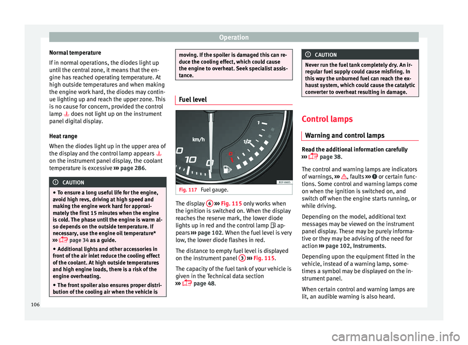
Fig. 117
Fuel gauge. The display
6
› ›
›
Fig. 115 only works when
the ignition is switched on. When the display
reaches the reserve mark, the lower diode
lights up in red and the control lamp ap-
pears ››› page 102. When the fuel level is very
low, the lower diode flashes in red.
The distance to empty fuel level is displayed
on the instrument panel 3
› ›
›
Fig. 115.
The capacity of the fuel tank of your vehicle is
given in the Technical data section
››› page 48. CAUTION
Never run the fuel tank completely dry. An ir-
r e
gular fuel supply could cause misfiring. In
this way the unburned fuel can reach the ex-
haust system, which could cause the catalytic
converter to overheat resulting in damage. Control lamps
W arnin
g and control lamps Read the additional information carefully
› ›
› page 38.
The control and warning lamps are indicators
of warnings, ››› , faults
››
› or certain func-
tion s.
Some control and warning lamps come
on when the ignition is switched on, and
switch off when the engine starts running, or
while driving.
Depending on the model, additional text
messages may be viewed on the instrument
panel display. These may be purely informa-
tive or they may be advising of the need for
action ›››
page 102, Instruments.
Depending upon the equipment fitted in the
vehicle, instead of a warning lamp, some-
times a symbol may be displayed on the in-
strument panel.
When certain control and warning lamps are
lit, an audible warning is also heard.
106
Page 110 of 328
Operation
Introduction to the Easy
C onnect
system*
System settings (CAR)* CAR menu (Setup) Read the additional information carefully
› ›
› page 26
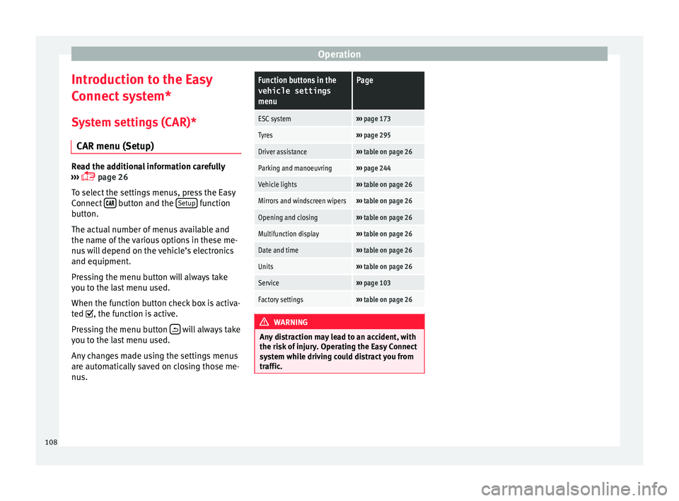
To select the settings menus, press the Easy
Connect button and the
Set
up function
b utt
on.
The actual number of menus available and
the name of the various options in these me-
nus will depend on the vehicle’s electronics
and equipment.
Pressing the menu button will always take
you to the last menu used.
When the function button check box is activa-
ted , the function is active.
Pressing the menu button will always take
y ou t
o the last menu used.
Any changes made using the settings menus
are automatically saved on closing those me-
nus.
Function buttons in the vehicle settings
menuPage
ESC system››› page 173
Tyres››› page 295
Driver assistance››› table on page 26
Parking and manoeuvring››› page 244
Vehicle lights››› table on page 26
Mirrors and windscreen wipers››› table on page 26
Opening and closing››› table on page 26
Multifunction display››› table on page 26
Date and time››› table on page 26
Units››› table on page 26
Service››› page 103
Factory settings››› table on page 26 WARNING
Any distraction may lead to an accident, with
the ri sk
of injury. Operating the Easy Connect
system while driving could distract you from
traffic. 108
Page 121 of 328
Opening and closing
CAUTION
The sensor surfaces on the door handles
c ou
ld engage if hit with a water jet or high
pressure steam if there is a valid vehicle key
in the proximity. If at least one of the win-
dows is open and the sensor surface B on
one of the h
andles permanently activates, all
windows will close. If the water jet or steam
is briefly moved away from the sensor surface A (arrow) on one of the handles and then
point ed at
it again, all the windows will prob-
ably open ››› page 118. Note
● If the
vehicle battery has little or no charge,
or the vehicle key battery is almost or entire-
ly out of charge, you will probably not be able
to lock or unlock the vehicle with the Keyless
Access system. The vehicle can be unlocked
or locked manually ››› page 85.
● To control the proper locking of the vehicle,
the rel
ease function is disabled for approx. 2
seconds.
● If the message Keyless access system
faulty is
displayed on the screen of the
dash panel, abnormalities may occur in the
operation of the Keyless Access system. Con-
tact a specialised workshop. SEAT recom-
mends visiting a SEAT dealership for this.
● Depending on the function set on the info-
tainment
system for the mirrors, the exterior
mirrors will unfold and the surround lighting
will come on when unlocking the vehicle us- ing the sensor surface on the driver and pas-
sen
g
er door handles ››› page 141.
● If there is no valid key inside the vehicle or
the sys
tem fails to detect one, a warning will
display on the dash panel screen. This could
happen if any other radio frequency signal in-
terferes with the key signal (e.g. from a mo-
bile device accessory) or if the key is covered
by another object (e.g. an aluminium case).
● If the sensors are very dirty, e.g. have a lay-
er of s
alt, how the sensors on the door han-
dles operate may be affected. In this case,
clean the vehicle.
● If the vehicle is equipped with an automatic
ge
arbox, it may only be locked in the gear
stick is in position P. Anti-theft security system (Safelock)*
The following message is displayed on the in-
s
trument
panel to remind the driver that
when the vehicle is closed from the outside,
the anti-theft security system is switched on. Do not forget the Safelock.
Please see Instruction Manual . The
vehicle cannot be opened from inside. This
makes it more difficult for unauthorised per-
sons to break into the vehicle ››› in De-
s c
ription on page 112.
The anti-theft security system can be switch-
ed off each time the vehicle is locked: ●
Turn the k
ey a second time to the lock posi-
tion, in the door lock, within two seconds. If
necessary, remove the protective cover on
the driver door handle ›››
page 9 or else
● Press on the remote control key for a
sec ond time
within 2 seconds.
The flashing frequency of the diode in the
door sill immediately confirms the process.
Initially, the diode flashes in a fast sequence
for a brief period, then it stops for approxi-
mately 30 seconds and, lastly continues
flashing slowly.
119Technical data
Advice
Operation
Emergencies
Safety
Page 135 of 328
Lights and visibility
When the system is activated and the camera
det ects
other vehicles that may be dazzled,
the main beam is automatically switched off.
Otherwise, the main beam is automatically
switched on.
The main beam assist generally detects illu-
minated areas and deactivates the main
beam when passing through a town, for ex-
ample.
Switching the main beam assist on and off
Func-
tionUse
Activate:
– Switch the ignition on and turn the light
switch to position .
– From the base position, move the main
beam and turn signal lever forwards
››› page 131. When the warning lamp
is
displayed on the instrument panel display,
the main beam assist is switched on.
To switch system off:
– Switch off the ignition.
– OR: turn the light switch to a different po-
sition to
››› page 131.
– OR: with main beam on, move the main
beam and turn signal lever backwards.
– OR: move the main beam and turn the
signal lever forwards to manually switch
the main beam on. The main beam assist
will then be deactivated. Malfunctions
The f
o
llowing conditions may prevent the
main beam headlight control from turning off the headlights in time or from turning off al-
tog
ether:
● In poorly lit towns with highly reflective
sign
s.
● Other insufficiently lit road users (such as
pedes
trians or cyclists).
● On tight bends and steep slopes (bumps)
and when oncomin
g vehicles are partially ob-
scured.
● When the drivers of other oncoming vehi-
cl
es (such as a truck) can see over a guard
rail in the centre of the road.
● If the camera is damaged or the power sup-
ply
is cut off.
● In fog, snow and heavy rain.
● With dust and sand turbulence.
● With loose gravel in the field of vision of
the camer
a.
● When the field of vision of the camera is
mis
ted up, dirty or covered by stickers, snow,
ice, etc. WARNING
The convenience features of the main beam
a s
sist should not encourage the taking of
risks. The system is not a replacement for
driver concentration.
● You are always in control of the main beam
and ad
apting it to the light, visibility and traf-
fic conditions. ●
It i
s possible that the main beam headlight
control does not recognise all driving situa-
tions and is limited under certain circumstan-
ces.
● When the field of vision of the camera is
dirty
, covered or damaged, operation of the
main beam control may be affected. This also
applies when changes are made to the vehi-
cle lighting system, for example, if additional
headlights are installed. CAUTION
To avoid affecting the operation of the sys-
t em, t
ake the following points into considera-
tion:
● Clean the field of vision of the camera regu-
larly
and make sure it is free of snow and ice.
● Do not cover the field of vision of the cam-
era.
● Chec
k that the windscreen is not damaged
in the are
a of the field of vision of the camera. Note
Main beam and headlight flasher can be
t urned on and off
manually at any time with
the turn signal and main beam lever
››› page 131. 133
Technical data
Advice
Operation
Emergencies
Safety
Page 160 of 328
OperationFunc-
tion
buttonFunction
OFFSwitch off and switch on the Climatronic.
SETUP
The air conditioning settings submenu is
opened. It is possible to make the following
adjustments:
Function button Air conditioning profile.
: to ad-
just the level of the fan in AUTO mode. You
can choose between low, medium and
high.
Function button Automatic air recirculation
to
switch on and off automatic air recircula-
tion ››› page 160.
BACK
function button to close the sub-
menu. Adjust using the Easy Connect sys-
t
em* 3 Ap
p
lies to vehicles with a Media System Plus/Navi
System.
In the Easy Connect system it is also possible
to perform various adjustments to the Clima-
tronic.
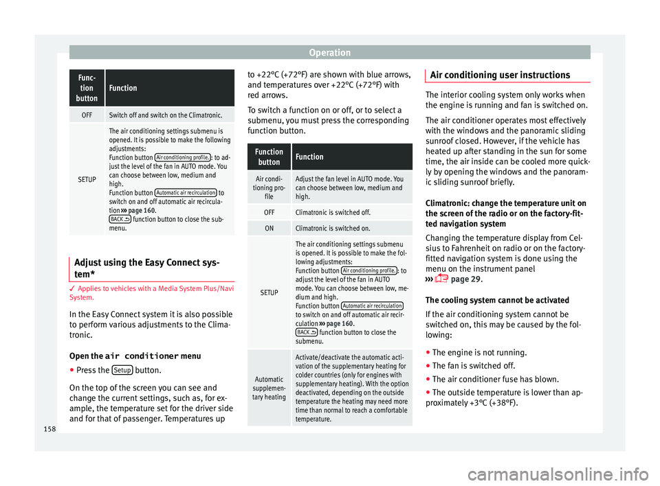
Open the air conditioner menu
● Press the Set
up button.
On the t op of
the screen you can see and
change the current settings, such as, for ex-
ample, the temperature set for the driver side
and for that of passenger. Temperatures up to +22°C (+72°F) are shown with blue arrows,
and temper
atures over +22°C (+72°F) with
red arrows.
To switch a function on or off, or to select a
submenu, you must press the corresponding
function button.
Function buttonFunction
Air condi-
tioning pro- fileAdjust the fan level in AUTO mode. You
can choose between low, medium and
high.
OFFClimatronic is switched off.
ONClimatronic is switched on.
SETUP
The air conditioning settings submenu
is opened. It is possible to make the fol-
lowing adjustments:
Function button Air conditioning profile.
: to
adjust the level of the fan in AUTO
mode. You can choose between low, me-
dium and high.
Function button Automatic air recirculation
to switch on and off automatic air recir-
culation
››› page 160.
BACK
function button to close the
submenu.
Automatic
supplemen-
tary heating
Activate/deactivate the automatic acti-
vation of the supplementary heating for
colder countries (only for engines with
supplementary heating). With the option
deactivated, depending on the outside
temperature the heating may need more
time than normal to reach a comfortable
temperature. Air conditioning user instructions
The interior cooling system only works when
the en
gine i
s running and fan is switched on.
The air conditioner operates most effectively
with the windows and the panoramic sliding
sunroof closed. However, if the vehicle has
heated up after standing in the sun for some
time, the air inside can be cooled more quick-
ly by opening the windows and the panoram-
ic sliding sunroof briefly.
Climatronic: change the temperature unit on
the screen of the radio or on the factory-fit-
ted navigation system
Changing the temperature display from Cel-
sius to Fahrenheit on radio or on the factory-
fitted navigation system is done using the
menu on the instrument panel
››› page 29.
The cooling system cannot be activated
If the air conditioning system cannot be
switched on, this may be caused by the fol-
lowing: ● The engine is not running.
● The fan is switched off.
● The air conditioner fuse has blown.
● The outside temperature is lower than ap-
pr o
ximately +3°C (+38°F).
158
Page 167 of 328

Driving
Driving St ar
t and stop the engine
Switching the ignition on and starting
the engine with the key Fig. 163
Ignition key positions. Read the additional information carefully
› ›
› page 23
Diesel engines can take a few seconds longer
than usual to start on cold days. Therefore
the clutch pedal (manual gearbox) or the
brake pedal (automatic gearbox) must re-
main pressed until the engine starts up. Dur-
ing preheating, the warning lamp remains
lit.
The preheating time depends on the coolant
and exterior temperatures. With the engine at
operating temperature, or at outside temper-
atures above +8°C, the warning lamp will light up for about one second. This means
that
the engine starts immediately.
If the engine does not immediately start up,
interrupt the starting process and try again
after 30 seconds. To start the engine again,
return the key to position 1 .
St ar
t-Stop System*
If the vehicle is stopped and the Start-Stop
system* switches off the engine, the ignition
remains switched on.
Automatic gearbox: before leaving the vehi-
cle, make sure that the ignition is switched
off and the selector lever is in position P.
Driver messages on the instrument panel
display
Press the clutch
This message appears on vehicles with a
manual gearbox if the driver tries to start the
engine without having the clutch pedal
pressed. The engine will only start if you
press the clutch pedal.
Press the brake This message appears on vehicles with an
automatic gearbox if the driver tries to start
the engine without having the brake pedal
pressed. Select N or P
This
message appears if you try to start or
stop the engine when the selector lever of
the automatic gearbox is not in position P or
N. The engine can only start or stop in certain
positions.
Engage position P; the vehicle
can move; doors can only close in
position P.For safety reasons, this driver message ap-
pears and an audible warning sounds if the
selector lever of the automatic gearbox is not
in position P after you switch off the ignition.
Put the selector lever in position P, otherwise
the vehicle could roll away.
Gear change: selector lever in
the drive position! This driver message is displayed when the
selector lever is not in the position P when
the driver door is opened. Additionally, a
buzzer will sound. Put the selector lever in
position P, otherwise the vehicle could roll
away.
Ignition is switched on
This driver message is displayed and a buz-
zer is sounded when the driver door is
opened with the ignition switched on. »
165
Technical data
Advice
Operation
Emergencies
Safety
Page 169 of 328
Driving
remains switched on. Make sure that the igni-
tion i
s
switched off before leaving the
vehicle, otherwise the battery could dis-
charge. Starter button*
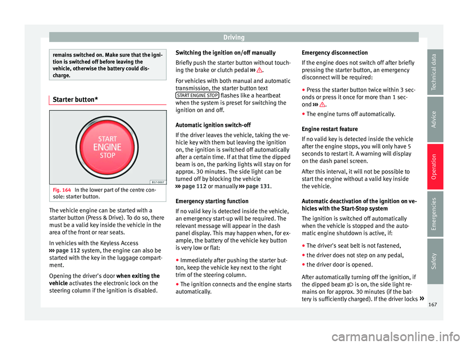
Fig. 164
In the lower part of the centre con-
so l
e: starter button. The vehicle engine can be started with a
s
t
arter button (Press & Drive). To do so, there
must be a valid key inside the vehicle in the
area of the front or rear seats.
In vehicles with the Keyless Access
››› page 112 system, the engine can also be
started with the key in the luggage compart-
ment.
Opening the driver's door when exiting the
vehicle activates the electronic lock on the
steering column if the ignition is disabled. Switching the ignition on/off manually
Briefly p
ush the starter button without touch-
ing the brake or clutch pedal ››› .
F or
vehicles with both manual and automatic
transmission, the starter button text START ENGINE STOP flashes like a heartbeat
when the sy s
tem is preset for switching the
ignition on and off.
Automatic ignition switch-off
If the driver leaves the vehicle, taking the ve-
hicle key with them but leaving the ignition
on, the ignition is switched off automatically
after a certain time. If at that time the dipped
beam is on, the parking lights will stay on for
approx. 30 minutes. The side light can be
turned off by blocking the vehicle
››› page 112 or manually ››› page 131.
Emergency starting function
If no valid key is detected inside the vehicle,
an emergency start-up will be required. The
relevant message will appear in the dash
panel display. This may happen when, for ex-
ample, the battery of the vehicle key button
is very low or flat: ● Immediately after pushing the starter but-
ton, k
eep the vehicle key next to the right
trim of the steering column.
● The ignition connects and the engine starts
autom
atically. Emergency disconnection
If the en
gine does not switch off after briefly
pressing the starter button, an emergency
disconnect will be required:
● Press the starter button twice within 3 sec-
onds
or press it once for more than 1 sec-
ond ››› .
● The engine turns off automatically.
En gine r
estart feature
If no valid key is detected inside the vehicle
after the engine stops, you will only have 5
seconds to restart it. A warning will display
on the dash panel screen.
After this interval, it will not be possible to
start the engine without a valid key inside
the vehicle.
Automatic deactivation of the ignition on ve-
hicles with the Start-Stop system
The ignition is switched off automatically
when the vehicle is stopped and the auto-
matic engine shutdown is active, if:
● The driver's seat belt is not fastened,
● the driver does not step on any pedal,
● the driver door is opened.
Aft
er automatically turning off the ignition, if
the dipped beam is on, the side light re-
mains on for approx. 30 minutes (if the bat-
tery is sufficiently charged). If the driver locks »
167
Technical data
Advice
Operation
Emergencies
Safety