bolt Seat Ateca 2017 Owner's Manual
[x] Cancel search | Manufacturer: SEAT, Model Year: 2017, Model line: Ateca, Model: Seat Ateca 2017Pages: 328, PDF Size: 6.36 MB
Page 56 of 328
The essentials
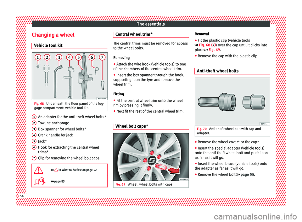
Changing a wheel V ehic
le tool kit Fig. 68
Underneath the floor panel of the lug-
g ag
e compartment: vehicle tool kit. An adapter for the anti-theft wheel bolts*
T
o
wline anchorage
Box spanner for wheel bolts*
Crank handle for jack
Jack*
Hook for extracting the central wheel
trims*
Clip for removing the wheel bolt caps.
››› in What to do first on page 52
››› page 83 1
2
3
4
5
6
7 Central wheel trim*
The central trims must be removed for access
t
o the wheel
bolts.
Removing
● Attach the wire hook (vehicle tools) to one
of the c
hambers of the central wheel trim.
● Insert the box spanner through the hook,
sup
porting it on the tyre and remove the
wheel trim.
Fitting
● Fit the central wheel trim onto the wheel
rim b y
pressing it firmly.
● Next fit the rest of the central wheel trim.
Wheel bolt caps* Fig. 69
Wheel: wheel bolts with caps. Removal
● Fit the plastic clip (vehicle tools
› ›
› Fig. 68 7 ) over the cap until it clicks into
p l
ace ››› Fig. 69.
● Remove the cap with the plastic clip.
Anti-theft wheel bolts Fig. 70
Anti-theft wheel bolt with cap and
a d
apter. ●
Remove the wheel cover* or the cap*.
● Insert the special adapter (vehicle tools)
ont o the anti-thef
t wheel bolt and push it on
as far as it will go.
● Insert the wheel brace (vehicle tools) onto
the ad
apter as far as it will go.
● Remove the wheel bolt ››
› page 55 .54
Page 57 of 328

The essentials
Note
Make a note of the code number of the anti-
thef t
wheel bolt and keep it in a safe place,
but not in your vehicle. If you need a new
adapter, you can obtain it from the SEAT Offi-
cial Service, indicating the code number. Loosening the wheel bolts
Fig. 71
Wheel: loosen the wheel bolts. ●
Insert the box spanner (vehicle tools) onto
the wheel bo
lt as far as it will go. An adapter
is required to unscrew or tighten the anti-
theft wheel bolts ›››
page 54.
● Turn the wheel bolt approximately one turn
to the l
eft ›››
Fig. 71 (arrow). To apply the re-
quired torque, hold the wheel brace at the
end. If it is not possible to loosen a wheel
bolt, carefully apply pressure with one foot
on the end of the box spanner. Hold on to the
vehicle for support and take care not to slip. WARNING
Slightly loosen the wheel bolts (one turn) be-
f or
e raising the vehicle with the jack*. If not,
an accident may occur. Lifting the vehicle
Fig. 72
Crossbar: marks. Fig. 73
Strut: mounting the jack on the vehi-
c l
e. ●
Plac
e the jack* (vehicle tools) on firm
ground. If necessary use a large, strong
board or similar support. If the surface is slip-
pery (for example tiles) place the jack on a
rubber mat or similar to prevent it from slip-
ping ››› .
● Find the support point on the strut (sunken
ar e
a) closest to the wheel to be changed
››› Fig. 72.
● Turn the jack* crank handle, located below
the strut
support point, to raise it until the
tab 1
› ››
Fig. 73
is below the housing provi-
ded.
● Align the jack* so that tab 1 “grips” onto
the hou s
ing provided on the strut and the
mobile base 2 is resting on the ground. The
b a
se plate 2 should fall vertically with re-
s pect
to the support point 1 .
● Continue turning the jack* until the wheel
i s
slightly lifted off the ground. WARNING
● Mak
e sure that the jack* remains stable. If
the surface is slippery or soft, the jack* could
slip or sink, respectively, with the resultant
risk of injury.
● Only raise the vehicle with the jack* sup-
plied b
y the manufacturer. Other vehicles
could slip, with the consequent risk of injury.
● Only mount the jack* on the support points
des
igned for this purpose on the strut, and
always align the jack correctly. If you do not, » 55
Page 58 of 328

The essentials
the jack* could slip as it does not have an
a
dequat
e grip on the vehicle: risk of injury!
● The height of the parked vehicle can
ch
ange as a result of variations in tempera-
ture and loading. CAUTION
The vehicle must not be raised on the cross-
b ar
. Only place the jack* on the points de-
signed for this purpose on the strut. Other-
wise, the vehicle may be damaged. Removing and fitting a wheel
Change the wheel after loosening the wheel
bo
lts
and raising the vehicle with the jack.
Taking off the wheel ● Unscrew the wheel bolts using the box
sp
anner and place them on a clean surface.
● Take off the wheel.
Puttin
g on the spare wheel
When fitting tyres with a compulsory rotation
direction, observe the instructions in
››› page 56.
● Mount the wheel.
● Screw on the wheel bolts in position and
tight en them loo
sely with a box spanner.
● Carefully lower the vehicle using the jack*. ●
Tight en the wheel
bolts in diagonal pairs
using the wheel brace.
The wheel bolts should be clean and turn
easily. Before fitting the spare wheel, inspect
the wheel condition and hub mounting surfa-
ces. These surfaces must be clean before fit-
ting the wheel.
Tyres with compulsory direction of ro-
tation A directional tread pattern can be identified
b
y
the arrows on the sidewall that point in
the direction of rotation. Always observe the
direction of rotation indicated when fitting
the wheel to guarantee optimum properties
of this type of tyres with regard to grip,
noises, wear and aquaplaning.
If it is absolutely necessary to fit the spare
tyre* against the direction of rotation, drive
with care as this means the tyre does not of-
fer optimum driving properties. This is of par-
ticular importance when the road surface is
wet.
To return to directional tread tires, replace
the punctured tyre as soon as possible and
restore the obligatory direction of rotation of
all tyres. Subsequent work ●
Alloy wheels: rep
lace the wheel bolt caps.
● Plate wheels: fit the c
entral wheel rim again
››› page 54.
● Return all tools to their proper storing loca-
tion.
● If the replaced wheel does not fit in the
sp
are wheel housing, store it safely in the
luggage compartment ›››
page 149.
● Check the tyre pressure of the newly moun-
ted ty
re as soon as possible.
● In vehicles fitted with a tyre pressure indi-
c at
or, adjust the pressure and store the read-
ing in the radio/Easy Connect system*
››› page 295.
● Have the tightening torque of the wheel
bolts
checked as soon as possible with a tor-
que wrench (it should be 140 Nm). Mean-
while, drive carefully.
● Have the flat tyre replaced as quickly as
pos
sible.
Snow chains Use Snow chains should only be used on the
fr
on
t wheels.56
Page 61 of 328
The essentials
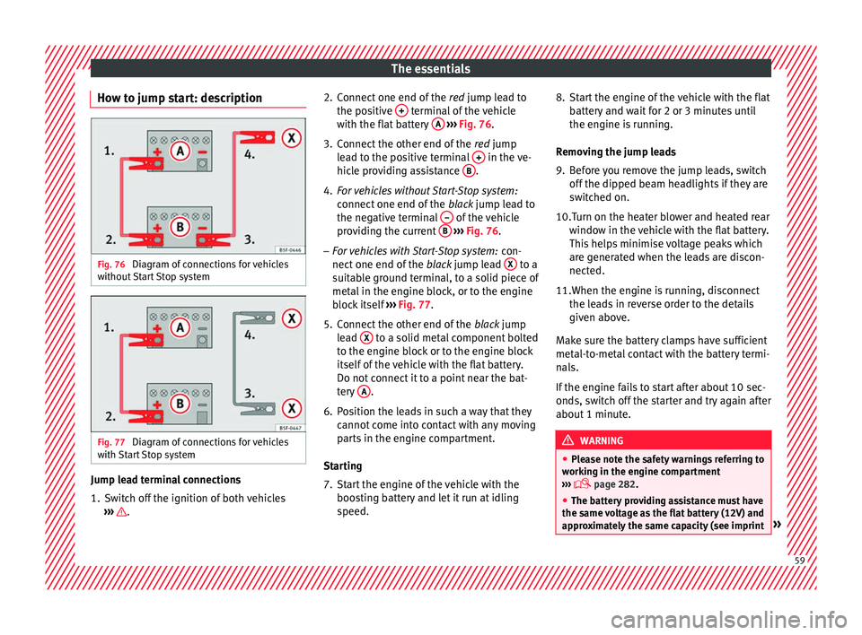
How to jump start: description Fig. 76
Diagram of connections for vehicles
w ithout
Start Stop system Fig. 77
Diagram of connections for vehicles
w ith
Start Stop system Jump lead terminal connections
1. Switch off the ignition of both vehicles
››
› . 2. Connect one end of the
re
d jump lead to
the positive + terminal of the vehicle
w ith the fl
at battery A
› ››
Fig. 76 .
3. Connect the other end of the re
d jump
lead to the positive terminal + in the ve-
hic l
e providing assistance B .
4. For vehicles without Start-Stop system:
connect
one end of the black jump lead to
the negative terminal – of the vehicle
pr o
viding the current B
› ››
Fig. 76 .
– For vehicles with Start-Stop system: con-
nect
one end of the black jump lead X to a
s uit
able ground terminal, to a solid piece of
metal in the engine block, or to the engine
block itself ››› Fig. 77.
5. Connect the other end of the blac
k jump
lead X to a solid metal component bolted
t o the en
gine block or to the engine block
itself of the vehicle with the flat battery.
Do not connect it to a point near the bat-
tery A .
6. Position the leads in such a way that they cannot
come into contact with any moving
parts in the engine compartment.
Starting
7. Start the engine of the vehicle with the boos
ting battery and let it run at idling
speed. 8. Start the engine of the vehicle with the flat
batt
ery and wait for 2 or 3 minutes until
the engine is running.
Removing the jump leads
9. Before you remove the jump leads, switch off the dip
ped beam headlights if they are
switched on.
10.Turn on the heater blower and heated rear windo
w in the vehicle with the flat battery.
This helps minimise voltage peaks which
are generated when the leads are discon-
nected.
11.When the engine is running, disconnect the le
ads in reverse order to the details
given above.
Make sure the battery clamps have sufficient
metal-to-metal contact with the battery termi-
nals.
If the engine fails to start after about 10 sec-
onds, switch off the starter and try again after
about 1 minute. WARNING
● Ple
ase note the safety warnings referring to
working in the engine compartment
››› page 282.
● The battery providing assistance must have
the same
voltage as the flat battery (12V) and
approximately the same capacity (see imprint » 59
Page 85 of 328
Self-help
Emergencies
Self -help
V
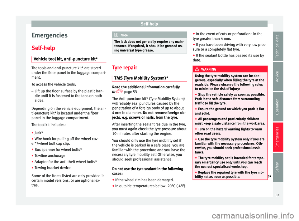
ehicle tool kit, anti-puncture kit* The tools and anti-puncture kit* are stored
u
nder the floor p
anel in the luggage compart-
ment.
To access the vehicle tools:
– Lift up the floor surface by the plastic han-
dl e u
ntil it is fastened to the tabs on both
sides.
Depending on the vehicle equipment, the an-
ti-puncture kit* is located under the floor
panel in the luggage compartment.
The tool kit includes:
● Jack*
● Wire hook for pulling off the wheel cov-
er*/wheel bo
lt cap clip.
● Box spanner for wheel bolts*
● Towline anchorage
● Adapter for the anti-theft wheel bolts*
● Towing bracket device
Some of the it
ems listed are only provided in
certain model versions, or are optional ex-
tras. Note
The jack does not generally require any main-
t en
ance. If required, it should be greased us-
ing universal type grease. Tyre repair
TM S
(Tyre Mobility System)* Read the additional information carefully
› ›
› page 53
The Anti-puncture kit* (Tyre Mobility System)
will reliably seal punctures caused by the
penetration of a foreign body of up to about
4 mm in diameter. Do not remove foreign ob-
jects, e.g. screws or nails, from the tyre.
After inserting the sealant residue in the tyre,
you must again check the tyre pressure about
10 minutes after starting the engine.
You should only use the tyre mobility set if
the vehicle is parked in a safe place, you are
familiar with the procedure and you have the
necessary tyre mobility set! Otherwise, you
should seek professional assistance.
Do not use the tyre sealant in the following
cases:
● If the wheel rim has been damaged.
● In outside temperatures below -20°C (-4°F). ●
In the ev ent
of cuts or perforations in the
tyre greater than 4 mm.
● If you have been driving with very low pres-
sur
e or a completely flat tyre.
● If the sealant bottle has passed its use by
dat
e. WARNING
Using the tyre mobility system can be dan-
g er
ous, especially when filling the tyre at the
roadside. Please observe the following rules
to minimise the risk of injury:
● Stop the vehicle safely as soon as possible.
Park
it at a safe distance from surrounding
traffic to fill the tyre.
● Ensure the ground on which you park is flat
and solid.
● A
ll passengers and particularly children
mus
t keep a safe distance from the work area.
● Turn on the hazard warning lights to warn
other ro
ad users.
● Use the tyre mobility system only if you are
fami
liar with the necessary procedures. Oth-
erwise, you should seek professional assis-
tance.
● The tyre mobility set is intended for tempo-
rar
y emergency use only until you can reach
the nearest specialised workshop.
● Replace the repaired tyre with the tyre mo-
bi
lity set as soon as possible. » 83
Technical data
Advice
Operation
Emergencies
Safety
Page 99 of 328
Fuses and bulbs
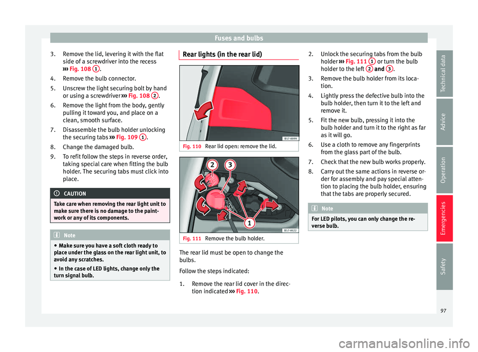
Remove the lid, levering it with the flat
s ide of
a screwdriver into the recess
››› Fig. 108 1 .
R emo
ve the bulb connector.
Unscrew the light securing bolt by hand
or using a screwdriver ››› Fig. 108 2 .
R emo
ve the light from the body, gently
pulling it toward you, and place on a
clean, smooth surface.
Disassemble the bulb holder unlocking
the securing tabs ››› Fig. 109 1 .
Ch an
ge the damaged bulb.
To refit follow the steps in reverse order,
taking special care when fitting the bulb
holder. The securing tabs must click into
place. CAUTION
Take care when removing the rear light unit to
m ak
e sure there is no damage to the paint-
work or any of its components. Note
● Mak
e sure you have a soft cloth ready to
place under the glass on the rear light unit, to
avoid any scratches.
● In the case of LED lights, change only the
turn s
ignal bulb. 3.
4.
5.
6.
7.
8.
9.
Rear lights (in the rear lid) Fig. 110
Rear lid open: remove the lid. Fig. 111
Remove the bulb holder. The rear lid must be open to change the
b
u
lbs.
Follow the steps indicated:
Remove the rear lid cover in the direc-
tion indicated ››› Fig. 110.
1. Unlock the securing tabs from the bulb
hol
der ››› Fig. 111 1 or turn the bulb
ho l
der to the left 2 and
3 .
R emo
ve the bulb holder from its loca-
tion.
Lightly press the defective bulb into the
bulb holder, then turn it to the left and
remove it.
Fit the new bulb, pressing it into the
bulb holder and turn it to the right as far
as it will go.
Use a cloth to remove any fingerprints
from the glass part of the bulb.
Check that the new bulb works properly.
Carry out the same actions in reverse or-
der for assembly and pay special atten-
tion to placing the bulb holder, ensuring
that the tabs are properly secured. Note
For LED pilots, you can only change the re-
v er
se bulb. 2.
3.
4.
5.
6.
7.
8.
97
Technical data
Advice
Operation
Emergencies
Safety
Page 158 of 328
Operation
Loading the roof carrier system The load can only be secured if the crossbars
and the r
oof
carrier system are properly in-
stalled ››› .
M ax
imum authorised roof load
The maximum permissible roof load is 75 kg.
This figure comes from the combined weight
of the roof carrier, the cross bars and the load
itself on the roof ››› .
A lw
ays check the weight of the roof carrier
system, the cross bars and the weight of the
load to be transported and weigh them if
necessary. Never exceed the maximum au-
thorised roof load.
If you are using cross bars and a roof carrier
with a lower weight rating, you will not be
able to carry the maximum authorised roof
load. In this case, do not exceed the maxi-
mum weight limit for the roof carrier which is
listed in the fitting instructions.
Distributing a load
Distribute loads uniformly and secure them
correctly ››› .
Chec k
attachments
Once the cross bars and roof carrier system
have been installed, check the bolted con-
nections and attachments after a short jour- ney and subsequently with a certain frequen-
cy. WARNING
Exceeding the maximum authorised roof load
c an r
esult in accidents and considerable vehi-
cle damage.
● Never exceed the maximum authorised
loa
d on the roof and on the axles or the vehi-
cle's maximum authorised weight.
● Never exceed the load capacity of the cross
bar
s and the roof carrier system, even if the
maximum authorised roof load has not been
reached.
● Secure heavy items as far forward as possi-
bl
e and distribute the vehicle load uniformly. WARNING
If the load is loose or not secured, it could fall
fr om the r
oof carrier system or cause acci-
dents and injuries.
● Always use belts or retaining straps that
are s
uitable and in a good condition.
● Secure the load properly. Air conditioning
He atin
g, ventilation and cool-
ing
Introduction Read the additional information carefully
› ›
› page 42
Viewing Climatronic information
On the screen of Climatronic control unit and
on the screen of the factory-fitted Easy Con-
nect system, the theoretical values of the
temperature zones are shown.
The unit of temperature measurement can be
changed in the Easy Connect system.
Dust and pollen filter
The dust and pollen filter with its activated
charcoal cartridge serves as a barrier against
impurities in the air taken into the vehicle in-
terior.
The dust and pollen filter must be changed
regularly so that air conditioner performance
is not adversely affected.
If the filter loses efficiency prematurely due
to use in areas with very high levels of air
pollution, the filter must be changed more
frequently than stated in the Service Sched-
ule.
156
Page 271 of 328
Care and maintenance
Carbon parts The carbon parts on your vehicle have a pain-
t
ed s
urface. They do not need any special
care and are cleaned just like any other pain-
ted part ››› page 266.
Paint damage Minor damage to the paint, such as scratches
or s
t
one chips, should be touched up without
delay before the metal starts to corrode. Suit-
able touch-up brushes or sprays for your car
can be obtained from a SEAT Official Service.
The number of the original paint finish on the
vehicle is given on the data sticker
››› page 301.
If corrosion is already visible it must be thor-
oughly removed by a specialised workshop.
Windows Clear vision is an essential safety factor.
The w
ind
screen must not be cleaned with in-
sect remover or wax, otherwise the wind-
screen wipers will not function properly (jud-
dering).
Traces of rubber, oil, grease or silicone can
be removed with a window cleaning solution
or a silicone remover. Wax residue can only be removed with a special cleaner. Your SEAT
Offic
ial Service will be able to provide you
with more detailed information.
The windows should also be cleaned on the
inside at regular intervals.
Use a separate cloth or chamois to dry the
windows. Cloths used for waxing and polish-
ing contain residues that will cause smears
on the glass. WARNING
Do not use water-repellent coatings on the
w ind
screen. In bad visibility conditions (e.g.
in the rain, dark or with a low sun), these
coatings may cause dazzle: risk of accident!
Such coatings can also cause the windscreen
wiper blades to make noise. CAUTION
● Remo
ve snow and ice from windows and ex-
terior mirrors with a plastic scraper only. To
avoid scratches caused by dirt on the glass,
the scraper should only be pushed in one di-
rection and not moved to and fro.
● The heating element for the rear window is
locat
ed on the inner side of the window. To
avoid damaging them, do not apply stickers
to these heating elements.
● Never use warm or hot water to remove
sno
w and ice from windows and mirrors. This
could cause the glass to crack! Wheels
The wheels require regular attention to pre-
ser
v
e their appearance. It is important to re-
move road salt and brake dust by washing
the wheels at regular intervals, otherwise the
finish will be impaired.
After washing, the wheels should only be
cleaned with an "acid-free" cleaning agent
for alloy wheels. This is available from SEAT
Official Services and specialist retailers. Nev-
er leave the cleaning agent on the rims for
any longer than specified in the instructions
before rinsing it off. If the wheel cleaner fluid
contains acid it can attack the surfaces of the
wheel bolts.
Car polish or other abrasive agents should
not be used for maintaining the rims. If the
protective coating is damaged, e.g. by flying
stones, the damaged area should be re-
paired immediately. WARNING
Please note when cleaning the wheels that
w at
er, ice and road salt can impair the effec-
tiveness of the brakes; this can cause an acci-
dent. Exhaust tail pipe
It is important to remove road salt and brake
du
s
t by washing the wheels at regular »
269
Technical data
Advice
Operation
Emergencies
Safety
Page 297 of 328
Wheels
●
Av
oid running the vehicle on tyres that are
more than 6 years old. If you have no alterna-
tive, you should drive slowly and with extra
care at all times.
● If wheel trims are fitted after the car is pur-
ch
ased, ensure that there is an adequate flow
of air for cooling the brake system. For the sake of the environment
Old tyres must be disposed of according to
the l a
ws in the country concerned. Note
● A S
EAT Service Centre should be consulted
to find out whether wheels or tyres of differ-
ent sizes to those originally fitted by SEAT
can be fitted, and to find out about the com-
binations allowed between the front axle
(axle 1) and the rear axle (axle 2).
● Never mount used tyres if you are not sure
of their
“previous history”.
● For technical reasons, it is not generally
pos
sible to use the wheels from other vehi-
cles. In some cases, this may also be true for
the same model of wheel. Wheel bolts
The wheel
bolts
ar
e matched to the rims.
When installing different wheels (for instance
alloy wheels or wheels with winter tyres) it is
important to use the correct wheel bolts with the right length and correctly shaped bolt
hea
ds. This ensures that wheels are fitted se-
curely and that the brake system functions
correctly.
The wheel bolts must be clean and turn easi-
ly.
A special adapter is required to turn the anti-
theft wheel bolts* ›››
page 54.
Tyre monitoring systems Introduction WARNING
Unsuitable handling of the wheels and tyres
m a
y lead to sudden tyre pressure losses, to
tread separation or even to a blow-out.
● Check tyre pressures regularly and ensure
they ar
e maintained at the pressures indica-
ted. Tyre pressure that is too low could cause
overheating, resulting in tread detachment or
even burst tyres.
● Tyre pressure should be that indicated on
the label
when the tyres are cold at all times
››› page 303.
● Regularly check the cold inflation pressure
of the ty
res. If necessary, change the tyre
pressure of the vehicle tyres while they are
cold. ●
Re
gularly check your tyres for damage and
wear.
● Never exceed the maximum permitted
speed or lo
ads specified for the type of tyre
fitted on your vehicle. For the sake of the environment
Under-inflated tyres lead to increased fuel
c on
sumption and tyre wear. Note
● Driv in
g for the first time with new tyres at a
high speed can cause them to slightly ex-
pand, which could then produce an air pres-
sure warning.
● Only replace used tyres with those author-
ised b
y SEAT for the corresponding type vehi-
cle.
● Do not only rely on the tyre monitoring sys-
tem. R
egularly check your tyres to ensure
that the tyre pressure is correct and that the
tyres are not damaged due to puncture, cuts,
tears and impacts/dents. Remove objects
from the tyres only when they have not
pierced the tyres. 295
Technical data
Advice
Operation
Emergencies
Safety
Page 305 of 328
Technical specifications
Trailer mode Tr
ailer weights Trailer weight
The tr
ai
ler weights and drawbar loads ap-
proved are selected in intensive trials accord-
ing to precisely defined criteria. The ap-
proved trailer weights are valid for vehicles in
the EU for maximum speeds of 80 km/h (50
mph) (in certain circumstances up to 100
km/h (62 mph)). The figures may be different
in other countries. All data in the official vehi-
cle documentation takes precedence over
these data at all times ››› .
Dr a
wbar loads
The maximum permitted drawbar load on the
ball joint of the towing bracket must not ex-
ceed 80 kg.
In the interest of road safety, we recommend
that you always tow approaching the maxi-
mum drawbar load. The response of the trail-
er on the road will be poor, if the drawbar
load is too small.
If the maximum permissible drawbar load
cannot be met (e.g. with small, empty and
light-weight single axle trailers or tandem
axle trailers with a wheelbase of less than 1
metre), a minimum of 4% of the actual trailer
weight is legally required for the drawbar
load. WARNING
● For s
afety reasons, you should not drive at
speeds above 80 km/h (50 mph) when towing
a trailer. This also applies in countries where
higher speeds are permitted.
● Never exceed the maximum trailer weights
or the dra
wbar load. If the permissible axle
load or the permissible total weight is excee-
ded, the driving characteristics of the vehicle
may change, leading to accidents, injuries
and damage to the vehicle. Wheels
Ty
re pressure, snow chains, wheel
bolts Tyre pressures
The s
tic
ker with the tyre pressure values can
be found on the inside of the fuel tank flap.
The tyre pressure values given there are for
cold tyres. The slightly raised pressures of
warm tyres must not be reduced. ››› The pressure for win
t
er tyres is 0.2 bar
(2.9 psi / 20 kPa) higher than that of summer
tyres.
Snow chains
Snow chains may be fitted only to the front
wheels, and only for the following tyres:
215/60 R16Chains with links of maximum 15 mm
215/55 R17Chains with links of maximum 15 mm
215/50 R18Chains with links of maximum 15 mm
Other dimensions do not allow chains Wheel bolts
Af
t
er the wheels have been changed, the
tightening torque of the wheel bolts should
be checked as soon as possible with a torque
wrench ››› . The tightening torque for steel
and al lo
y wheels is 140 Nm. WARNING
● Chec k
the tyre pressure at least once per
month. Checking the tyre pressure is very im-
portant. If the tyre pressure is too high or too
low, there is an increased danger of accidents
- particularly at high speeds.
● If the tightening torque of the wheel bolts
is
too low, they could loosen while the vehi-
cle is in motion. Risk of accident! If the tight-
ening torque is too high, the wheel bolts and
threads can be damaged. Note
We recommend that you ask your Technical
Ser v
ice for information about appropriate
wheel, tyre and snow chain size. 303
Technical data
Advice
Operation
Emergencies
Safety