key Seat Ateca 2018 Workshop Manual
[x] Cancel search | Manufacturer: SEAT, Model Year: 2018, Model line: Ateca, Model: Seat Ateca 2018Pages: 348, PDF Size: 7.32 MB
Page 246 of 348
OperationDriving
profileCharacteristics
Eco
Places the vehicle in a particularly low
state of consumption, facilitating a fuel-
saving driving style that is respectful to
the environment.
NormalOffers a balanced driving experience,
suitable for everyday use.
SportProvides a complete dynamic perform-
ance in the vehicle, enabling the user a
more sporty driving style.
Individ- ualIt allows you to personalise the configura-
tion. The functions that can be adjusted
depend on the equipment fitted in the ve-
hicle.
Offroad a)It adjusts the vehicle's parameters in or-
der to maintain optimal off-road driving.
Snowa)It adjusts the vehicle's behaviour for driv-
ing on slippery road surfaces, optimising
grip and manoeuvrability.
a)
Only for 4Drive models. WARNING
When operating SEAT Drive Profile, pay atten-
tion to a l
l traffic: doing otherwise could cause
an accident. Note
● When the v ehic
le is switched off it will al-
ways store the driving profile that was selec-
ted when the ignition key was removed. Nev- ertheless, when the engine is restarted, the
engine and the g
e
ar will not restart in the set-
ting selected. For engine and gear to revert to
the desired position, select the correspond-
ing drive profile again or press the Easy Con-
nect system button repeatedly.
● When the vehicle is restarted after using
the Offroad or Snow settings, the sy
stem is
always activated in the Normal profile.
● Your speed and driving style must always
be adjus
ted to visibility, weather, and traffic
conditions.
● The Eco profile is not recommended when
to
wing a vehicle. Kick-down
The Kick-down feature allows maximum ac-
c
el
er
ation to be reached.
If the Eco* profile has been selected in the
SEAT Drive Profile ››› page 243 and the
accelerator is pressed beyond a hard point,
the engine power is automatically controlled
to give your vehicle maximum acceleration. WARNING
Please note that if the road surface is slip-
pery or w
et, the kick-down feature could
cause the driving wheels to spin, which could
result in skidding. 244
Page 256 of 348
Operation
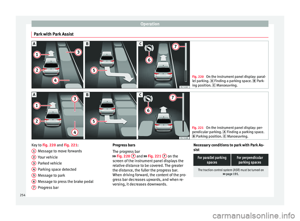
Park with Park Assist Fig. 220
On the instrument panel display: paral-
lel p
arking. Finding a parking space. Park-
ing position. Manoeuvring. Fig. 221
On the instrument panel display: per-
pendicu l
ar parking. Finding a parking space.
Parking position. Manoeuvring. Key to
Fig. 220 and Fig. 221:
M e
s
sage to move forwards
Your vehicle
Parked vehicle
Parking space detected
Message to park
Message to press the brake pedal
Progress bar
1 2
3
4
5
6
7 Progress bars
The pr
ogr
e
ss bar
››› Fig. 220 7 and
›››
Fig. 221 7 on the
s c
r
een of the instrument panel displays the
relative distance to be covered. The greater
the distance, the fuller the progress bar.
When driving forward, the content of the pro-
gress bar decreases upwards, and when re-
versing, it decreases downwards. Necessary conditions to park with Park As-
sis
t
For parallel parking spacesFor perpendicularparking spaces
The traction control system (ASR) must be turned on ››› page 191. 254
Page 258 of 348
Operation
Exiting a parking space with Park As-
s i
s
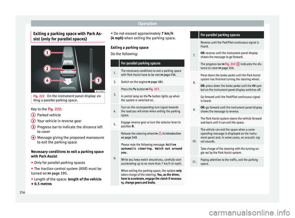
t (only for parallel spaces) Fig. 222
On the instrument panel display: ex-
itin g a p
ar
allel parking space. Key to the
Fig. 222:
P ark
ed
vehicle
Your vehicle in reverse gear
Progress bar to indicate the distance left
to cover
Message giving the proposed manoeuvre
to exit the parking space
Necessary conditions to exit a parking space
with Park Assist
● Only for parallel parking spaces
● The traction control system (ASR) must be
turned on ››
› page 191.
● Length of the space: leng
th of the vehicle
+ 0.5 metres 1 2
3
4 ●
Do not e
x
ceed approximately 7 km/h
(4 mph) when exiting the parking space.
Exiting a parking space
Do the following:
For parallel parking spaces
1.The necessary conditions to exit a parking space
with Park Assist have to be met ››› page 256.
2.Switch on the engine ››› page 181.
3.
Press the button ››› Fig. 217.
A control lamp on the button lights up when
the system is switched on.
4.Turn on the corresponding turn signal towards
the road you will enter when exiting the parking
space.
5.Engage reverse gear or turn the selector lever to
position R.
6.
Release the steering wheel ››› in Introduction
on page 249.
Please note the following message: Active
automatic steering. Watch out around
you.
While you keep watch around you, carefully start
accelerating up to no more than 7 km/h (4 mph).
When exiting the parking space, the system only
takes charge of the steering. You, as the driver,
have to accelerate, engage the clutch if necessa-
ry, change gears and brake.
For parallel parking spaces
7.
Reverse until the ParkPilot continuous signal is
heard.
OR: reverse until the instrument panel display
shows the message to go forward.
The progress bar ››› Fig. 222 3 indicates the dis-
tance to cover ››› page 254.
8.
Press down the brake pedal until the Park Assist
system has finished turning the steering wheel.
OR: press down the brake pedal until the sym-
bol on the instrument panel display switches off.
9.
Go forward until the ParkPilot continuous signal
is heard.
OR: go forward until the instrument panel display
shows the message to reverse.
The Park Assist system steers the vehicle forward
and back until it can exit the space.
10.
The vehicle can exit the space when a corre-
sponding message is displayed on the instru-
ment panel and, in some cases, an acoustic sig-
nal sounds.
Take charge of the steering with the turning an-
gle set by the Park Assist system.
11.Paying attention to the traffic, exit the parking
space. 256
Page 263 of 348
Driver assistance systems
obstacles that are less than
30 c m a
w
ay from the vehicle are dis-
played in red.
Moreover, with the SEAT Media System
Plus/Navi System/Navi System Plus radios, a
yellow trail indicates the vehicle's expected
trajectory based on the steering angle.
Whenever the obstacle is located in the vehi-
cle’s direction of travel, the corresponding
audible warning will sound.
As the vehicle approaches an obstacle, the
segments are displayed closer to the vehicle.
When the penultimate segment is displayed,
this means that the vehicle has reached the
collision zone. In the collision zone, the ob-
stacles are represented in red, including
those out of the path. Do not continue to
move forward (or backward) ››› in Descrip-
tion on p ag
e 258
, ››› in Description on
p ag
e 258
!
In the event the car is equipped with the Top
View Camera system, Park Assist visual guid-
ance will appear in accordance with the view
selected in the Top View Camera system.
Adjusting the display and audible
warning
s The settings for the display and audible
w
arnin g
s are controlled via the Easy Con-
nect*. Red segments: Automatic activation
on – activate
s the Automatic activa-
tion option ››› page 260.
off – deactivates the Automatic ac-
tivation option ››› page 260.
Front volume*
Volume in the front and rear area.
Front sound settings/sharpness*
Frequency (tone) of the sound in the front
area.
Rear volume*
Volume in the rear area.
Rear sound settings/sharpness*
Frequency (tone) of the sound in the rear
area.
Adjust volume
With the parking aid switched on, the active
audio/video source volume will be reduced
to the intensity of the selected setting.
Error messages When the Parking Aid is activated or when it
i
s
sw
itched on, if a message reporting a Park- ing aid error is displayed on the instrument
panel, there i
s a fault in the system.
If the fault does not disappear before discon-
necting the ignition, the next time that the
parking aid is engaged in reverse, no audible
signal of the existence of a fault will be is-
sued.
If there is a fault in the parking aid system a
message will appear on the instrument panel
indicating the error. In addition the key
LED will blink.
If there is a fault in a sensor, the symbol is
displayed on the Easy Connect display in
front of/behind the vehicle. If a rear sensor is
faulty, only the obstacles in area A are dis-
p l
a
yed ››› Fig. 223. If a front sensor is faulty,
only the obstacles in area B are displayed.
Hav e the f
au
lt corrected by a specialised
workshop without delay.
261
Technical data
Advice
Operation
Emergencies
Safety
Page 269 of 348
Driver assistance systems
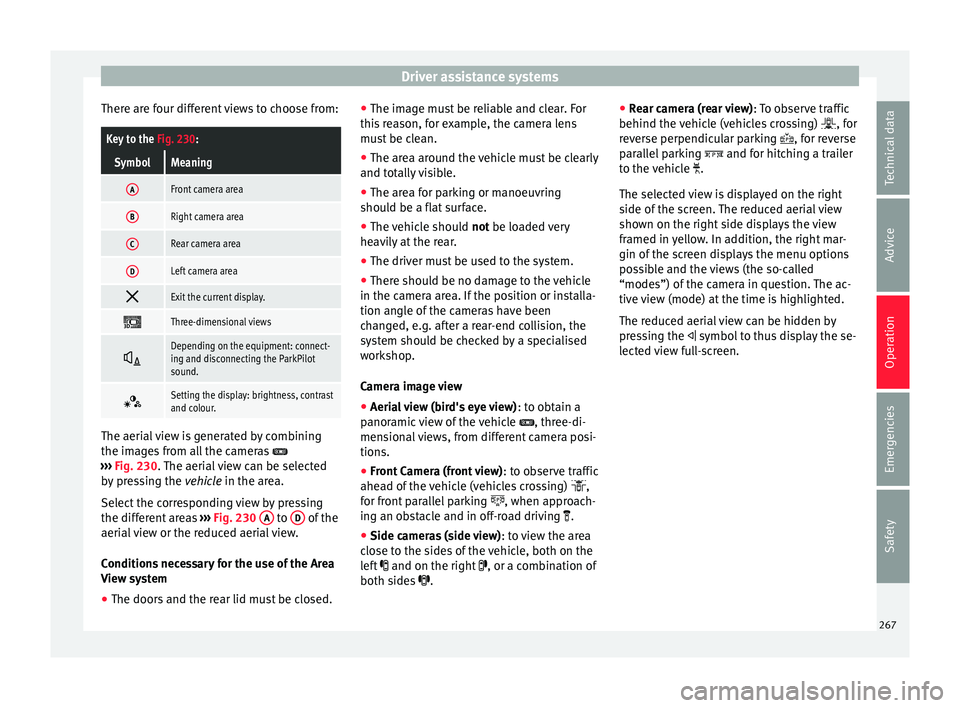
There are four different views to choose from:Key to the Fig. 230:
SymbolMeaning
AFront camera area
BRight camera area
CRear camera area
DLeft camera area
Exit the current display.
Three-dimensional views
Depending on the equipment: connect-
ing and disconnecting the ParkPilot
sound.
Setting the display: brightness, contrast
and colour.
The aerial view is generated by combining
the im
ag
e
s from all the cameras
››› Fig. 230. The aerial view can be selected
by pressing the vehicle in the area.
Select the corresponding view by pressing
the different areas ››› Fig. 230 A to
D of the
aeri al
view or the reduced aerial view.
Conditions necessary for the use of the Area
View system
● The doors and the rear lid must be closed. ●
The image mu
st be reliable and clear. For
this reason, for example, the camera lens
must be clean.
● The area around the vehicle must be clearly
and total
ly visible.
● The area for parking or manoeuvring
should be a fl
at surface.
● The vehicle should not be loaded
very
heavily at the rear.
● The driver must be used to the system.
● There should be no damage to the vehicle
in the camera ar
ea. If the position or installa-
tion angle of the cameras have been
changed, e.g. after a rear-end collision, the
system should be checked by a specialised
workshop.
Camera image view
● Aerial view (bird's eye view) : to obt
ain a
panoramic view of the vehicle , three-di-
mensional views, from different camera posi-
tions.
● Front Camera (front view) : to ob
serve traffic
ahead of the vehicle (vehicles crossing) ,
for front parallel parking , when approach-
ing an obstacle and in off-road driving .
● Side cameras (side view) : to v
iew the area
close to the sides of the vehicle, both on the
left and on the right , or a combination of
both sides . ●
Rear c
amera (rear view) : To observe traffic
behind the vehicle (vehicles crossing) , for
reverse perpendicular parking , for reverse
parallel parking and for hitching a trailer
to the vehicle .
The selected view is displayed on the right
side of the screen. The reduced aerial view
shown on the right side displays the view
framed in yellow. In addition, the right mar-
gin of the screen displays the menu options
possible and the views (the so-called
“modes”) of the camera in question. The ac-
tive view (mode) at the time is highlighted.
The reduced aerial view can be hidden by
pressing the symbol to thus display the se-
lected view full-screen.
267
Technical data
Advice
Operation
Emergencies
Safety
Page 271 of 348
Driver assistance systems
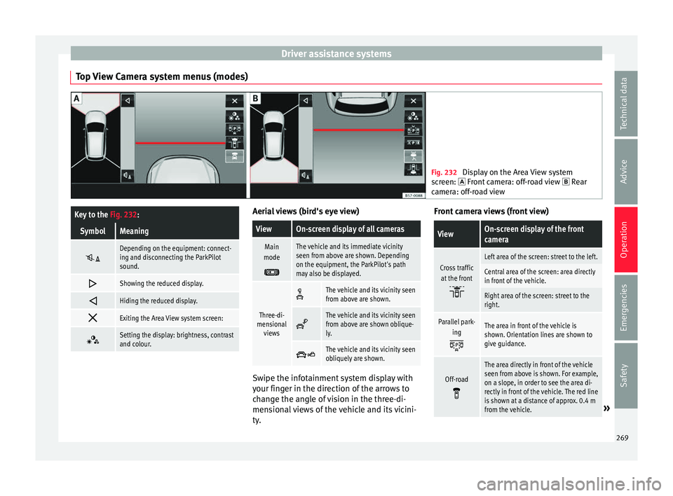
Top View Camera system menus (modes) Fig. 232
Display on the Area View system
sc r
een: Front camera: off-road view Rear
camera: off-road view
Key to the Fig. 232:
SymbolMeaning
Depending on the equipment: connect-
ing and disconnecting the ParkPilot
sound.
Showing the reduced display.
Hiding the reduced display.
Exiting the Area View system screen:
Setting the display: brightness, contrast
and colour. Aerial views (bird's eye view)
ViewOn-screen display of all cameras
Main
mode
The vehicle and its immediate vicinity
seen from above are shown. Depending
on the equipment, the ParkPilot's path
may also be displayed.
Three-di-
mensional views
The vehicle and its vicinity seen
from above are shown.
The vehicle and its vicinity seen
from above are shown oblique-
ly.
The vehicle and its vicinity seen
obliquely are shown.
Swipe the infotainment system display with
y
our fin
g
er in the direction of the arrows to
change the angle of vision in the three-di-
mensional views of the vehicle and its vicini-
ty. Front camera views (front view)
ViewOn-screen display of the front
camera
Cross traffic
at the front
Left area of the screen: street to the left.
Central area of the screen: area directly
in front of the vehicle.
Right area of the screen: street to the
right.
Parallel park- ing
The area in front of the vehicle is
shown. Orientation lines are shown to
give guidance.
Off-road
The area directly in front of the vehicle
seen from above is shown. For example,
on a slope, in order to see the area di-
rectly in front of the vehicle. The red line
is shown at a distance of approx. 0.4 m
from the vehicle.
» 269
Technical data
Advice
Operation
Emergencies
Safety
Page 280 of 348

Operation
Hooking up and connecting a trailer Fig. 236
Schematic diagram: assignment of
the pins of the trailer's power socket.
Key to the Fig. 236:
PinMeaning
1Left turn signal
2Rear fog light
3Earth for pins 1, 2, 4, 5, 6, 7 and 8
4Right turn signal
5Rear light, right
6Brake lights
7Rear light, left
8Reverse lights
9Permanent live
10Live charge cable
11Earth for pin 10
Key to the Fig. 236:
PinMeaning
12Unassigned
13Earth for pin 9 Trailer power socket
The v
ehic
le is fitted with a 13-pole power
socket for the electrical connection between
the trailer and the vehicle. With the engine
running, electrical devices on the trailer re-
ceive power from the electrical connection
(pin 9 and pin 10 of the trailer power socket).
If the system detects that a trailer has been
connected electrically, the electrical equip-
ment on the trailer will receive voltage
through this connection (pins 9 and 10). Pin
9 has a permanent live. This powers, for ex-
ample, the trailer's interior lighting. Electrical
devices such as a fridge in a caravan only re-
ceive electrical power if the engine is running
(through pin 10).
To avoid overloading the electrical system,
you cannot connect the ground wires of pin
3, pin 11 or pin 13.
If the trailer has a 7-contact connector , you
will need to use an adapter cable. In this case
the function corresponding to pin 10 will not
be available. Tow rope
The to
w r
ope must always be securely fixed
to the towing vehicle and loose enough so
that the vehicle can handle turns smoothly.
However, make sure that the cable does not
rub on the ground while driving.
Trailer rear lights
Always check the trailer's rear lights to en-
sure they are working correctly and that they
comply with the relevant safety regulations.
Make sure that the maximum permissible
power that can be absorbed by the trailer is
not exceeded ››› page 276.
Connection to the anti-theft system
The trailer is included in the anti-theft system
if the following conditions are met: ● If the vehicle is factory-equipped with an
anti-theft al
arm and towing bracket.
● If the trailer is electrically connected to the
tow
ing vehicle through the trailer power
socket.
● If the electrical systems of the vehicle and
trail
er are in perfect condition and have no
faults or damage.
● If the vehicle is locked with the key and the
anti-theft al
arm is activated.
When the vehicle is locked, the alarm is trig-
gered if the electrical connection with the
trailer is cut off.
278
Page 291 of 348
Care and maintenance
WARNING
Please note when cleaning the wheels that
wat er
, ice and road salt can impair the effec-
tiveness of the brakes; this can cause an acci-
dent. Exhaust pipe
It is important to remove road salt and brake
dus
t
by washing the wheels at regular inter-
vals, otherwise the exhaust tail pipe material
could be damaged. To remove impurities, do
not use rim, paint or chrome cleaners or oth-
er abrasive products. Clean the exhaust tail
pipes with cleaning products that are suita-
ble for stainless steel.
SEAT Official Services carry stocks of cleaning
products that have been tested and ap-
proved for use on your vehicle.
Caring for the vehicle interior Scr een f
or the radio/Easy Connect*
and control panel* The display can be cleaned with a soft cloth
and a pr
of
e
ssionally available “LCD cleaner”.
Moisten the cloth with a small amount of the
cleaning fluid. The Easy Connect control panel* should first
be cle
aned with a brush so that no dirt goes
into the device or between the keys and
housing. Next, we recommend cleaning the
Easy Connect control panel* using a cloth
dampened with water and washing-up liquid. CAUTION
● To av oid s
cratching the screen, do not wipe
the display with a dry cloth.
● To avoid damage, ensure that no liquid
goes
into the Easy Connect control panel*. Plastic and leatherette parts
Plastic parts and leatherette can be cleaned
w
ith a d
amp c
loth. If this is not sufficient,
plastic parts and leatherette should only be
treated with a special solvent-free plastic
cleaner.
Textile covers and trim parts Textile covers and trim parts (e.g. seats, door
trim) shou
l
d be c
leaned regularly with a vac-
uum cleaner. This will remove surface dirt
which could otherwise be rubbed into the
textile material during use. Do not use steam
cleaners, as the steam could carry the dirt
deeper into the textile material. Normal cleaning
We rec
ommend that you use a soft sponge or
a commercially available lint-free, micro-fibre
cloth for normal cleaning. Only use brushes
on floor coverings and mats, as other textile
surfaces could become damaged.
In the case of normal surface dirt you can use
a foam cleaner. Use a sponge to spread the
foam on the textile surface and to work it into
the material lightly. However, make sure that
the textile material does not become soaking
wet. Then dab off the foam with a dry and ab-
sorbent cloth (e.g. a micro-fibre cloth) and
vacuum off any residue once the surface is
completely dry.
Cleaning stains
Treat drink stains (such as coffee or fruit
juice, etc.) with a cleaning solution for deli-
cate fabrics. This solution should be applied
with a sponge. If the stains are difficult to re-
move, a washing paste can be applied direct-
ly onto the stain and worked into the fabric.
The surface will then have to be wiped with
clear water to remove any residue left by the
paste. To do so, use a damp cloth or sponge
and then dab the stain with an absorbent
cloth.
Remove chocolate or make-up stains with a
cleaning paste (for e.g., soft soap). Then re-
move the soap with water (wet sponge). »
289
Technical data
Advice
Operation
Emergencies
Safety
Page 301 of 348
Checking and refilling levels
WARNING
● Swit c
h the engine off, remove the key from
the ignition and apply the hand brake. If the
vehicle has a manual gearbox, place the lever
in neutral; if it has an automatic gearbox,
place the selector lever in position P. Wait for
the engine to cool down.
● Keep children away from the engine com-
partment
.
● Never spill liquids used for vehicle opera-
tion on the engine comp
artment, as these
may catch fire (e.g. the antifreeze in coolant).
● Take care not to cause short circuits in the
electrica
l system, especially when working
on the battery.
● If working inside the engine compartment,
remember that, ev
en when the ignition is
switched off, the radiator fan may start up au-
tomatically, and therefore there is a risk of in-
jury.
● Never cover the engine with additional in-
sul
ating materials such as a blanket. Risk of
fire!
● Do not unscrew the cap on the coolant ex-
pans
ion tank when the engine is hot. The
cooling system is under pressure.
● Protect face, hands and arms by covering
the cap with a l
arge, thick rag to protect
against escaping coolant and steam.
● If it is necessary to work in the engine com-
partment
while the engine is running, the ro-
tating components (for example, poly-V belt, alternator, radiator fan) and the high voltage
ignition sys
t
em are an additional hazard.
● Observe the following additional warnings
if work
on the fuel system or the electrical
system is necessary:
– Always disconnect the battery from the
on-board network.
– Do not smoke.
– Never work near naked flames.
– Always keep an approved fire extinguish-
er immediately available. CAUTION
When topping up fluids make sure the correct
fluid is p
ut into the correct filler opening, oth-
erwise this can cause serious malfunctions or
engine damage. For the sake of the environment
Inspect the ground underneath your vehicle
re gu
larly so that any leaks are detected at an
early stage. If you find spots of oil or other
fluids in the area where it was parked, have
your vehicle inspected at the workshop. Note
In right-hand drive vehicles* some brake flu-
id re ser
voirs are on the other side of the en-
gine compartment ››› Fig. 239. Opening the bonnet
Read the additional information carefully
›› ›
page 17
The bonnet is released from inside the vehi-
cle.
Check that the windscreen wiper arms are
not unfolded. Otherwise the paint may be
damaged.
The bonnet can only be unlocked when the
driver door is open. WARNING
Never open the bonnet if you see steam or
drips of
coolant being released from the en-
gine compartment. Failure to comply could
result in burns. Wait until no steam or coolant
can be seen before opening the bonnet. Closing the bonnet
–
Slightly lift the bonnet.
– Release the bonnet stay before pressing it
bac
k
into its support.
– Carefully close the bonnet.
– Press the bonnet down until it locks into
plac
e.
– Make sure that the bonnet catches onto its
cla
sp. Do not press down too hard ››› .
»
299
Technical data
Advice
Operation
Emergencies
Safety
Page 307 of 348
Checking and refilling levels
CAUTION
● Do not mi x
cleaning products recommen-
ded by SEAT with other products. This could
lead to flocculation and may block the wind-
screen washer jets.
● When topping up service fluids, make abso-
lutely c
ertain that you fill the fluids into the
correct reservoirs. Using the wrong fluids
could cause serious malfunctions and engine
damage!
● Not having windscreen wiper fluid reduces
vis
ibility through the windscreen, and leads
to loss of visibility in headlights in models
with headlight washer. Battery
Gener a
l
informationRead the additional information carefully
› ›
›
page 59.
The battery is located in the engine compart-
ment and is almost maintenance-free. It is
checked as part of the Inspection Service.
Nevertheless, check the terminals are clean
and have the correct tightening torque, espe-
cially in summer and winter.
Disconnecting the battery
The battery should only be disconnected in
exceptional cases. When the battery is dis- connected, some of the vehicle's functions
are “los
t” (››› table on page 305). These
functions will require resetting after the bat-
tery is reconnected.
Deactivate the anti-theft alarm* before you
disconnect the battery Otherwise the alarm
will be triggered.
FunctionReprogramming
One-touch function of
the electric windows››› page 141, One-touch
opening and closing.
Remote control key
If the vehicle does not re-
spond to the key, they
should be synchronised
››› page 134.
Digital clock››› page 116.
ESC warning lampAfter driving for a few me-
tres, the warning lamp goes
out again. If the vehicle is not used for long periods
The
v
ehic
le has a system for monitoring the
current consumption when the engine is left
unused for long periods of time ››› page 203.
Some functions, such as the interior lights, or
the remote door opening, may be temporarily
disabled to prevent the battery from running
flat. These functions will come back on as
soon as the ignition is switched on and the
engine started. Winter conditions
During the w
inter, the starting power may be
reduced, and if necessary, the battery should
be charged ››› in Important safety warn-
in g
s
for handling a vehicle battery on
page 306
Important safety warnings for han-
dling a v
ehicle battery All work on batteries requires specialist
kno
wl
edg
e. Please refer to a SEAT Official
Service or a workshop specialising in batter-
ies: risk of burns or exploding battery!
The battery must not be opened. Never try to
change the fluid level of the battery. Other-
wise explosive gas is released from the bat-
tery that could cause an explosion.
Wear eye protection.
Battery acid is very corrosive and caustic. Wear
protective gloves and eye protection. In the event
of electrolyte splashes, rinse off with plenty of
water.
Fires, sparks, open flames and smoking are pro-
hibited.
The battery should only be charged in a well-ven-
tilated zone. Risk of explosion!
Keep children away from acid and batteries!»
305
Technical data
Advice
Operation
Emergencies
Safety