technical data Seat Exeo 2009 Repair Manual
[x] Cancel search | Manufacturer: SEAT, Model Year: 2009, Model line: Exeo, Model: Seat Exeo 2009Pages: 310, PDF Size: 8.54 MB
Page 125 of 310
Lights and visibility123
Safety First
Controls and equipment
Practical tips
Technical Data
Main beam headlights
– Press the lever forward to switch on the main beams.
– Pull the lever back towards you to switch the main beam head-
lights off again.
Headlight flasher
– Pull the lever towards the steering wheel to operate the flasher.
Parking light
– Switch the ignition off.
– Move the lever up or down to turn on the right or left-hand
parking lights respectively.Notes on these functions•The indicators only work when the ignition is switched on. The indicator
lamp or flashes in the instrument panel when the turns signals
⇒ page 65 are working.
•The indicators are cancelled automatically when the steering wheel is
returned to the straight-ahead position.•The main beam headlights can only be switched on if the dipped beam
headlights are already on. The main beam headlight indicator lamp
then
comes on in the instrument panel.
•The headlight flasher co m es on for as lo ng as yo u pull th e le ve r, e ve n if no
other lights are switched on. The main beam headlight indicator lamp
then comes on in the instrument panel.
•When the parking lights are switched on, the headlight and the rear light
on one side of the car light up with re duced intensity. The parking lights will
only work with the ignition off.
Caution
Never use the main beam headlights or the headlight flasher if this would
dazzle oncoming traffic.Interior lightsFront interior lights and glove compartment light
The front interior light also incorporates the reading lights for
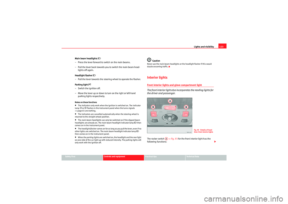
the driver and passenger.The rocker switch ⇒fig. 93 for the front interior light has the
following functions:
Fig. 93 Details of head-
liner: front interior lights
AA
Exeo_EN.book Seite 123 Freitag, 28. August 2009 10:14 10
Page 127 of 310
Lights and visibility125
Safety First
Controls and equipment
Practical tips
Technical Data
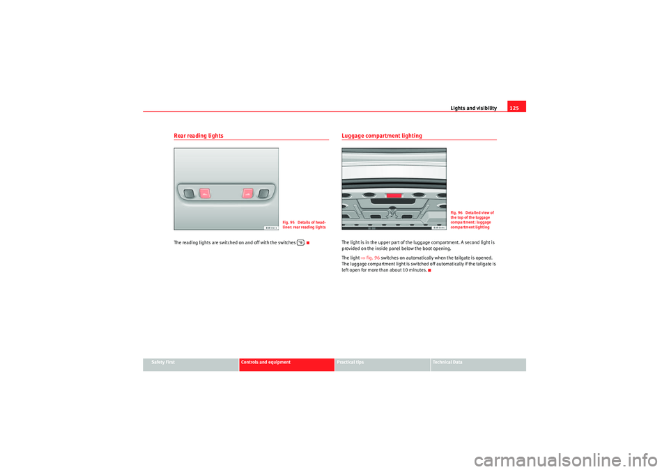
Rear reading lightsThe reading lights are switched on and off with the switches .
Luggage compartment lightingThe light is in the upper part of the luggage compartment. A second light is
provided on the inside panel below the boot opening.
The light ⇒fig. 96 switches on automatically when the tailgate is opened.
The luggage compartment light is switched off automatically if the tailgate is
left open for more than about 10 minutes.
Fig. 95 Details of head-
liner: rear reading lights
Fig. 96 Detailed view of
the top of the luggage
compartment: luggage
compartment lighting
Exeo_EN.book Seite 125 Freitag, 28. August 2009 10:14 10
Page 129 of 310
Lights and visibility127
Safety First
Controls and equipment
Practical tips
Technical Data
Sun blind*
Sun blinds are provided for the rear window and the rear side
windows.
Sun blinds (rear side windows)
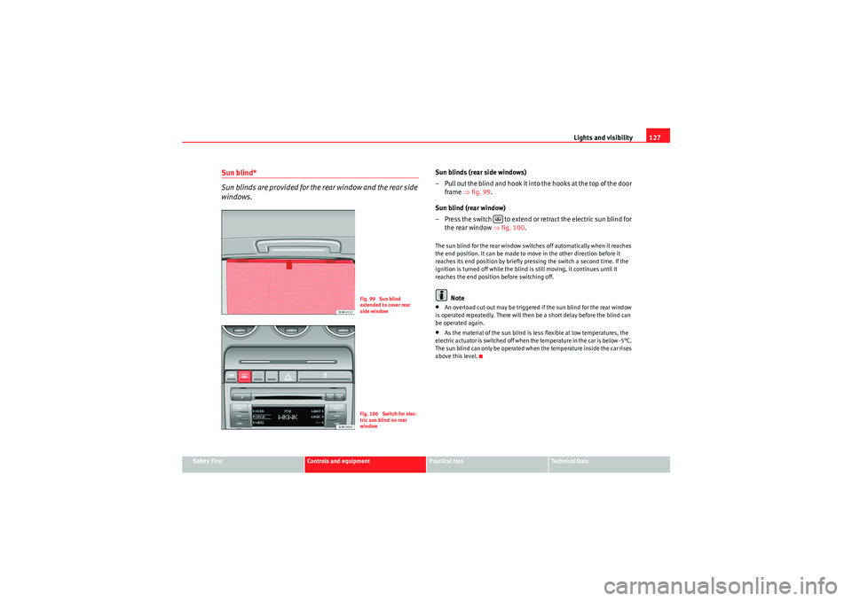
– Pull out the blind and hook it into the hooks at the top of the door
frame ⇒fig. 99 .
Sun blind (rear window)
– Press the switch to extend or retract the electric sun blind for the rear window ⇒fig. 100 .The sun blind for the rear window switches off automatically when it reaches
the end position. It can be made to move in the other direction before it
reaches its end position by briefly pressing the switch a second time. If the
ignition is turned off while the blind is still moving, it continues until it
reaches the end position before switching off.
Note
•An overload cut-out may be triggered if the sun blind for the rear window
is operated repeatedly. There will then be a short delay before the blind can
be operated again.•As the material of the sun blind is less flexible at low temperatures, the
electric actuator is switched off when the temperature in the car is below -5°C.
The sun blind can only be operated when the temperature inside the car rises
above this level.
Fig. 99 Sun blind
extended to cover rear
side windowFig. 100 Switch for elec-
tric sun blind on rear
window
Exeo_EN.book Seite 127 Freitag, 28. August 2009 10:14 10
Page 131 of 310
Lights and visibility129
Safety First
Controls and equipment
Practical tips
Technical Data
Rain sensor
The rain sensor* will only function in the intermittent wipe position. The inter-
mittent wipe function is enabled automatically when it starts to rain.
Before you reach a road speed of 6 km/h ,you will have to enable the rain
sensor manually by switching it off and back on again.
Use control to set the sensitivity of the rain sensor*.
If you have selected a high sensitivity level for the rain sensor the windscreen
wipers will react sooner to any moisture on the windscreen.
The wiper intervals in the intermittent wipe setting are also varied automati-
cally according to the road speed (in addition to the sensitivity setting).
WARNING
•For correct visibility and safe driving, the wiper must be in perfect
condition ⇒page 209. Failure to do so could result in an accident.•The rain sensor* is only intended to assist the driver. The driver is still
obliged to manually operate the windscreen wipers as required depending
on visibility.•Do not use water-repellent coatings on the windscreen. In bad visibility
conditions such as light rain, low sun or when driving at night, these coat-
ings can cause increased dazzle, which is a serious safety hazard. Such
coatings can also cause the wiper blades to judder.Caution
•In the event of frost, check that the wiper blade has not frozen before
enabling the windscreen wipers. Should the windscreen wiper system be
enabled when the blade is frozen, this could damage it or even the wind-
screen wiper system motor.•Make sure you switch off the windscreen wiper system (lever in position
0) before you use an automatic car wash. This will avoid inadvertent trig-
gering of the wipers and possible damage to the wiper system.
Note
•Check that the washer fluid reservoir is full before starting a long journey.
Fill the reservoir ⇒page 228.•Worn or dirty wiper blades can cause smearing on the glass which can
also impair the effectiveness of the rain sensor*. Check the condition of wind-
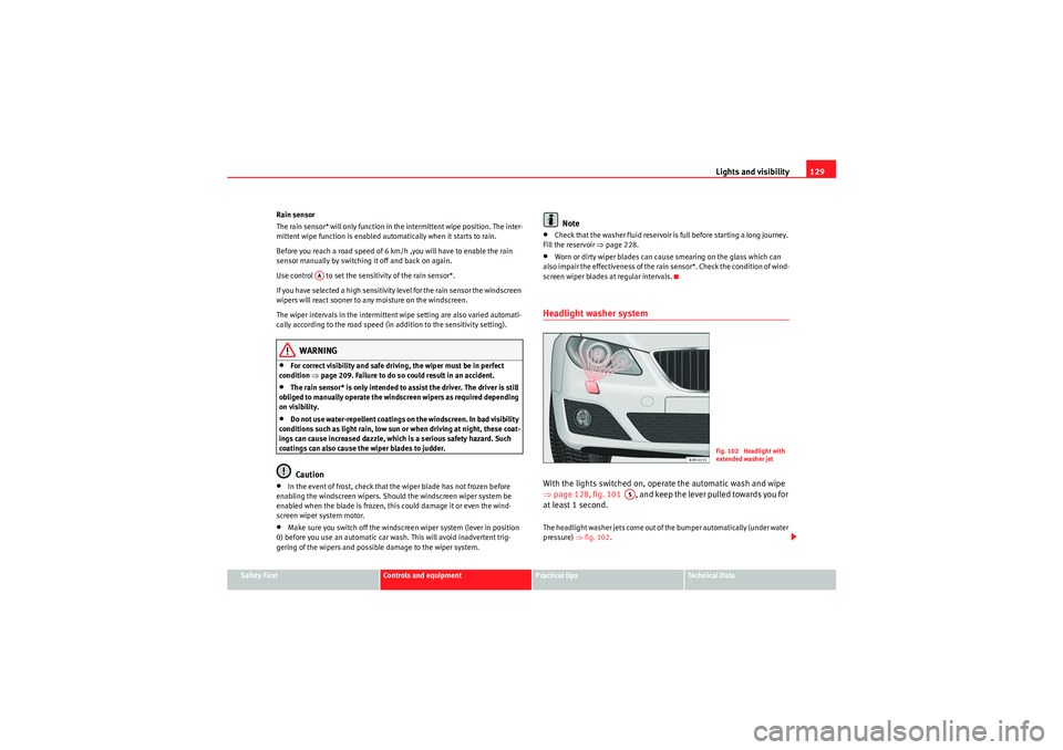
screen wiper blades at regular intervals.Headlight washer systemWith the lights switched on, operate the automatic wash and wipe
⇒ page 128, fig. 101 , and keep the lever pulled towards you for
at least 1 second.The headlight washer jets come out of the bumper automatically (under water
pressure) ⇒fig. 102 .
AA
Fig. 102 Headlight with
extended washer jet
A5
Exeo_EN.book Seite 129 Freitag, 28. August 2009 10:14 10
Page 133 of 310
Lights and visibility131
Safety First
Controls and equipment
Practical tips
Technical Data
•the interior lighting is switched on•reverse gear is engaged
Sensors for automatic headlights*
When the light switch is set to the AUTO position, the dipped beam head-
lights are switched on and off automatically according to the ambient light
level with the aid of the sensors located in the interior rear view mirror
⇒ page 116.WARNING
Electrolyte fluid can leak from a broken mirror. This fluid can cause irrita-
tion to the skin, eyes and respiratory organs. Wash thoroughly with clean
water should you come into contact with this fluid. Seek medical assist-
ance if needed!
Caution
Electrolyte fluid leaking from a broken mirror can cause damage to plastic
surfaces. Use a sponge or similar to remove the fluid as soon as possible.
Note
•The rear-view mirror's automatic anti-dazzle function* will only work prop-
erly if the sun blind* for the rear window is retracted and if there are no other
objects preventing light from reaching the interior mirror.•If you have to stick any type of sticker on the windscreen, do not do so in
front of the sensors. Doing so could prevent the automatic headlight or anti-
dazzle function from working correctly or even from working at all.
Exterior mirrors
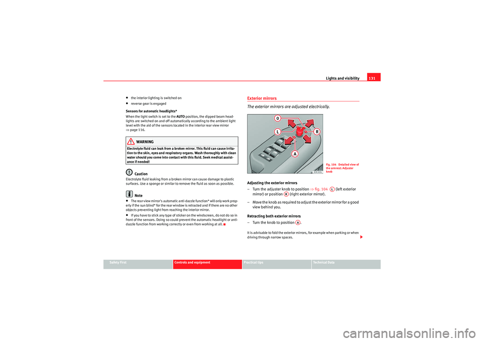
The exterior mirrors are adjusted electrically.Adjusting the exterior mirrors
– Turn the adjuster knob to position ⇒ fig. 104 (left exterior
mirror) or position (right exterior mirror).
– Move the knob as required to adjust the exterior mirror for a good view behind you.
Retracting both exterior mirrors
– Turn the knob to position .It is advisable to fold the exterior mirrors, for example when parking or when
driving through narrow spaces.
Fig. 104 Detailed view of
the armrest: Adjuster
knobAL
AR
AA
Exeo_EN.book Seite 131 Freitag, 28. August 2009 10:14 10
Page 135 of 310

Seats and stowage133
Safety First
Controls and equipment
Practical tips
Technical Data
Seats and stowageManual adjustment of the front seatsSeat adjuster controls
There are several seat adjustment functions for your conven-
ienceS o m e o f t h e e q u i p m e n t l i s t e d i s o nl y f i t t e d o n ce r ta i n m o d e l s o r i s a n o p t i o n a l
extra.
Control switches
Moving the seat backwards or forwards
Raising/lowering the seat
Adjusting the backrest angle
Adjusting lumbar support
Moving the seats forwards and backwards– Lift the lever ⇒fig. 105 and move the seat to the desired
position.
– Then release the lever and move the seat further until the catch engages.
WARNING
The driver's seat must only be moved forwards and backwards when the
vehicle is at a standstill. Failure to do so could result in an accident.Adjusting the seat height*Raising the seat
–Pull the lever ⇒ fig. 105 up repeatedly until the seat is in the
desired position.
Lowering the seat
– Press the lever down repeatedly until the seat is in the desired position.
WARNING
•The height of the driver's seat mu st not be adjusted while driving.
Failure to do so could result in an accident.
Fig. 105 Adjuster
controls on driver's seat
A1A2A3A4
A1
A1
A2A2
Exeo_EN.book Seite 133 Freitag, 28. August 2009 10:14 10
Page 137 of 310
Seats and stowage135
Safety First
Controls and equipment
Practical tips
Technical Data
Electric adjustment of front seats*Adjusting the seat
The arrangement of the switches corresponds with the design
of the seats.
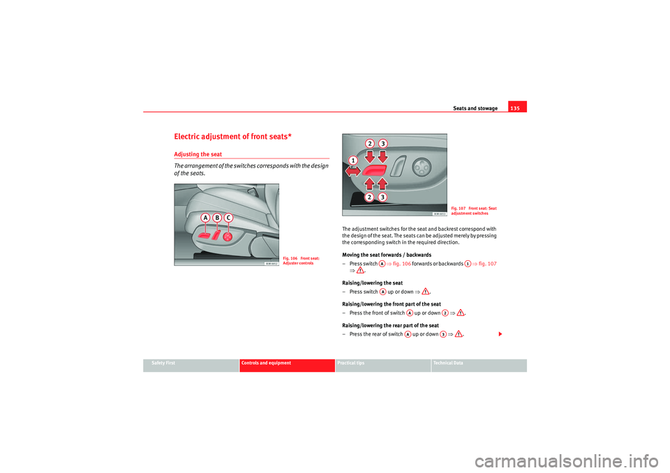
The adjustment switches for the seat and backrest correspond with
the design of the seat. The seats can be adjusted merely by pressing
the corresponding switch in the required direction.
Moving the seat forwards / backwards
–Press switch ⇒fig. 106 forwards or backwards ⇒fig. 107
⇒ .
Raising/lowering the seat
– Press switch up or down ⇒.
Raising/lowering the front part of the seat
– Press the front of switch up or down ⇒.
Raising/lowering the rear part of the seat
– Press the rear of switch up or down ⇒.
Fig. 106 Front seat:
Adjuster controls
Fig. 107 Front seat: Seat
adjustment switches
AA
A1
AA
AA
A2
AA
A3
Exeo_EN.book Seite 135 Freitag, 28. August 2009 10:14 10
Page 139 of 310

Seats and stowage137
Safety First
Controls and equipment
Practical tips
Technical Data
Adjusting the contour of lumbar support
– Press the front part of the adjuster switch ⇒page 136, fig. 109
to increase the contour of the lumbar support.
– Press the rear part of the adjuster switch to decrease the contour of the lumbar support.
Adjusting the height of lumbar support
– Press the top part of the adjuster switch to move the lumbar support upwards.
– Press the bottom part of the adjuster switch to move the lumbar support down.The lumbar support provides effective support for the natural curvature of the
spine to give a more relaxed seating position, especially on long journeys.
Memory for driver's seat*Description
The recall buttons in the driver's door can be used to store
and recall up to four different positions for the driver's seat
and exterior mirrors.Memory buttons
Using the recall buttons 1, 2, 3 and 4 ⇒fig. 110 , you can store and recall the
seat and exterior mirror positions for up to four different drivers.
button
The seat memory will be disabled if the button is in the up position
(press and release). The word
will light up next to the button (only
visible when the lights are switched on).
The stored settings will all remain in the memory. However, the seat and the
exterior mirrors can now only be adjusted using the conventional electrical
Fig. 110 Driver's door:
Memory system
STOP
STOP
STOP
Exeo_EN.book Seite 137 Freitag, 28. August 2009 10:14 10
Page 141 of 310
Seats and stowage139
Safety First
Controls and equipment
Practical tips
Technical Data
Assigning remote control keys
The key must be assigned to a memory button so that the
positions stored in the memory can also be recalled using the
remote control key.Assigning the remote control key to a memory button
– Using the memory button, recall the settings that are to be
programmed onto the key.
– Keeping the memory button pressed down, press the unlock button on the remote control key within 10 seconds.
– Wait for about 2 seconds before releasing the memory button.
Deleting assignment of the remote control key to the memory
button
– Press and hold the button and press the unlock button on the remote control key within 10 seconds.
– Wait for about 2 seconds before releasing the button.The previous settings are automatically cancelled when the keys are re-
assigned to different memory buttons.
Head restraintsFront head restraints
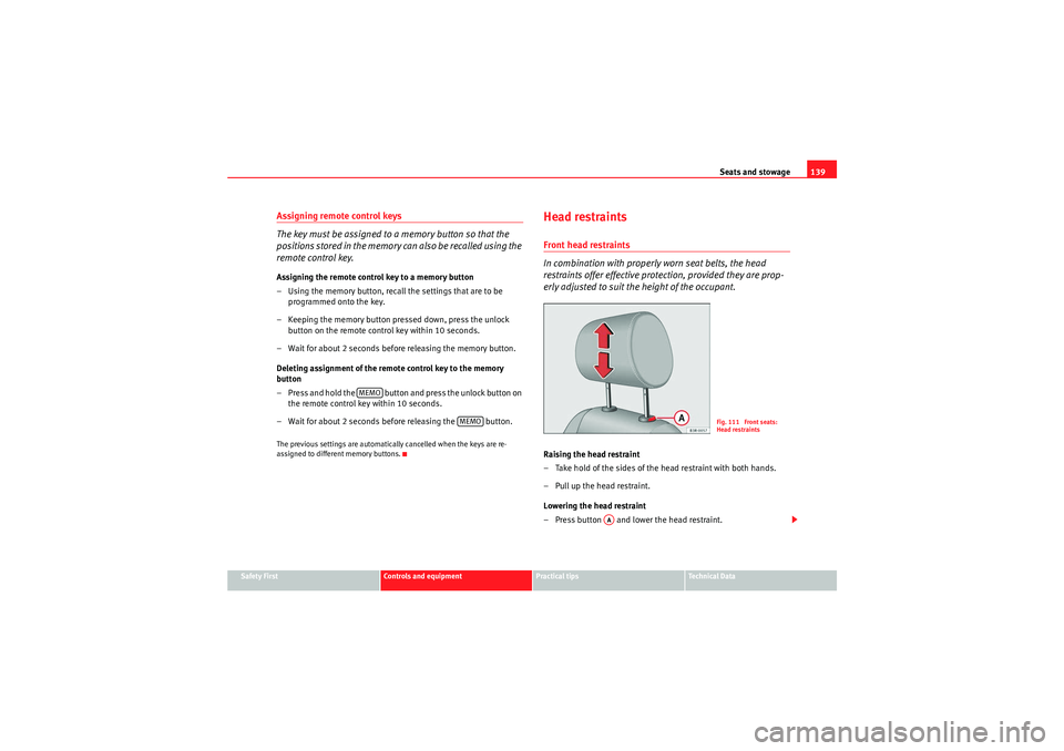
In combination with properly worn seat belts, the head
restraints offer effective protection, provided they are prop-
erly adjusted to suit the height of the occupant.Raising the head restraint
– Take hold of the sides of the head restraint with both hands.
– Pull up the head restraint.
Lowering the head restraint
– Press button and lower the head restraint.
MEMO
MEMO
Fig. 111 Front seats:
Head restraints
AA
Exeo_EN.book Seite 139 Freitag, 28. August 2009 10:14 10
Page 143 of 310
Seats and stowage141
Safety First
Controls and equipment
Practical tips
Technical Data
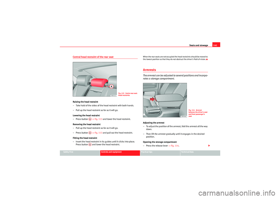
Central head restraint of the rear seatRaising the head restraint
– Take hold of the sides of the head restraint with both hands.
– Pull up the head restraint as far as it will go.
Lowering the head restraint
– Press button ⇒fig. 113 and lower the head restraint.
Removing the head restraint
– Pull up the head restraint as far as it will go.
– Press button ⇒fig. 113 and pull out the head restraint.
Fitting the head restraint
– Insert the head restraint in its gu ides until it clicks into place.
Press button and lower the head restraint.
When the rear seats are not occupied the head restraints should be moved to
the lowest position so that they do not obstruct the driver's field of vision.ArmrestsThe armrest can be adjusted to several positions and incorpo-
rates a storage compartment.Adjusting the armrest
– To adjust the position of the armrest, fold the armrest all the way down.
– Then lift the armrest gradually until it engages in the desired position.
Opening the storage compartment
– Press the release lever ⇒fig. 114 .
Fig. 113 Centre rear seat:
Head restraints
AAAAAA
Fig. 114 Armrest
between the driver's seat
and front passenger's
seat
Exeo_EN.book Seite 141 Freitag, 28. August 2009 10:14 10