technical specifications Seat Exeo 2011 Owners Manual
[x] Cancel search | Manufacturer: SEAT, Model Year: 2011, Model line: Exeo, Model: Seat Exeo 2011Pages: 313, PDF Size: 5.02 MB
Page 185 of 313

183
Driving
Back-up programme
A back-up system is in place if a fault should occur in the
control system.
The automatic gearbox switches to the back-up programme if a fault should
occur in the control system. This is indicated by a gear pinion symbol which
lights up on the instrument panel display.
It is still possible to move the selector lever to all positions. The manual
shift programme (tiptronic) is not available when the back-up programme is
active.
Vehicles with tiptronic gearbox: When the selector lever is in position D or S
or in the manual shift programme, the gearbox will remain in 3rd gear if 1st,
2nd or 3rd gears were engaged when the fault occurred. The gearbox will
remain in 5th gear if 4th, 5th or 6th gears were engaged. The gearbox will
then engage 3rd gear when you drive away from a standstill or after the en-
gine is restarted.
It will still be possible to use reverse gear in the normal way. However, the
electronic lock for reverse gear will be switched off.
CAUTION
Should the gearbox ever switch into the back-up programme, you should
take the vehicle to a technical service or qualified workshop as soon as pos-
sible. Steering wheel with paddle levers
The paddle levers on the steering wheel enable the driver to
manually select pre-programmed ratios or gears.
Fig. 148 Steering wheel:
tiptronic controls
– Briefly pull the left-hand paddle lever –
to change down to a
lower gear.
– Briefly pull the right-hand paddle lever +
to change up to a
higher gear.
The paddle levers are activated when the selector lever is in position D or S,
or the position for the manual shift programme (tiptronic).
The manual shift programme can, of course, still be operated using the gear
lever in the centre console.
Safety FirstOperating InstructionsPractical TipsTechnical Specifications
Page 187 of 313
185
Intelligent technology
If required, the ESP can also be enabled and disabled manually by briefly
pressing the ESP
button ⇒
fig. 149. The ESP warning lamp lights up when
the system is switched off, see ⇒ page 68.
In general, the ESP should be left switched on at all times. In particular cir-
cumstances where a certain amount of wheel slip is desirable, it may be ad-
visable to switch off the ESP. Examples:
● when driving with snow chains
● when driving in deep snow or on loose surfaces
● when rocking the vehicle backwards and forwards to free it.
The ESP should be switched on again afterwards as soon as possible.
WARNING
The ESP is not able to overcome the physical limits of adhesion. Even
with ESP, you should always adjust your speed to suit the conditions.
Please bear this in mind, especially on wet or slippery road surfaces. Do
not let the extra safety features tempt you into taking any risks when
driving. Failure to do so could result in an accident.
Anti-lock brake system (ABS)
ABS prevents the wheels from locking up under braking.
The anti-lock brake system (ABS) is an important part of the vehicle's active
safety system. However, the ABS will not necessarily guarantee shorter
stopping distances in all conditions. For instance, on loose gravel or fresh
snow on top of an icy surface (conditions which anyway require extreme
care and reduced speed), the stopping distance with ABS may even be
slightly longer. How the ABS works
The system runs an automatic self-check when the vehicle reaches a road
speed of about 6 km/h. This may be accompanied by a noise from the ABS
pump.
When one of the wheels is turning very slowly in relation to the road speed
and is close to locking up, the system will reduce the brake pressure on that
wheel. The driver is made aware of this adjustment process by a
vibration of
the brake pedal and an audible noise. This is a deliberate warning to the
driver that one or more of the wheels is tending to lock up and the ABS con-
trol function has intervened. In this situation it is important to keep the
brake pedal fully depressed so the ABS can regulate the brake application,
but do not “pump” the brake pedal.
WARNING
The grip provided by ABS is still subject to the physical limits of adhe-
sion. Always bear this in mind, especially on wet or slippery roads. If you
notice that the ABS is working (to counteract locked wheels under brak-
ing), you should reduce speed immediately to suit the road and traffic
conditions. Do not let the extra safety features tempt you into taking any
risks when driving. Failure to do so could result in an accident.
Note
If a malfunction should occur in the ABS, this is indicated by a warning lamp
⇒ page 67.
Safety FirstOperating InstructionsPractical TipsTechnical Specifications
Page 189 of 313

187
Intelligent technology
Note
If the ABS warning lamp lights up, this can also mean there is a fault in the
EDL. Take the vehicle to a specialised workshop as soon as possible.
Traction control system (TCS)
The traction control system prevents the drive wheels from
spinning when the vehicle is accelerating. General notes
The traction control system (TCS) is one of the functions incorporated in the
Electronic Stability Programme (ESP).
The traction control system (TCS) helps the vehicle to start moving, acceler-
ate or climb a gradient in slippery conditions where this may otherwise be
difficult or even impossible.
How it works
The TCS acts automatically, without the driver's intervention. With the aid of
the ABS sensors ⇒ page 185, the TCS monitors the speed of the drive
wheels. If the wheels start to spin, the engine speed is reduced automati-
cally to match the amount of grip available. The system is active across the
entire speed range.
The TCS works in conjunction with the ABS. If a malfunction occurs in the
ABS, the TCS will also be inoperative.
Note
To ensure that the TCS works properly, all four wheels must be fitted with
identical tyres. The difference in size of the wheels may lead to an unde-
sired reduction in engine power. Also see ⇒ page 241.
Safety FirstOperating InstructionsPractical TipsTechnical Specifications
Page 191 of 313
189
Intelligent technology
Note
If you wish to equip the vehicle with accessories such as a front spoiler or
wheel covers, it is important that the flow of air to the front wheels is not
obstructed, otherwise the brakes can overheat.
Brake servo
The brake servo assists the driver when braking
The brake servo increases the pressure you apply to the brake pedal. The
brake servo works only when the engine is running.
WARNING
Ensure the vehicle does not move while in neutral, when the engine is
stopped. Failure to do so could result in an accident.
Note
If the brake servo is not working, e.g. because the vehicle has to be towed
or because it is broken, you will have to press the brake pedal considerably
harder to make up for the lack of servo assistance.
Power steering
Power steering makes it easier to turn the steering wheel
when the engine is running. Power steering assists the driver by reducing the force needed to turn the
steering wheel. Power steering does not work if the engine is off. In this case the steering
wheel requires much more force to turn.
If the steering is held at its
turning limit when the vehicle is stationary, this
will place an excessive load on the power steering system. Turning the
steering wheel to its limit places a load on the system, which causes noise.
It will also reduce the idling speed of the engine.
CAUTION
When the engine is running, do not turn the steering wheel to its limit for
more than 15 seconds. Otherwise, there is a risk of damaging the power
steering.
Note
● If the power steering should fail at any time or the engine is switched off
(for instance when being towed), the vehicle can still be steered. However,
more effort will be required to turn the steering wheel.
● If the system is leaking or malfunctioning, please take the vehicle to a
specialised workshop as soon as possible.
● The power steering system requires a special hydraulic fluid. The fluid
reservoir is located at the front of the engine compartment on the left
⇒ page 290. The correct fluid level in the reservoir is important for the pow-
er steering to function properly. The hydraulic fluid level is checked at the
Inspection Service.
Servotronic*
The servotronic system electronically adjusts the power as-
sisted steering.
In vehicles equipped with servotronic power steering the degree of power
assistance ⇒ page 189 is adjusted
electronically according to road speed.
Safety FirstOperating InstructionsPractical TipsTechnical Specifications
Page 193 of 313
191
Driving and the environment
Driving and the environment
Running-in Running in a new engine
The engine needs to be run in over the first 1500 km.
Up to 1000 kilometres
– Do not drive at speeds of more than 2/3 the maximum speed.
– Do not accelerate hard.
– Avoid high engine revolutions.
– Do not tow a trailer.
From 1000 to 1500 kilometres
– Speeds can be gradually increased to the maximum road speed
or maximum permissible engine speed (rpm).
During its first few hours of running, the internal friction in the engine is
greater than later on, when all the moving parts have bedded in.
For the sake of the environment
If the engine is run in gently, its life will be increased and its oil consump-
tion reduced. Braking capacity and braking distance
The braking capacity and braking distance are influenced by
driving situations and road conditions.
The efficiency of the brakes depends directly on the
brake pad wear. The
rate of wear of the brake pads depends to a great extent on the conditions
under which the vehicle is operated and the way the vehicle is driven. If you
often drive in town traffic, drive short distances or have a sporty driving
style, we recommend that you have the thickness of your brake pads
checked by an Authorised Service Centre more frequently than recommen-
ded in the Service Plan.
If you drive with wet brakes, for example, after crossing areas of water, in
heavy rainfall or even after washing the vehicle, the effect of the brakes is
lessened as the brake discs are wet or even frozen (in winter). In this case
the brakes should be dried by pressing the brake pedal several times.
WARNING
Longer braking distances and faults in the brake system increase the risk
of accidents.
● New brake pads must be run in and do not have the correct friction
during the first 200 km. However, the reduced braking capacity may be
compensated by pressing on the brake pedal a little harder. This also ap-
plies when the brake pads have to be changed further on.
● If brakes are wet or frozen, or if you are driving on roads which have
been salted, braking power may be lower than normal.
Safety FirstOperating InstructionsPractical TipsTechnical Specifications
Page 195 of 313

193
Driving and the environment
Diesel engine particulate filter*
The diesel engine particulate filter eliminates soot produced
by burning diesel.
The diesel engine particulate filter eliminates most of the soot from the ex-
haust gas system. Under normal driving conditions, the filter cleans itself. If
the driving conditions do not allow the filter to clean itself (for example,
multiple short trips) the filter will be obstructed by dust and pollen and the
indicator for the diesel engine particulate filter indicator will light up.
This does not represent a fault, it is a warning that indicates that the filter
has not been able to regenerate automatically and that you must carry out a
cleaning cycle, as indicated in ⇒ page 80.
WARNING
● The diesel engine particulate filter may reach extremely high temper-
atures; the vehicle should be parked so that the exhaust pipe does not
come into contact with flammable materials underneath the vehicle. Oth-
erwise there is a risk of fire.
CAUTION
● Your vehicle is not designed to use biodiesel fuel. Never, under any cir-
cumstances refuel with biodiesel. The use of biodiesel fuel could damage
the engine and the fuel system. The addition of biodiesel to diesel by the
diesel producer in accordance with standard EN 590 is authorised and will
not cause damage to the engine or the fuel system.
● Using diesel fuel with a high sulphur content may significantly reduce
the working life of the diesel particulate filter. Your Authorised Service Cen-
tre will be able to tell you which countries have diesel with a high sulphur
content. Economical and environmentally friendly
driving
Economical and environmentally friendly driving
Fuel consumption, environmental pollution and wear to the engine, brakes
and tyres depends in large part on your driving style. By adopting an eco-
nomical driving style and anticipating the traffic situation ahead, you can
easily reduce fuel consumption by 10-15%. Some tips on how to help you
reduce pollution while saving money are listed below.
Drive anticipating the traffic situation
A vehicle uses most fuel when accelerating. When you anticipate the situa-
tion, you have to brake less often and, thus, accelerate less. If it is possible,
let the vehicle roll with a
gear engaged, for example, if you see a red light
ahead. The braking effect achieved in this way helps to reduce the wear of
brakes and tyres; emissions and fuel consumption are reduced to zero (dis-
connection due to inertia).
Change gear early to save energy
An effective way of saving fuel is to change up quickly through the gears.
Running the engine at high rpm in the lower gears uses an unnecessary
amount of fuel.
Manual gearbox: Change from first to second gear as quickly as possible.
We recommend that, whenever possible, you change to a higher gear upon
reaching 2000 rpm. Follow the “recommended gear” indication that ap-
pears on the instrument panel ⇒ page 73.
Avoid driving at high speed
We advise you not to drive at the top speed permitted by the vehicle. Fuel
consumption, exhaust emissions and noise levels all increase very rapidly
at higher speeds. Driving at moderate speeds will help to save fuel.
Safety FirstOperating InstructionsPractical TipsTechnical Specifications
Page 197 of 313

195
Driving and the environment
Environmental friendliness
Environmental protection is a top priority in the design, choice of materials
and production of your new Seat.
Design measures for economical recycling
● Joints and connections designed for easy dismantling
● Modular construction to facilitate dismantling
● Increased use of single-grade materials
● Plastic parts and elastomers are marked in accordance with ISO 1043,
ISO 11469 and ISO 1629
Choice of materials
● Nearly all materials used can be recycled
● Similar types of plastics grouped together for easy recycling
● Recycled materials used in manufacture
● Reduction of volatile compounds in plastics
● CFC-free refrigerant in air conditioner
Compliance with prohibited materials regulation : cadmium, lead, mercury,
chrome VI.
Manufacturing methods
● Use of recycled material for manufacturing plastic parts
● Solvent-free cavity sealing
● Solvent-free wax for protecting the vehicles in transit
● Solvent-free adhesives
● No CFCs used in production
● Surplus materials used extensively for energy conversion and building
materials
● Overall water consumption reduced
● Heat recovery systems
● The use of water-soluble paints Driving abroad
Observations
To drive abroad, the following must be taken into consideration:
● For vehicles fitted with a catalytic converter ensure that unleaded petrol
is available for the journey. See the chapter “Refuelling”. Automobile organ-
isations will have information about service station networks selling unlea-
ded fuel.
● In some countries, it is possible that your vehicle model is not sold, and
therefore spare parts are not available or the Authorised Services can only
carry out limited repairs.
SEAT importers and distributors will gladly provide information about the
technical preparations that you vehicle requires and also about necessary
maintenance and repair possibilities.
Adhesive strips for headlights
If you have to drive a right-hand drive vehicle in a left-hand drive country, or
vice versa, the asymmetric dipped beam headlights will dazzle oncoming
traffic.
To prevent dazzling, you must apply stickers to certain parts of the head-
light lenses. Further information is available at your Authorised Service Cen-
tre.
In vehicles with adaptive headlights, the rotation system must previously be
disconnected. To do this, please go to a specialised workshop.
Safety FirstOperating InstructionsPractical TipsTechnical Specifications
Page 199 of 313
197
Trailer towing
Where possible, operate the trailer with the maximum permitted drawbar
load on the ball joint of the towing bracket, but do not exceed the specified
limit.
Tyre pressure
Check the tyre pressures on your vehicle, and adjust for “full load” condi-
tions (refer to the sticker listing the tyre pressures on the door pillar). It may
also be necessary to adjust the tyre pressures on the trailer according to the
recommendations of the trailer manufacturer.
Exterior mirrors
Check whether you can see enough of the road behind the trailer with the
standard mirrors. If this is not the case you should have additional mirrors
fitted. The two exterior mirrors should be fitted on folding arms. Adjust the
mirrors to give sufficient rear vision.
Headlights
Before starting a journey, check the headlight beam settings with the trailer
hitched up. If necessary, alter the height of the headlight beams by means
of the headlight range control. See ⇒ page 119.
Power supply
When you remove the ignition key, the power supply to the trailer is inter-
rupted.
Removable ball joint coupling
Vehicles with a factory-fitted towing bracket are equipped with a removable
ball joint coupling. This is stored in the spare wheel well in the luggage
compartment together with the necessary fitting instructions.
Note
If you frequently tow, we recommend you also have the vehicle serviced be-
tween services. Notes on towing
Towing a trailer involves additional attention by the driver.
Weight distribution
The weight distribution of a loaded trailer with an unladen vehicle is very
unfavourable. However, if this cannot be avoided, drive extra slow to allow
for the unbalanced weight distribution.
Speed
The stability of the vehicle and trailer is reduced with increasing speed.
Therefore, it is advisable not to drive at the maximum permissible speed in
unfavourable road, weather or wind conditions. This especially applies
when driving downhill.
You should always reduce speed immediately if the trailer shows the slight-
est sign of swaying. Never try to stabilise the trailer by accelerating.
Anticipate hazards and brake in good time. If towing a trailer with an inertia
brake, first brake gently and then harder. This will prevent brake tapping by
the trailer wheels when they lock. Select a low gear in due course before go-
ing down a steep downhill. This enables you to use the engine braking to
slow down the vehicle.
Swaying and pitching can be reduced by stabiliser aids. We recommend
having stabiliser aids installed when towing trailers with a high trailer
weight. They can be purchased and installed at a Technical Service.
Reheating
When climbing long hills in hot weather with the engine running fast in low
gear, you should keep an eye on the coolant temperature gauge ⇒ page 60.
Reduce speed immediately if the needle moves to the right end of the scale.
If the temperature warning lamp in the instrument panel should start
flashing, stop the vehicle and let the engine cool down by running it at
idling speed for a few minutes.
Safety FirstOperating InstructionsPractical TipsTechnical Specifications
Page 201 of 313
199
Trailer towing
Removable towing bracket Introduction
Special care is required when fitting and removing the tow-
ing bracket.
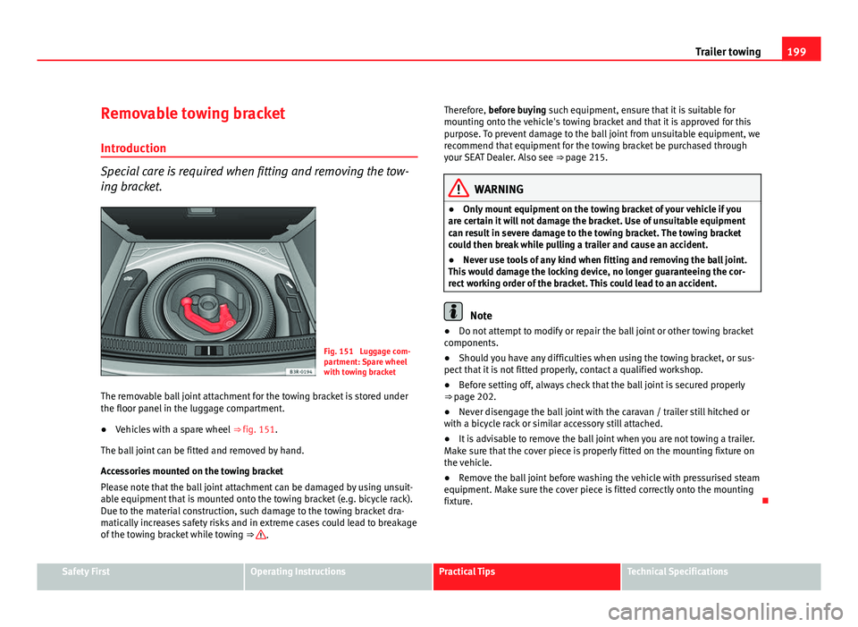
Fig. 151 Luggage com-
partment: Spare wheel
with towing bracket
The removable ball joint attachment for the towing bracket is stored under
the floor panel in the luggage compartment.
● Vehicles with a spare wheel ⇒ fig. 151.
The ball joint can be fitted and removed by hand.
Accessories mounted on the towing bracket
Please note that the ball joint attachment can be damaged by using unsuit-
able equipment that is mounted onto the towing bracket (e.g. bicycle rack).
Due to the material construction, such damage to the towing bracket dra-
matically increases safety risks and in extreme cases could lead to breakage
of the towing bracket while towing ⇒
. Therefore, before buying such equipment, ensure that it is suitable for
mounting onto the vehicle's towing bracket and that it is approved for this
purpose. To prevent damage to the ball joint from unsuitable equipment, we
recommend that equipment for the towing bracket be purchased through
your SEAT Dealer. Also see
⇒ page 215.
WARNING
● Only mount equipment on the towing bracket of your vehicle if you
are certain it will not damage the bracket. Use of unsuitable equipment
can result in severe damage to the towing bracket. The towing bracket
could then break while pulling a trailer and cause an accident.
● Never use tools of any kind when fitting and removing the ball joint.
This would damage the locking device, no longer guaranteeing the cor-
rect working order of the bracket. This could lead to an accident.
Note
● Do not attempt to modify or repair the ball joint or other towing bracket
components.
● Should you have any difficulties when using the towing bracket, or sus-
pect that it is not fitted properly, contact a qualified workshop.
● Before setting off, always check that the ball joint is secured properly
⇒ page 202.
● Never disengage the ball joint with the caravan / trailer still hitched or
with a bicycle rack or similar accessory still attached.
● It is advisable to remove the ball joint when you are not towing a trailer.
Make sure that the cover piece is properly fitted on the mounting fixture on
the vehicle.
● Remove the ball joint before washing the vehicle with pressurised steam
equipment. Make sure the cover piece is fitted correctly onto the mounting
fixture.
Safety FirstOperating InstructionsPractical TipsTechnical Specifications
Page 203 of 313
201
Trailer towing
Make sure the ball joint is clean and undamaged
– Check the locking pin A
, release pin B, shaft section C and
knob D ⇒ fig. 153 on the ball joint to make sure they are clean
and undamaged.
The spring mechanism inside the ball joint must be in the ready
position
– Check that the red marking A
⇒ fig. 154 on the knob is inside
the black zone marked on the ball joint.
– Check that the locking pin B
is inside the holes in the shaft
section of the ball joint.
– Check that the knob protrudes visibly from the ball joint, so that
there is a clear gap C
between the knob and the ball joint.
The ball joint can only be installed if the internal spring mechanism is in the
ready position.
Cont ⇒ page 201, Fitting the ball joint (step 3). Fitting the ball joint (step 3)
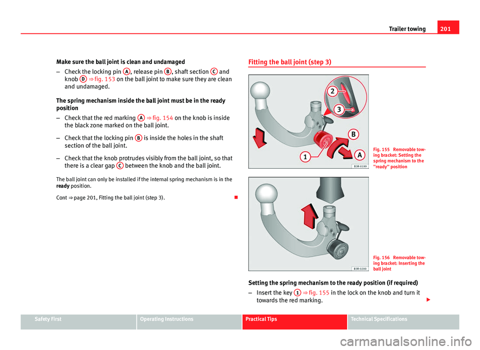
Fig. 155 Removable tow-
ing bracket: Setting the
spring mechanism to the
"ready" position
Fig. 156 Removable tow-
ing bracket: Inserting the
ball joint
Setting the spring mechanism to the ready position (if required)
– Insert the key 1
⇒ fig. 155 in the lock on the knob and turn it
towards the red marking.
Safety FirstOperating InstructionsPractical TipsTechnical Specifications