technical specifications Seat Exeo 2011 Manual PDF
[x] Cancel search | Manufacturer: SEAT, Model Year: 2011, Model line: Exeo, Model: Seat Exeo 2011Pages: 313, PDF Size: 5.02 MB
Page 145 of 313
143
Seats and storage compartments
Extending the luggage compartment
The two sections of the backrest can be folded forwards ei-
ther together or separately to increase the capacity of the
luggage compartment.
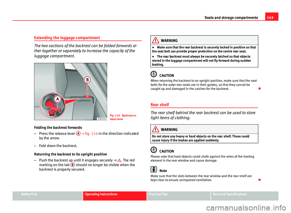
Fig. 116 Backrest re-
lease lever
Folding the backrest forwards
– Press the release lever A
⇒ fig. 116 in the direction indicated
by the arrow.
– Fold down the backrest.
Returning the backrest to its upright position
– Push the backrest up until it engages securely ⇒
. The red
marking on the tab B should no longer be visible when the
backrest is properly secured.
WARNING
● Make sure that the rear backrest is securely locked in position so that
the seat belt can provide proper protection on the centre rear seat.
● The rear backrest must always be securely latched so that objects
stored in the luggage compartment will not fly forward during sudden
braking.
CAUTION
When returning the backrest to an upright position, make sure that the seat
belts for the outer rear seats are in their guides, so that they cannot be
caught up and damaged in the catches for the backrest.
Rear shelf
The rear shelf behind the rear backrest can be used to store
light items of clothing.
WARNING
Do not store any heavy or hard objects on the rear shelf. These could
cause injury if the brakes are applied suddenly.
CAUTION
Please note that hard objects could chafe against the wires of the heating
element in the rear window and cause damage.
Note
Make sure that the slots between the rear window and the rear shelf are
kept clear to ensure unimpaired ventilation.
Safety FirstOperating InstructionsPractical TipsTechnical Specifications
Page 147 of 313
145
Seats and storage compartments
Note
Do not fold away the ski bag after use if it is still damp.
Roof rack
Description
Additional luggage can be carried on the roof rack. Note the following points if you intend to carry loads on the roof:
● There are aerodynamic drainage channels on the roof of the vehicle and,
therefore, normal roof racks cannot be used. We recommend using the ba-
sic support units from the range of genuine SEAT accessories.
● These basic supports are the base of a complete roof rack system. For
safety reasons, however, the corresponding additional fastenings must be
fitted to carry luggage, bicycles, surfboards, skis and boats. All the parts of
this system are available from SEAT Authorised Services.
CAUTION
Any damage to the vehicle caused by the use of other types of roof rack or
incorrect installation will not be covered by the factory warranty. The roof
rack system must therefore be installed exactly according to the instructions
provided. Attachment points
The roof rack must be attached at the marked points only.
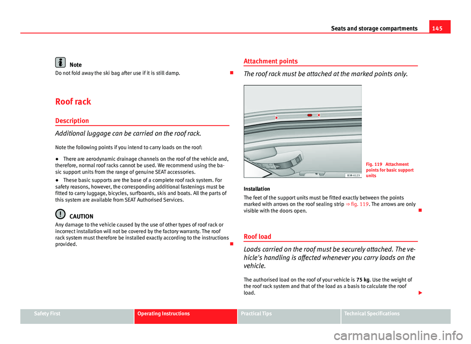
Fig. 119 Attachment
points for basic support
units
Installation
The feet of the support units must be fitted exactly between the points
marked with arrows on the roof sealing strip ⇒ fig. 119. The arrows are only
visible with the doors open.
Roof load
Loads carried on the roof must be securely attached. The ve-
hicle's handling is affected whenever you carry loads on the
vehicle. The authorised load on the roof of your vehicle is 75 kg. Use the weight of
the roof rack system and that of the load as a basis to calculate the roof
load.
Safety FirstOperating InstructionsPractical TipsTechnical Specifications
Page 149 of 313

147
Seats and storage compartments
Drink holder in the rear armrest*
Fig. 121 Drink holder in
the rear armrest
Opening the drink holder
– Press the symbol A
⇒ fig. 121.
Adjusting the retainer arm
– To adjust one of the retainer arms B
, release it by pressing in
the direction indicated (arrow) and move it as required.
The retainer arm should be positioned against the drink holder so that it is
held securely.
One or two drink holders can be held in the centre console.
WARNING
● Do not put any hot drinks in the drink holder while the vehicle is mov-
ing. You can be scalded if the hot liquid is spilt.
● Do not use hard china cups or glasses. These could cause injury in the
event of an accident.
Ashtray*, cigarette lighter* and electric
sockets* Front ashtray*
Fig. 122 Centre console:
Open ashtray
Opening the ashtray
– Lightly press the front part of the ashtray A
⇒ fig. 122.
Safety FirstOperating InstructionsPractical TipsTechnical Specifications
Page 151 of 313

149
Seats and storage compartments
Using the cigarette lighter
– Press in the cigarette lighter button.
– Wait for the lighter to pop out slightly.
– Pull out the cigarette lighter immediately.
– Use the glowing heater element of the cigarette lighter to light
your cigarette.
– Put the cigarette lighter back in its socket.
Operating the socket
– Take out the cigarette lighter.
– Insert the plug of the electrical appliance into the cigarette
lighter socket.
The cigarette lighter ⇒ fig. 124 employs a standard 12 volt socket, which can also be used as a power source for electrical appliances. The applian-
ces connected to the socket must not exceed a power rating of 100 W.
WARNING
● Be careful when using the electric cigarette lighter. Carelessness or
negligence when using the cigarette lighter can cause burns.
● The lighter will only work when the ignition is switched on.
● The electrical sockets and, therefore, any appliances connected to
them will only work when the ignition is switched on.
CAUTION
Always use the correct type of plugs to avoid damaging the sockets.
Note
The use of electrical appliances with the engine switched off will cause a
battery discharge.
Power socket*
Electrical equipment can be connected to the 12 volt socket.
Fig. 125 Detailed view of
the side trim in the lug-
gage compartment: 12
volt socket
– Lift the power socket cover ⇒ fig. 125.
– Insert the plug of the electrical appliance into the socket.
Electrical equipment can be connected to the 12 volt socket. The appliances
connected to the socket must not exceed a power rating of 100 W.
Safety FirstOperating InstructionsPractical TipsTechnical Specifications
Page 153 of 313

151
Seats and storage compartments
WARNING
● Heavy appliances or connectors (for example, adapters) which hang
down directly from the Europlug socket may damage the socket with the
resultant risk of injury.
● Ensure that appliances connected to the socket are secure to prevent
them from being thrown around the vehicle in the event of sharp braking
or an accident. This could result in severe injury or loss of life ⇒ page 16,
Storing objects.
● Never spill liquid over the socket – there is a risk of death. If any
moisture enters the socket, ensure that it is thoroughly dry before using.
● Improper use of the sockets or electrical accessories can lead to seri-
ous injuries or cause a fire, with the resultant risk of injury.
● Children must never be left alone in the vehicle with the engine run-
ning. They could cause an accident.
● Appliances connected to the socket do not behave in the same way as
when they are connected to the mains power supply. They may overheat
during use and cause injury.
● When using adapters and extension leads, the childproof safety de-
vice on the 230 volt socket is disconnected and the socket is live. Risk of
injury!.
● Never insert objects which conduct electricity, such as a needle, in
the pins of the 230 volt socket. There is a risk of death.
● Always switch off electrical appliances connected to the socket if the
inverter goes off as a result of overheating. Failure to comply could result
in injuries.
CAUTION
● The instructions for handling appliances connected to the socket must
be observed.
● If the power consumption of the appliances connected exceeds 150
watts, the socket inverter will overheat. If the temperature exceeds a certain
value, the inverter will switch off. It may also switch off if the outside tem- perature is very high, even if the power consumption is normal. The inverter
will switch on again automatically after it has cooled down. Appliances con-
nected to the socket, and which have been left switched on, will automati-
cally come back on
⇒
.
● Do not connect neon lamps to the socket. For technical reasons, these
could break down.
● Do not connect 115 volt appliances to the 230 volt power socket, as
they could be damaged. If you have any queries, please check the manufac-
turer's label for details of the power supply accepted by the appliance.
● With some adapters, for example for laptops, their built-in overload dis-
connection system prevents the equipment from switching on in the event
of an excessive start-up current. In this case, disconnect the adapter from
the power supply and try to reconnect after ten seconds.
Note
● Non-insulated equipment may cause interference to the radio or vehicle
electronics.
● The Europlug socket has a built-in childproof device and only carries live
current when the Europlug is correctly plugged in.
● Some appliances may not operate correctly in the absence of adequate
power (watts).
● In some countries this socket is 115 volts. Therefore the socket should
have a different inverter installed at the factory. You can obtain retrofit kits
from your Authorised Technical Service. Do not connect 115 Volt appliances
to the 230 Volt socket.
● The use of electrical equipment in the vicinity of the aerial in the rear
window may cause interference to the reception of stations broadcasting in
AM.
Safety FirstOperating InstructionsPractical TipsTechnical Specifications
Page 155 of 313

153
Seats and storage compartments
Compartments in the door trim
Storage compartments are provided in the door trims.
Fig. 128 Door trim with
storage compartment
WARNING
The storage compartments in the door trims should only be used to store
small objects. Make sure that they are stored safely inside the compart-
ment, as they might otherwise impair the protection offered by the side
airbags.
Coat hooks
There is a coat hook above each of the rear doors.
Fig. 129 Area above the
rear doors: Coat hooks
WARNING
● Please make sure that any items of clothing hanging from the coat
hooks do not obstruct your view to the rear.
● The coat hooks should only be used for lightweight clothing. Do not
leave any heavy or sharp objects in the pockets.
● Do not use clothes hangers to hang up the clothing, as this could in-
terfere with the function of the head-protection airbags*.
Safety FirstOperating InstructionsPractical TipsTechnical Specifications
Page 157 of 313
155
Air conditioning
Air conditioning 2C-Climatronic
Description
The air conditioner is designed to automatically keep the
passenger compartment at the temperature you find most
comfortable at all times of the year. Recommended settings:
– Set the temperature to 22 °C (71 °F).
– Press the AUTO
⇒ fig. 130 button.
The following setting quickly provides a comfortable temperature inside the
vehicle. We therefore recommend you do not modify the setting unless you
find this temperature uncomfortable or where circumstances require as
such.
The air conditioner provides heating and ventilation and also cools and de-
humidifies the air inside the vehicle.
The air conditioner is fully automatic and will constantly maintain the tem-
perature which has been set. To achieve this, the temperature of the air sup-
plied to the interior, the blower speed (volume of air delivery) and the air
distribution are regulated automatically. The system also takes solar radia-
tion into account and, therefore, no subsequent manual readjustments are
required. Therefore, automatic mode ⇒ page 158 should be used for the
comfort of all the passengers in virtually all conditions throughout the year.
Please note the following points: The humidity of the air is automatically reduced when the system cools the
interior of the vehicle. This helps to prevent condensation on the windows.
If the humidity and temperature outside the vehicle are high,
condensation
can drip off the evaporator in the air cooling system and form a pool under-
neath the vehicle. This is normal and does not indicate a leak.
If the outside temperature is low, the blower normally only switches to a
higher speed once the coolant has warmed up sufficiently (this does not ap-
ply to the defrost setting).
In order to achieve maximum engine power, the air conditioner compressor
is temporarily switched off when pulling away from standstill with full throt-
tle.
The compressor also switches off if the coolant temperature is excessively
high to ensure adequate engine cooling under extreme loads.
Pollution filter
The pollution filter (a combined particulate filter and activated charcoal fil-
ter) serves as a barrier against impurities in the outside air, including dust
and pollen.
For the air conditioner to work with maximum efficiency, the pollution filter
element must be replaced at the intervals specified in the Service Plan.
If the vehicle is driven in areas with a high level of air pollution and the filter
is no longer fully effective, it may be necessary to change the filter element
more frequently.
Safety FirstOperating InstructionsPractical TipsTechnical Specifications
Page 159 of 313
157
Air conditioning
Controls
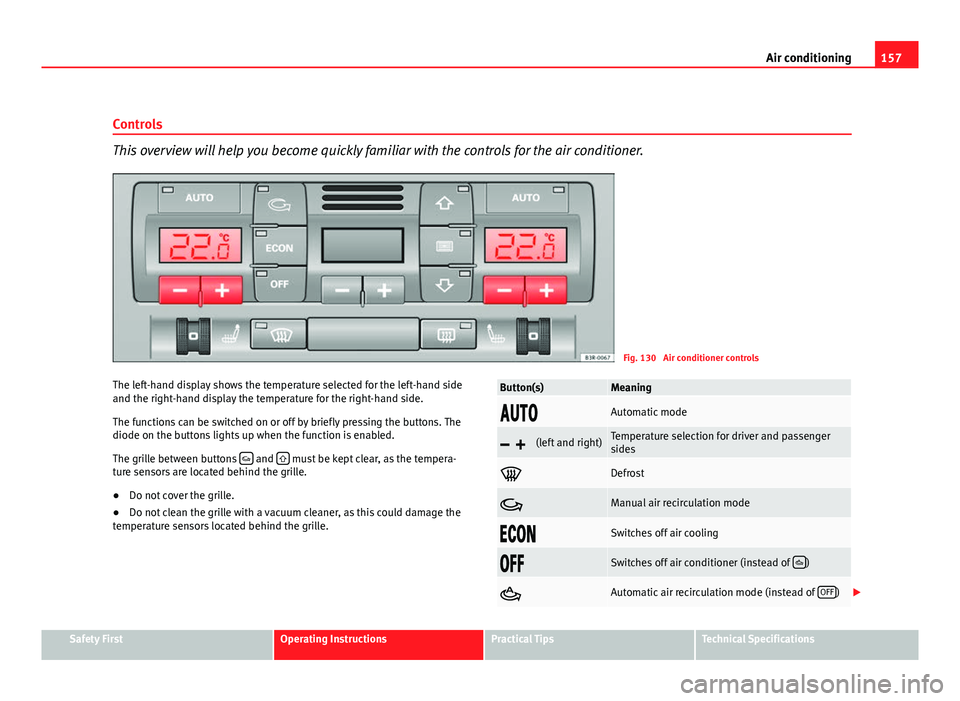
This overview will help you become quickly familiar with the controls for the air conditioner.
Fig. 130 Air conditioner controls
The left-hand display shows the temperature selected for the left-hand side
and the right-hand display the temperature for the right-hand side.
The functions can be switched on or off by briefly pressing the buttons. The
diode on the buttons lights up when the function is enabled.
The grille between buttons
and must be kept clear, as the tempera-
ture sensors are located behind the grille.
● Do not cover the grille.
● Do not clean the grille with a vacuum cleaner, as this could damage the
temperature sensors located behind the grille.
Button(s)Meaning
Automatic mode
(left and right)Temperature selection for driver and passenger
sides
Defrost
Manual air recirculation mode
Switches off air cooling
Switches off air conditioner (instead of )
Automatic air recirculation mode (instead of OFF)
Safety FirstOperating InstructionsPractical TipsTechnical Specifications
Page 161 of 313

159
Air conditioning
Defrosting
The windscreen and side windows are defrosted or demisted
as quickly as possible.
– To enable this mode, press the
⇒
fig. 130 button.
– To switch off, press the
button again, or select the AUTO but-
ton.
The temperature is regulated automatically. The air output is increased to
maximum and most of the air comes out of outlets 1 and 2 ⇒ page 162.
The air recirculation and ECON modes are switched off when the
button
is pressed.
Air recirculation: manual activation
The air recirculation setting prevents fumes etc. from enter-
ing the interior.
Activating air recirculation mode
– Press button
⇒ fig. 130 ⇒ .
Deactivating air recirculation mode
– Press the
button again or
– Press the AUTO
button or
– Press button
.
In this setting, the air in the vehicle is constantly recirculated. We recom-
mend using the air recirculation mode in the following circumstances: ●
When driving through a tunnel or in traffic congestions, to prevent ex-
haust gas entering the interior of the vehicle.
WARNING
Do not drive for too long with the air recirculation mode enabled because,
if the compressor is disconnected, the windscreen may mist up because
no fresh air is entering the interior of the vehicle, with the subsequent
risk of accidents.
ECON Mode (economy) ECON
ECON mode helps save fuel.
– To activate, press the ECON
button ⇒ fig. 130.
– To deactivate, press the ECON
button again or select the AUTObutton.
Air cooling is disconnected in ECON mode. The heating and the blower are
adjusted automatically. “ECON” stands for “Economy”. Disconnecting air
cooling (compressor) reduces fuel consumption.
Please note that the interior temperature must not be lower than the outside
temperature in ECON mode. The blower does not cool or dehumidify the air
in the interior. The windows could therefore mist up.
In diesel vehicles, the auxiliary heater is switched off in ECON mode to save
fuel.
Safety FirstOperating InstructionsPractical TipsTechnical Specifications
Page 163 of 313
161
Air conditioning
Switching the temperature display from °C to °F and vice
versa
The temperature display can be switched from °C (degrees
Celsius) to °F (degrees Fahrenheit) and vice versa. – Press and hold the
button for air recirculation mode and
briefly press the plus button of the left-hand temperature selec-
tor ⇒ fig. 130.
Switching the air conditioner on/off
Switching the air conditioner off: models with an OFF button
– Press the OFF
button. The air conditioner is switched off and
the supply of air from outside the vehicle is cut off.
Switching the air conditioner off: models with a
button
– Keep pressing the -
button for the blower until the display seg-
ment is empty. The air conditioner is switched off and the sup-
ply of air from outside the vehicle is cut off.
Switching the air conditioner on: models with an OFF
button
– Press the OFF
button again, or
– Press the AUTO
button or
– Press one of the air distribution buttons
, or .
Switching the air conditioner on: models with a
button
– Press the +
button for the blower, or –
Press the AUTO
button or
– Press one of the air distribution buttons
, or .
The air conditioner also starts to operate if one of the blower or temperature
selector buttons is pressed.
Blower speed -
+
The automatically selected blower speed can be reduced or
increased manually.
– Press the -
and + buttons in the centre of the control panel
⇒ fig. 130 to set the blower to the desired speed (and regulate
the volume of air delivery).
The air conditioner system automatically regulates the blower speed accord-
ing to the interior temperature. However, you can also adjust the air delivery
manually. The current blower setting is illustrated by a bar in the middle dis-
play (above the buttons).
Automatic change of passenger temperature
In order to automatically set the passenger temperature like the driver tem-
perature, press the AUTO button on the driver side for 2 seconds approxi-
mately. In order to automatically set the driver temperature like the passen-
ger temperature, press the AUTO
button on the passenger side for 2 sec-
onds approximately.
Safety FirstOperating InstructionsPractical TipsTechnical Specifications