esp Seat Ibiza 2017 Edition 11.17 Owner's Guide
[x] Cancel search | Manufacturer: SEAT, Model Year: 2017, Model line: Ibiza, Model: Seat Ibiza 2017Pages: 312, PDF Size: 6.51 MB
Page 94 of 312
Safety
Transporting children safely Chi l
d s
afety
Introduction For safety reasons, as we have learned from
acc
ident
statistics, we recommend that chil-
dren under 12 years of age travel in the rear
seats. Depending on their age, height and
weight, children travelling in rear seats must
use a child seat or a seat belt. For safety rea-
sons, the child seat should be installed in the
rear seat, behind the front passenger seat or
in the centre back seat.
The physical laws involved and the forces
acting in a collision apply also to children
››› page 83. But unlike adults, children do not
have fully developed muscle and bone struc-
tures. This means that children are subject to
a greater risk of injury.
To reduce the risk of injuries, children must
always use special child restraint systems
when travelling in the vehicle.
We recommend the use of child safety prod-
ucts from the SEAT Original Accessories Pro-
gramme, which includes systems for all ages
made by “Peke” (not for all countries) (see
www.seat.com). These systems have been especially de-
signed and ap
pr
oved, complying with the
ECE-R44. regulation.
SEAT recommends securing the child seats
shown on the website as described below:
● Child seats in the opposite direction of
travel
(group 0+): ISOFIX and support bracket
(Peke G0 Plus + ISOFIX Base (RWF)).
● Child seats in the direction of travel (group
1): ISOFIX and T
op Tether (Peke G1 ISOFIX
DUO Plus).
● Child seats in the direction of travel (group
2): seat belt
and ISOFIX (RÖMER KIDFIX XP ©
).
● Child seats in the direction of travel (group
3): with seat
belt (TAKATA MAXI PLUS ©
).
Follow the manufacturer's instructions and
observe any statutory requirements when in-
stalling and using child seats. Always read
and note ››› page 92.
We recommend you always carry the manu-
facturer's Child Seat Instruction Manual to-
gether with the on-board documentation.
Important information regarding the
front p
assenger's airbag Read the additional information carefully
› ›
›
page 24. Read and always observe the safety informa-
tion included in the fo
llowing chapters:
● Safety distance with respect to the passen-
ger airbag ›
›› page 86.
● Objects between the passenger and the
pas
senger side airbag ››› in Front airbags
on p ag
e 88
.
The passenger side front airbag, when ena-
bled, is a serious risk for a child that is facing
backward since the airbag can strike the seat
with such force that it can cause serious or
fatal injuries. Children up to 12 years old
should always travel on the rear seat.
Therefore we strongly recommend you to
transport children on the rear seats. This is
the safest location in the vehicle. Alternative-
ly, the front passenger airbag can be disa-
bled with a key-operated switch ››› page 90.
When transporting children, use a child seat
suitable for the age and size of each child
››› page 94. WARNING
● If a c hi
ld seat is secured to the front pas-
senger seat, the risk to the child of sustain-
ing critical or fatal injuries in the event of an
accident increases.
● An inflating front passenger airbag can
strike the r
ear-facing child seat and project it
with great force against the door, the roof or
the backrest. 92
Page 95 of 312
Transporting children safely
●
Never in s
tall a child seat facing backwards
on the front passenger seat unless the front
passenger front airbag has been disabled.
Risk of potentially fatal injuries to the child!
However, if it is necessary, in exceptional ca-
ses, to transport a child in the front passen-
ger seat, the front passenger front airbag
must always be disabled ››› page 90, Activa-
tion and deactivation of front passenger air-
bag*. If the passenger seat has a height ad-
justment option, move it to the highest, most
upright position. If it is a fixed seat, it should
be moved to the rearmost position possible.
● For those vehicles that do not include a key
lock sw
itch to deactivate the airbag, the vehi-
cle must be taken to a technical service. Do
not forget to reconnect the airbag when an
adult wants to sit in the front passenger seat.
● All vehicle occupants, especially children,
must
assume the proper sitting position and
be properly belted in while travelling.
● Never hold children or babies on your lap,
this c
an result in potentially fatal injuries to
the child!
● Never allow a child to be transported in a
vehicl
e without being properly secured, or to
stand up or kneel on a seat while travelling.
In an accident, the child could be flung
through the vehicle, causing possibly fatal in-
juries to themselves and to the other vehicle
occupants.
● If children assume an improper sitting posi-
tion when the vehic
le is moving, they expose
themselves to greater risk of injury in the
event of a sudden braking manoeuvre or in an accident. This is particularly important if the
chi
l
d is travelling on the front passenger seat
and the airbag system is triggered in an acci-
dent; as this could cause serious injury or
even death.
● A suitable child seat can protect your child!
● Never leave a child alone in the child seat
or inside the
vehicle because depending on
the season, very high temperatures may be
reached inside a parked vehicle, which could
be fatal.
● Children who are less than 1.5 metres tall
must
not wear a normal seat belt without a
child seat, as this could cause injuries to the
abdominal and neck areas during a sudden
braking manoeuvre or in an accident.
● Do not allow the seat belt to become twis-
ted and the seat
belt should be properly in
place ››› page 81.
● Only one child may occupy a child seat
›››
page 93, Child seats.
● When a child seat is mounted in the rear
seats, the door c
hild-proof lock should be ac-
tivated ››› page 138. Child seats
Saf ety
in
structions Read the additional information carefully
› ›
›
page 23. WARNING
When travelling, children must be secured in
the v ehic
le with a restraint system suitable
for age, weight and size.
● Read and always observe information and
warning
s concerning the use of child seats
››› page 92. WARNING
The retaining rings are designed only for use
with “ISOFIX” and T op
Tether* system child
seats.
● Never secure other child seats that do not
have the “ISOFIX” or T
op Tether* system, or
retaining belts or objects to the fastening
rings - this can result in potentially fatal inju-
ries to the child.
● Ensure that the child seat is secured cor-
rectly u
sing the “ISOFIX” and Top Tether* se-
curing rings. WARNING
An undue installation of the safety seat will
incr e
ase the risk of injury in the event of a
crash.
● Never tie the retainer strap to a hook in the
luggag
e compartment.
● Never secure or tie luggage or other items
to the low
er anchorages (ISOFIX) or the upper
ones (Top Tether). 93
Technical data
Advice
Operation
Emergencies
Safety
Page 100 of 312
Emergencies
Tyre repair TM S
(T
yre Mobility System)* Read the additional information carefully
›› ›
page 64
The Anti-puncture kit* (Tyre Mobility System)
will reliably seal punctures caused by the
penetration of a foreign body of up to about
4 mm in diameter. Do not remove foreign ob-
jects, e.g. screws or nails, from the tyre.
After inserting the sealant residue in the tyre,
you must again check the tyre pressure about
10 minutes after starting the engine.
You should only use the tyre mobility set if
the vehicle is parked in a safe place, you are
familiar with the procedure and you have the
necessary tyre mobility set! Otherwise, you
should seek professional assistance.
Do not use the tyre sealant in the following
cases:
● If the wheel rim has been damaged.
● In outside temperatures below -20°C (-4°F).
● In the event of cuts or perforations in the
tyr e gr
eater than 4 mm.
● If you have been driving with very low pres-
sure or a c
ompletely flat tyre.
● If the sealant bottle has passed its use by
date. WARNING
Using the tyre mobility system can be dan-
ger ou
s, especially when filling the tyre at the
roadside. Please observe the following rules
to minimise the risk of injury:
● Stop the vehicle safely as soon as possible.
Park it
at a safe distance from surrounding
traffic to fill the tyre.
● Ensure the ground on which you park is flat
and solid.
● Al
l passengers and particularly children
must
keep a safe distance from the work area.
● Turn on the hazard warning lights to warn
other roa
d users.
● Use the tyre mobility system only if you are
famili
ar with the necessary procedures. Oth-
erwise, you should seek professional assis-
tance.
● The tyre mobility set is intended for tempo-
rary
emergency use only until you can reach
the nearest specialised workshop.
● Replace the repaired tyre with the tyre mo-
bility
set as soon as possible.
● The sealant is a health hazard and must be
cle
aned immediately if it comes into contact
with the skin.
● Always keep the tyre mobility set out of the
reac
h of small children.
● Never use a jack, even if it has been ap-
prov
ed for your vehicle.
● Always stop the engine, apply the hand-
brake l
ever firmly and engage gear if using a manual gearbox, in order to reduce the risk of
vehic
l
e involuntary movement. WARNING
A tyre filled with sealant does not have the
s ame per f
ormance properties as a conven-
tional tyre.
● Never drive faster than 80 km/h (50 mph).
● Avoid heavy acceleration, hard braking and
fas
t cornering.
● Drive for only 10 minutes at a maximum
speed of 80
km/h (50 mph) and then check
the tyre. For the sake of the environment
Dispose of used or expired sealant observing
any l
egal requirements. Note
● A new bottle of se
alant can be purchased at
SEAT dealerships.
● Take into account the separate instruction
manual
of the tyre mobility set* manufactur-
er. 98
Page 102 of 312
Emergencies
Changing the windscreen wiper
b l
a
des
Changing the windscreen and rear
window wiper blades Read the additional information carefully
›› ›
page 73.
Perfect windscreen wiper blade condition is
essential for clear vision. Damaged wiper
blades should be replaced immediately.
The windscreen wiper blades are supplied as
standard with a layer of graphite. This layer is
responsible for ensuring that the wipe is si-
lent. If the graphite layer is damaged, the
noise of the water as it is wiped across the
windscreen will be louder.
Check the condition of the wiper blades regu-
larly. If the wipers scrape across the glass ,
they should be changed if they are damaged,
or cleaned if they are dirty ››› .
If thi
s
does not produce the desired results,
the setting angle of the windscreen wiper
arms might be incorrect. They should be
checked by a specialised workshop and cor-
rected if necessary. WARNING
Do not drive unless you have good visibility
through a l
l windows! ●
Cle
an the windscreen wiper blades and all
windows regularly.
● The wiper blades should be changed once
or twice a
year. CAUTION
● Dam aged or dir
ty windscreen wipers could
scratch the glass.
● Never use fuel, nail varnish remover, paint
thinner or simil
ar products to clean the win-
dows. This could damage the windscreen
wiper blades.
● Never move any windscreen wiper by hand.
This c
ould cause damage.
● To prevent damage to the bonnet and the
winds
creen wiper arms, the latter should only
be lifted off the windscreen when in service
position. Note
● The wind s
creen wiper arms can be moved
to the service position only when the bonnet
is properly closed.
● You can also use the service position, for
examp
le, if you want to fix a cover over the
windscreen in the winter to keep it clear of
ice. Towing or tow-starting
Gener a
l
information Read the additional information carefully
›› ›
page 70.
Tow-starting means starting the engine of
the vehicle while another pulls it.
Towing means one vehicle pulling another
that is not roadworthy.
If the vehicle comes with the Keyless Access
system, towing is only allowed with the igni-
tion on!
The vehicle battery drains if the vehicle is
towed with the engine switched off and the
ignition connected. Depending on the battery
charge status, the drop in voltage may be so
large, even after just a few minutes, that no
electrical device in the vehicle may work e.g.
the hazard warning lights. In vehicles with
the Keyless Access system, the steering
wheel could lock up. WARNING
If the vehicle has no electrical power, the
brak e light
s, turn signals and all other lights
will no longer function. Do not have the vehi-
cle towed away. Failure to follow this instruc-
tion could result in an accident. 100
Page 111 of 312
Fuses and bulbs
Changing the fog light bulbs Fr ont
f
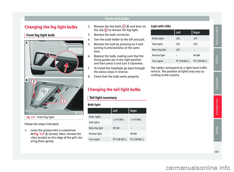
og light bulb Fig. 117
Front fog light. Follow the steps indicated:
Lev
er the gr
oove with a screwdriver
››› Fig. 117 (arrow). Next, remove the
clips located on the edge of the grill, lev-
ering them gently.
1. Remove the two bolts
1 and l
ever on
the c lip 2 to remove the fog light.
R emo
v
e the bulb connector.
Turn the bulb holder to the left and pull.
Remove the bulb by pressing on it and
turning it anticlockwise at the same
time.
Replace the bulb, making sure that the
fixing guides are in the right position
and then press it and turn it clockwise.
To install the headlight go back through
the above steps in reverse.
Check that the bulb works properly.
Changing the tail light bulbs Tail
light summary Bulb light
LeftRight
Brake lights2 x P21WLL2 x P21WLLSide lights
Retro fog lightW21W–
Reverse light–W16W
Turn signalPY 21W NA LLPY 21W NA LL2.
3.
4.
5.
6.
7
8.
Light with LEDs
LeftRight
Brake lightsLEDLED
Side lightsLEDLED
Retro fog lightLED–
Reverse light–W16W
Turn signalPY 21W NA LLPY 21W NA LL The tables correspond to a right-hand traffic
vehic
l
e. The position of lights may vary ac-
cording to the country.
109
Technical data
Advice
Operation
Emergencies
Safety
Page 121 of 312
Instruments and warning/control lamps
Time
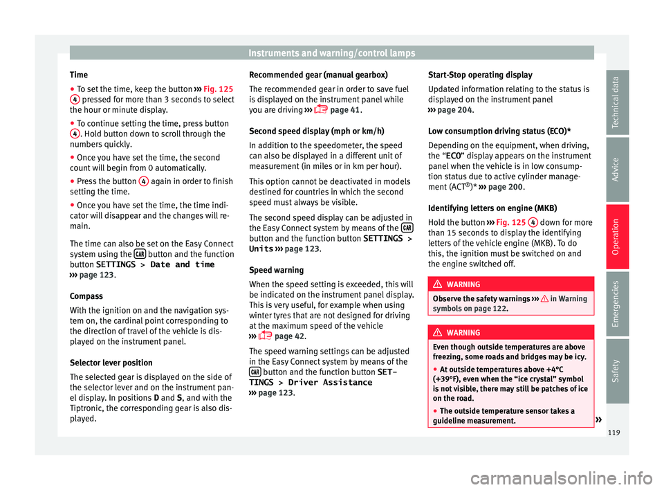
● To set the time, keep the button ››
› Fig. 125
4 pressed for more than 3 seconds to select
the hour or minut e di
s
play.
● To continue setting the time, press button
4 . Hold button down to scroll through the
number s
quic
kly.
● Once you have set the time, the second
count
will begin from 0 automatically.
● Press the button 4 again in order to finish
settin g the time.
● Onc e
you have set the time, the time indi-
cator w
ill disappear and the changes will re-
main.
The time can also be set on the Easy Connect
system using the button and the function
b utt
on
SETTINGS > Date and time
››› page 123.
Compass
With the ignition on and the navigation sys-
tem on, the cardinal point corresponding to
the direction of travel of the vehicle is dis-
played on the instrument panel.
Selector lever position
The selected gear is displayed on the side of
the selector lever and on the instrument pan-
el display. In positions D and S, and with the
Tiptronic, the corresponding gear is also dis-
played. Recommended gear (manual gearbox)
The r
ecommended g
ear in order to save fuel
is displayed on the instrument panel while
you are driving ›››
page 41.
Second speed display (mph or km/h)
In addition to the speedometer, the speed
can also be displayed in a different unit of
measurement (in miles or in km per hour).
This option cannot be deactivated in models
destined for countries in which the second
speed must always be visible.
The second speed display can be adjusted in
the Easy Connect system by means of the button and the function button SETTINGS >
Units › ›
›
page 123.
Speed warning
When the speed setting is exceeded, this will
be indicated on the instrument panel display.
This is very useful, for example when using
winter tyres that are not designed for driving
at the maximum speed of the vehicle
››› page 42.
The speed warning settings can be adjusted
in the Easy Connect system by means of the button and the function button SET-
TINGS > Driver Assistance
› ›
›
page 123. Start-Stop operating display
Updat
ed information relating to the status is
displayed on the instrument panel
››› page 204.
Low consumption driving status (ECO)*
Depending on the equipment, when driving,
the “ ECO” display appears on the instrument
panel when the vehicle is in low consump-
tion status due to active cylinder manage-
ment (ACT ®
)* ››› page 200.
Identifying letters on engine (MKB)
Hold the button ››› Fig. 125 4 down for more
th an 15 sec
ond
s to display the identifying
letters of the vehicle engine (MKB). To do
this, the ignition must be switched on and
the engine switched off. WARNING
Observe the safety warnings ›››
in Warning
symbol s on p
age 122. WARNING
Even though outside temperatures are above
freez in
g, some roads and bridges may be icy.
● At outside temperatures above +4°C
(+39°F), even when the “ice c
rystal” symbol
is not visible, there may still be patches of ice
on the road.
● The outside temperature sensor takes a
guideline meas
urement. » 119
Technical data
Advice
Operation
Emergencies
Safety
Page 124 of 312
Operation
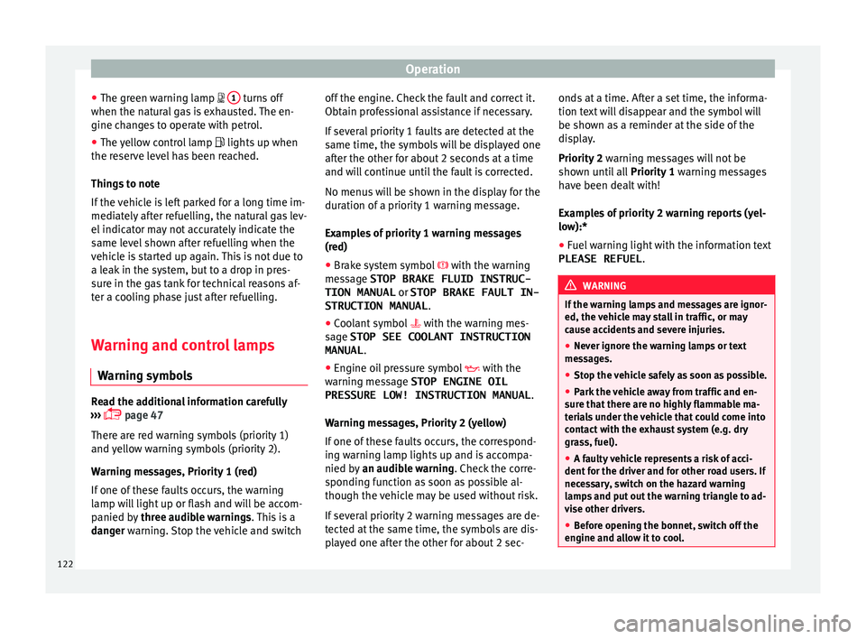
● The gr een w
arnin
g lamp 1 turns off
when the n at
ur
al gas is exhausted. The en-
gine changes to operate with petrol.
● The yellow control lamp lights up when
the re
serve level has been reached.
Things to note
If the vehicle is left parked for a long time im-
mediately after refuelling, the natural gas lev-
el indicator may not accurately indicate the
same level shown after refuelling when the
vehicle is started up again. This is not due to
a leak in the system, but to a drop in pres-
sure in the gas tank for technical reasons af-
ter a cooling phase just after refuelling.
Warning and control lamps
Warning symbo
lsRead the additional information carefully
› ›
›
page 47
There are red warning symbols (priority 1)
and yellow warning symbols (priority 2).
Warning messages, Priority 1 (red)
If one of these faults occurs, the warning
lamp will light up or flash and will be accom-
panied by three audible warnings. This is a
danger warning. Stop the vehicle and switch off the engine. Check the fault and correct it.
Obtain pr
ofessional assistance if necessary.
If several priority 1 faults are detected at the
same time, the symbols will be displayed one
after the other for about 2 seconds at a time
and will continue until the fault is corrected.
No menus will be shown in the display for the
duration of a priority 1 warning message.
Examples of priority 1 warning messages
(red)
● Brake system symbol with the warnin
g
message STOP BRAKE FLUID INSTRUC-
TION MANUAL or STOP BRAKE FAULT IN-
STRUCTION MANUAL .
● Coolant symbol with the warnin
g mes-
sage STOP SEE COOLANT INSTRUCTION
MANUAL .
● Engine oil pressure symbol with the
warnin
g message STOP ENGINE OIL
PRESSURE LOW! INSTRUCTION MANUAL .
Warning messages, Priority 2 (yellow)
If one of these faults occurs, the correspond-
ing warning lamp lights up and is accompa-
nied by an audible warning. Check the corre-
sponding function as soon as possible al-
though the vehicle may be used without risk.
If several priority 2 warning messages are de-
tected at the same time, the symbols are dis-
played one after the other for about 2 sec- onds at a time. After a set time, the informa-
tion text
will disappear and the symbol will
be shown as a reminder at the side of the
display.
Priority 2 warning messages will not be
shown until all Priority 1 warning messages
have been dealt with!
Examples of priority 2 warning reports (yel-
low):*
● Fuel warning light with the information text
PLEASE REFUEL . WARNING
If the warning lamps and messages are ignor-
ed, the v ehic
le may stall in traffic, or may
cause accidents and severe injuries.
● Never ignore the warning lamps or text
mess
ages.
● Stop the vehicle safely as soon as possible.
● Park the vehicle away from traffic and en-
sure th
at there are no highly flammable ma-
terials under the vehicle that could come into
contact with the exhaust system (e.g. dry
grass, fuel).
● A faulty vehicle represents a risk of acci-
dent for the driv
er and for other road users. If
necessary, switch on the hazard warning
lamps and put out the warning triangle to ad-
vise other drivers.
● Before opening the bonnet, switch off the
engine and al
low it to cool.122
Page 134 of 312

Operation
For the sake of the environment
Please dispose of your used batteries correct-
ly and w ith r
espect for the environment.Synchronising the remote control key
If it is not possible to unlock or lock the door
with the r
emot
e control, it should be re-
synchronised.
While the vehicle is open:
– Press the button 2
› ›
›
Fig. 136 on the re-
mote control.
– Then close the vehicle using the key shaft
within one minute.
Whi
le the vehicle is closed:
– Press the button 1
› ›
›
Fig. 136 on the re-
mote control.
– Then close the vehicle using the key shaft
within one minute.
It
is possible that the vehicle could no longer
be opened and closed with the remote con-
trol if the button is repeatedly pressed out-
side of the effective range of the radio fre-
quency remote control. The remote control
key will have to be resynchronised. Spare remote control keys are available at
your T
echnical Service, where they must be
matched to the locking system.
Up to five remote control keys can be used.
Central locking system Des
cription Read the additional information carefully
›› ›
page 15.
The central locking system enables you to
lock and unlock all doors and the rear lid by
just pushing the button.
Central locking can be activated by using any
of the following options:
● the key, by inserting it into the driver door
cylinder and r ot
ating it in the opening direc-
tion. Depending on the vehicle version, ei-
ther all doors will be unlocked or only the
driver door will be unlocked. All doors will be
locked on locking the vehicle using the key.
● the interior central lock button
›››
page 134.
● the radio frequency remote control , usin
g
the buttons on the key ›››
page 130.
Various functions are available to improve
the vehicle safety: Locking system “Safe*”
Selective* u
nlocking system
Self-locking system to prevent involunta-
ry unlocking
Automatic speed dependent locking and
unlocking system*
Emergency unlocking system
Unlocking the vehicle* Press the button ››› Fig. 136 on the re-
mote control to unlock all the doors and
the rear lid.
Locking the vehicle* Press the button ››› Fig. 136 on the re-
mote control to lock all doors and the
rear lid or turn the key in the door to lock
all doors and the rear lid. WARNING
● Loc k
ing from the outside carelessly or with-
out good visibility may lead to bruising, par-
ticularly in the case of children.
● When locking a vehicle, never leave chil-
dren un
accompanied inside, as from the out-
side it will be difficult to provide assistance if
required.
● Having the doors locked prevents intruders
from gettin
g in, for example when stopped at
a traffic light. –
–
–
–
–
–
–
132
Page 146 of 312
Operation
Sunroof* Intr oduction WARNING
If the sunroof is used negligently or without
pa y
ing due attention, it can cause serious in-
jury.
● Open or close the sunroof and the sun blind
only when no one i
s in their path of move-
ment.
● Never leave any key inside the vehicle
when exitin
g.
● Never leave a child or any other person who
may
need help in the vehicle, especially if
they have access to the vehicle key. If using
they key unattended, they could lock the ve-
hicle, start the engine, switch on the ignition
and activate the sunroof.
● After switching off, it is still possible to
open or close the s
unroof during a short
space of time provided that neither the driver
nor passenger door is opened. CAUTION
● To pr ev
ent damage, during winter tempera-
tures remove any ice or snow that might be
on the car roof before opening the sunroof or
adjusting the tilt position.
● Before leaving the vehicle or in case of rain-
fal
l, always close the sunroof. With the sun-
roof open or in a tilted position, water can en- ter the interior and can cause considerable
dam
ag
e to the electrical system. As a result,
other damage can occur in the vehicle. Note
● Le av
es and other loose objects that accu-
mulate on the sunroof rails should be regular-
ly cleaned away either by hand or with a vac-
uum.
● If the sunroof does not work correctly, the
anti-trap fu
nction will not work either. Con-
tact a specialised workshop. Opening and closing the sunroof
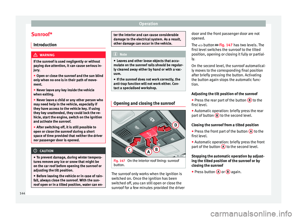
Fig. 147
On the interior roof lining: sunroof
b utt
on. The sunroof only works when the ignition is
sw
it
c
hed on. Once the ignition has been
switched off, you can still open or close the
sunroof for a few minutes provided the driver door and the front passenger door are not
opened.
The button
›
›› Fig. 147 has two levels. The
first level switches the sunroof to the tilted
position, opening or closing it fully or partial-
ly.
On the second level, the sunroof automatical-
ly moves to the corresponding final position
after briefly pressing the button. Activating
the button again stops the automatic func-
tion.
Adjusting the tilt position of the sunroof
● Press the rear part of the button B to the
fir s
t
level.
● Automatic operation: briefly press the rear
part
of button B to the second level.
C lo
s
ing the sunroof from a tilted position
● Press the front part of the button A to the
fir s
t
level.
● Automatic operation: briefly press the front
part
of the button A to the second level.
St op
pin
g the automatic operation by adjust-
ing the tilted position of the sunroof or by
closing the sunroof
● Press button A or
B again.
144
Page 147 of 312
Opening and closing
Opening the sunroof
● Press button C backwards to the first lev-
el .
● Aut om
atic operation to comfort position:
briefly pre
ss button C backwards to the sec-
ond l ev
el
.
Closing the sunroof
● Press button D forwards to the first level.
● Automatic operation: briefly press button
D forwards to the second level.
St op
pin
g the automatic operation during the
opening or closing
● Press button C or
D again.
S u
n b
lind
The sun blind is opened and closed manually
(independently of the sliding sunroof).
Convenience function to open or close the
sunroof*
The sunroof can be opened and closed with
the convenience function, just like the win-
dows:
Using the door lock *
● Hold the key in the door lock of the driver
door in either the unloc
king or locking posi-
tion to open or close the roof in the tilted po-
sition. ●
Rele
ase the key to interrupt this function.
Using the remote control ● Keep the locking/unlocking button pressed
to open/clo
se the roof; if you stop pressing
the button, the opening/closing function is
stopped.
Once all the windows and the sunroof have
closed, all the turn signals flash. During con-
venience closing, the windows and the sun-
roof close at the same time.
Anti-trap function of the panoramic
sliding s
unroof The anti-trap function can reduce the risk of
injur
y
when c
losing the sunroof ››› . If the
s u
nr
oof encounters resistance or an obstacle
when closing, it reopens immediately.
● Check why the sunroof did not close.
● Try to close the sunroof again.
● If the sunroof cannot be closed due to an
obs
tacle or some resistance, it stops at the
corresponding position and then reopens.
For automatic closing, a new closing attempt
might take place.
● If the sunroof is still unable to close, close
it without
the anti-trap function. Closing the sunroof without the anti-trap
function
●
B
efore approx. 5 seconds of having activa-
ted the ro
ll-back function, press the but-
ton ››› Fig. 147 to the second level in the di-
rection of arrow ››› Fig. 147 D until the sun-
r oof
c
loses completely.
● The sunroof closes without the anti-trap
function int
ervening!
● If the sunroof will still not close, visit a spe-
ciali
sed workshop. WARNING
Closing the sunroof without the anti-trap
fu nction c
an cause serious injuries.
● Always be careful when closing the sun-
roof.
● No per
son should ever remain in the way of
the sunr
oof, especially when closing without
the anti-trap function.
● The anti-trap function does not prevent fin-
gers
or other parts of the body from becom-
ing trapped against the roof frame and inju-
ries occurring. 145
Technical data
Advice
Operation
Emergencies
Safety