esp Seat Ibiza 2017 Edition 11.17 Workshop Manual
[x] Cancel search | Manufacturer: SEAT, Model Year: 2017, Model line: Ibiza, Model: Seat Ibiza 2017Pages: 312, PDF Size: 6.51 MB
Page 217 of 312
Driver assistance systems
●
The sensor m a
y become damaged or lose
its settings when knocked, for example, dur-
ing a parking manoeuvre. This may compro-
mise the system's efficacy or disconnect it.
● Repairs to the radar sensor require special-
ist
knowledge and special tools. SEAT recom-
mends visiting a SEAT dealership for this pur-
pose.
● A registration plate or plate holder on the
front th
at is larger than the space for the reg-
istration plate, or a registration plate that is
curved or warped can cause the radar to mal-
function.
● Clean away the snow with a brush and the
ice pref
erably with a solvent-free de-icer
spray. Operating the Emergency braking as-
s
i
s
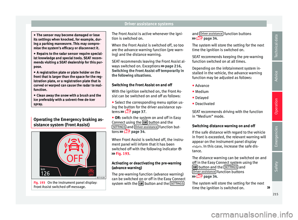
tance system (Front Assist) Fig. 193
On the instrument panel display:
Fr ont As
sist switched off message. The Front Assist is active whenever the igni-
tion i
s
sw
itched on.
When the Front Assist is switched off, so too
are the advance warning function (pre warn-
ing) and the distance warning.
SEAT recommends leaving the Front Assist al-
ways switched on. Exceptions ››› page 216,
Switching the Front Assist off temporarily in
the following situations.
Switching the Front Assist on and off
With the ignition switched on, the Front As-
sist can be switched on and off as follows:
● Select the corresponding menu option us-
ing the butt
on for the driver assistance sys-
tems ›››
page 37.
● OR: switch the system on and off in Easy
Connect
using the button and the
S ET
TINGS and
Driv
er a
s
sistance function but-
t on
s
›››
page 34.
When Front Assist is switched off, the instru-
ment panel will inform that it has been
switched off with the following indicator
››› Fig. 193.
Activating or deactivating the pre-warning
(advance warning)
The pre-warning function (advance warning)
can be switched on or off in the Easy Connect
system with the button and the
S
ET
TINGS and
Driv
er a
s
sistance function buttons
› ›
›
page 34.
The system will store the setting for the next
time the ignition is switched on.
SEAT recommends keeping the pre-warning
function switched on at all times.
Depending on the infotainment system in-
stalled in the vehicle, the advance warning
function may be adjusted as follows:
● Advance
● Medium
● Delayed
● Deactivated
SEAT r
ecommends driving with the function
in “Medium” mode.
Switching distance warning on and off
If the safe distance with regard to the vehicle
in front is exceeded, the relevant warning will
appear on the instrument panel display
. In this case, increase the safe dis-
tance.
The distance warning can be switched on and
off in the Easy Connect system using the button and the
S
ET
TINGS and
Driv er a
s
sistance function buttons
› ›
›
page 34.
The system will store the setting for the next
time the ignition is switched on. »
215
Technical data
Advice
Operation
Emergencies
Safety
Page 222 of 312
Operation
programmed speed and ACC status will be
di s
p
layed ››› Fig. 196.
What ACC settings are possible?
● Setting your speed ›››
page 220.
● Setting your distance ›››
page 220.
● Connecting and activating the ACC
›››
page 220.
● Disconnecting and deactivating the ACC
›››
page 220.
● Adjusting the default distance level at the
star
t of your journey ››› page 220.
● Adjusting the driving profile ›››
page 221.
● Conditions in which the ACC does not react
›››
page 221.
Setting speed
To set your speed, move the third lever loca-
ted in position 1 upwards or downwards un-
ti l
the de
sired speed is shown on the instru-
ment panel display. The speed adjustment is
made at 10 km/h (6 mph) intervals.
Once you are driving , if you wish to set the
current speed as the vehicle’s cruise speed
and activate the ACC, press the button
››› Fig. 199. If you wish to increase or reduce
speed by intervals of 1 km/h (0.6 mph),
move the lever to position 2
›
››
Fig. 198 or
press the button, respectively.
The set speed can be changed when the ve-
hicle is stopped or during driving, as you like. Any modification to the programmed speed
wil
l be shown on the bottom left part of the
instrument panel display ››› Fig. 196.
Setting your distance level
To increase/reduce the distance level, press
the rocker switch towards the left/right
››› Fig. 199 A .
The in s
trument
panel display shows the mod-
ification of the distance level. There are 5 dis-
tance levels to choose from. SEAT recom-
mends level 3. The set distance can be
changed when the vehicle is stopped or dur-
ing driving, as you like ››› .
C onnectin
g and activ
ating the ACC
To connect and activate the ACC, the position
of the gearbox selector lever, the vehicle
speed and the position of the third level of
the ACC must all be taken into account.
● With a manual gearbox, the gearbox selec-
tor lev
er must be in any gear except first, and
speed must be greater than approximately 30
km/h. With an automatic gearbox, the gear-
box selector lever must be in position D or S.
● To activate the ACC, with the third lever in
position 1 press the
butt
on or mo
ve the
third lever of the ACC to position 2 ›››
Fig. 198. At thi s
point, the image of the
ACC on the instrument panel display will
switch to Active mode ››› Fig. 196. When the ACC function is active, the vehicle
trav
el
s at a set speed and distance from the
vehicle ahead. Both speed and distance can
be changed at any time.
Disconnecting and deactivating the ACC
To disconnect the ACC move the lever to the 0 position
›››
Fig. 198
(en
gaged). An ACC
deactivated message appears and the
function is totally deactivated.
If you do not wish to disconnect the ACC, just
to switch it temporarily to inactive mode
(Standby), move the third lever to position 3 ›››
Fig. 198 or pre s
s the brake pedal.
It will also switch to inactive mode (Standby)
if the vehicle is stopped and the driver door
is opened.
Adjusting the default distance level at the
start of your journey.
In wet road conditions, you should always set
a larger distance with regard to the vehicle in
front than when driving in dry conditions.
The following distances can be preselected:
● Very short
● Short
● Media
● Long
● Very long
220
Page 227 of 312
Driver assistance systems
Factors that may affect how the radar sensor
oper at
e
s
If laser sensor operation is impaired, due to
heavy rain, spray, snow or mud, the ACC is
deactivated temporarily. The relevant text
message will appear in the dash panel dis-
play. If necessary, clean the radar sensor
››› Fig. 197.
When the radar sensor begins to operate
properly again, the ACC will automatically be
available again. The message on the instru-
ment panel screen will switch off and the ACC
will be reactivated again.
ACC operation may be affected by a strong ra-
dar reverse reflection, for example in a closed
car park.
Trailer mode
When driving with trailer the ACC controls
less dynamically.
Overheated brakes
If the brakes overheat, for example after
abrupt braking or in long and steep slopes,
the ACC may be deactivated temporarily. The
relevant text message will appear in the dash
panel display. In this case, adaptive cruise
control cannot be activated.
Adaptive cruise control can be reactivated
once brake temperature has cooled suffi-
ciently. The message will disappear from the
instrument panel display. If the message ACCnot available
remain s on for quite a long
time it means that there is a fault. Contact a
specialised workshop. SEAT recommends vis-
iting a SEAT dealership. WARNING
If you do not heed the Press the brake
mes s
age, the vehicle may initiate an involun-
tary movement and could crash into the vehi-
cle ahead. In any event, before driving off,
check that the road is clear. The radar sensor
may not detect obstacles on the road. This
could cause an accident and serious injuries.
If necessary, apply the brake. SEAT Drive Profile*
Intr oduction SEAT Drive Profile enables the driver to
c
hoo
se betw
een four profiles or modes, Nor-
mal , Sport , Eco and Individual , that
modify the behaviour of various vehicle func-
tions, providing different driving experiences.
The Individual profile can be configured
according to personal preferences. The other
profiles are fixed. Description Depending on the equipment fitted in the ve-
hicl
e,
SEAT Drive Profile can operate on the
following functions:
Engine
Depending on the profile selected, the en-
gine responds more spontaneously or more
in harmony with the movements of the accel-
erator. Additionally, when Eco mode is selec-
ted, the Start-stop function is automatically
activated.
In vehicles with automatic transmission, the
gear change points are modified to position
them in lower or higher engine speed ranges.
Additionally, the Eco mode activates the In-
ertia function, enabling consumption to be
further reduced.
In manual gearbox vehicles, Eco mode cau-
ses the gear change recommendation indica-
tions that appear on the instrument panel to
vary, facilitating more efficient driving.
“Dual Ride” suspension
The “Dual Ride” suspension features a com-
fortable suspension in the Eco and Normal
profiles, suitable for daily use. Contrasting
with this it features a sporty suspension in »
225
Technical data
Advice
Operation
Emergencies
Safety
Page 228 of 312
Operation
the Sport profi
l e, suitable for a sporty driv-
ing style. In the Individual profile the sus-
pension can be switched between Normal or
Sport , depending on personal preference.
In the event of a fault in the “Dual Ride” sus-
pension, the following message is displayed
on the instrument panel screen Fault:
damping setting .
Address
Power steering becomes more robust in Sport mode to enable a sportier driving
style.
Air conditioning
In vehicles with Climatronic, this can operate
in eco mode, especially restricting fuel con-
sumption.
Adaptive Cruise Control (ACC)
According to the active driving profile, the ac-
celeration gradient of the adaptive cruise
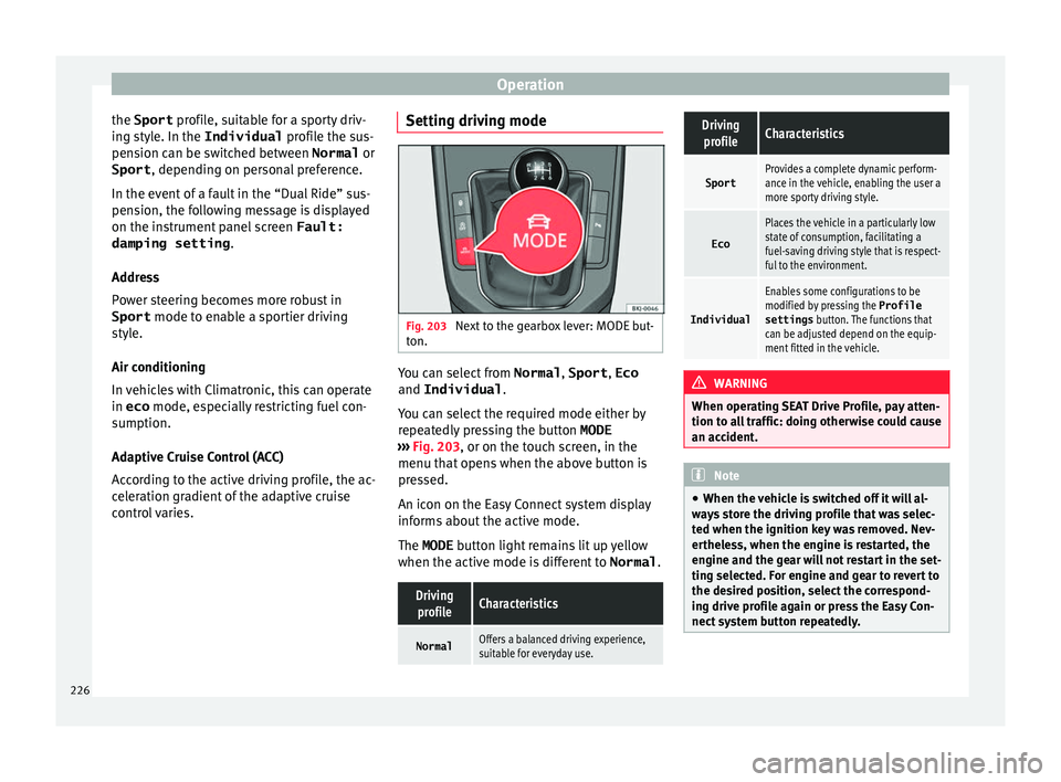
control varies. Setting driving mode Fig. 203
Next to the gearbox lever: MODE but-
t on. You can select from
Normal, Sport, Eco
and Individual .
Y ou c
an sel
ect the required mode either by
repeatedly pressing the button MODE
››› Fig. 203, or on the touch screen, in the
menu that opens when the above button is
pressed.
An icon on the Easy Connect system display
informs about the active mode.
The MODE button light remains lit up yellow
when the active mode is different to Normal.
Driving
profileCharacteristics
NormalOffers a balanced driving experience,
suitable for everyday use.
DrivingprofileCharacteristics
SportProvides a complete dynamic perform-
ance in the vehicle, enabling the user a
more sporty driving style.
Eco
Places the vehicle in a particularly low
state of consumption, facilitating a
fuel-saving driving style that is respect-
ful to the environment.
Individual
Enables some configurations to be
modified by pressing the Profile
settings button. The functions that
can be adjusted depend on the equip-
ment fitted in the vehicle. WARNING
When operating SEAT Drive Profile, pay atten-
tion to a l
l traffic: doing otherwise could cause
an accident. Note
● When the v ehic
le is switched off it will al-
ways store the driving profile that was selec-
ted when the ignition key was removed. Nev-
ertheless, when the engine is restarted, the
engine and the gear will not restart in the set-
ting selected. For engine and gear to revert to
the desired position, select the correspond-
ing drive profile again or press the Easy Con-
nect system button repeatedly. 226
Page 229 of 312
Driver assistance systems
●
Your s peed and driv
ing style must always
be adjusted to visibility, weather, and traffic
conditions.
● The Eco profile is not recommended when
to
wing a vehicle. Kick-down
The kick-down feature allows maximum ac-
cel
er
ation to be reached.
If the eco* ››› page 226 mode has been se-
lected in SEAT Drive Profile*, and the acceler-
ator is pressed beyond a hard point, the en-
gine power is automatically controlled to give
your vehicle maximum acceleration. WARNING
Please note that if the road surface is slip-
pery or w
et, the kick-down feature could
cause the driving wheels to spin, which could
result in skidding. Fatigue detection (break rec-
ommend
ation)*
R el
ated video Fig. 204
Safety Introduction
The Fatigue detection informs the driver
when their driv
in
g beh
aviour shows signs of
fatigue. WARNING
Do not let the comfort afforded by the Fatigue
detection sy s
tem tempt you into taking any
risks when driving. Take regular breaks, suffi-
cient in length when making long journeys.
● The driver always assumes the responsibil-
ity of driv
ing to their full capacity.
● Never drive if you are tired.
● The system does not detect the tiredness of
the driver in al
l circumstances. Consult the in-
formation in the section ››› page 228, System
limitations. ●
In some sit uation
s, the system may incor-
rectly interpret an intended driving manoeu-
vre as driver tiredness.
● No warning is given in the event of the ef-
fect c
alled microsleep!
● Please observe the indications on the in-
strument p
anel and act as is necessary. Note
● Fatigue det ection h
as been developed for
driving on motorways and well paved roads
only.
● If there is a fault in the system, have it
check
ed by a specialised workshop. Function and operation
Fig. 205
On the instrument panel display: fa-
tigue det ection symbo
l
. Fatigue detection determines the driving be-
h
av
iour of
the driver when starting a journey, »
227
Technical data
Advice
Operation
Emergencies
Safety
Page 234 of 312
Operation
● Sw it
c
h off the ignition and switch it on
again.
● OR: accelerate above 10 km/h (6 mph) be-
for
e reducing speed below this number
again.
● OR: place the selector lever in position P
and then mov
e it from this position.
● OR: switch on and off the automatic activa-
tion in the Ea
sy Connect system menu.
The automatic activation with parking aid
miniature indication can be switched on and
off from the Easy Connect system menu
››› page 34:
● Switch the ignition on.
● Select: button > Settings
> Parking
and manoeuvring .
● Select the Automatic activation op-
tion. When the f
u
nction button check box is
activated , the function is on.
If the system has been activated automatical-
ly, an audible sound warning will only be giv-
en when obstacles in front are at a distance
of less than 50 cm. CAUTION
The automatic connection of the Parking Aid
only w
orks when you are driving slowly. If
driving style is not adapted to the circum-
stances, an accident and serious injury or
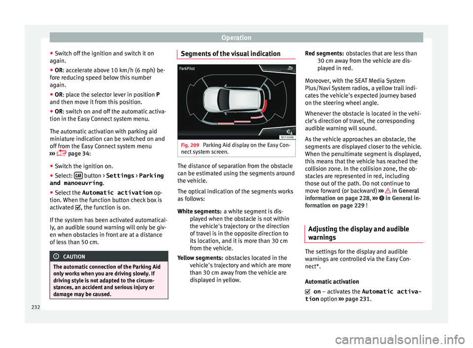
damage may be caused. Segments of the visual indication
Fig. 209
Parking Aid display on the Easy Con-
nect sy
s
tem screen. The distance of separation from the obstacle
c
an be e
s
timated using the segments around
the vehicle.
The optical indication of the segments works
as follows:
a white segment is dis-
played when the obstacle is not within
the vehicle's trajectory or the direction
of travel is in the opposite direction to
its location, and it is more than 30 cm
from the vehicle.
obstacles located in the
vehicle's trajectory and which are more
than 30 cm away from the vehicle are
displayed in yellow.
White segments:
Yellow segments: obstacles that are less than
30 cm aw
ay from the vehicle are dis-
played in red.
Moreover, with the SEAT Media System
Plus/Navi System radios, a yellow trail indi-
cates the vehicle's expected journey based
on the steering wheel angle.
Whenever the obstacle is located in the vehi-
cle’s direction of travel, the corresponding
audible warning will sound.
As the vehicle approaches an obstacle, the
segments are displayed closer to the vehicle.
When the penultimate segment is displayed,
this means that the vehicle has reached the
collision zone. In the collision zone, the ob-
stacles are represented in red, including
those out of the path. Do not continue to
move forward (or backward) ››› in General
inf orm
ation on p
age 228, ››› in General in-
f orm
ation on p
age 229 !
Adjusting the display and audible
warning
s The settings for the display and audible
w
arnin
g
s are controlled via the Easy Con-
nect*.
Automatic activation
on – activates the Automatic activa-
tion option ››› page 231.
Red segments:
232
Page 237 of 312
Driver assistance systems
Note
● It i s
important to take great care and pay
special attention if you are not yet familiar
with the system.
● Rear assist will not be available if the vehi-
cle's
rear lid is open. Instructions for use
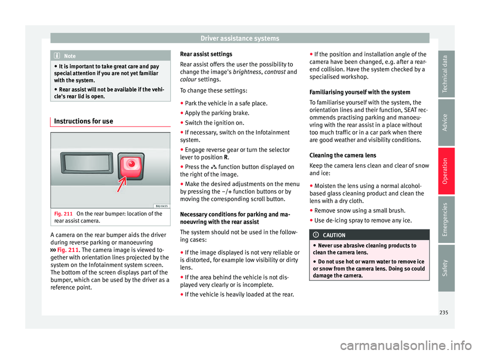
Fig. 211
On the rear bumper: location of the
r e
ar a
ssist camera. A camera on the rear bumper aids the driver
durin
g r
ev
erse parking or manoeuvring
››› Fig. 211. The camera image is viewed to-
gether with orientation lines projected by the
system on the Infotainment system screen.
The bottom of the screen displays part of the
bumper, which can be used by the driver as a
reference point. Rear assist settings
Rear a
ssist offers the user the possibility to
change the image's brightness, contrast and
colour settings.
To change these settings:
● Park the vehicle in a safe place.
● Apply the parking brake.
● Switch the ignition on.
● If necessary, switch on the Infotainment
syst
em.
● Engage reverse gear or turn the selector
lever t
o position R.
● Press the function b
utton displayed on
the right of the image.
● Make the desired adjustments on the menu
by pr
essing the –/+ function buttons or by
moving the corresponding scroll button.
Necessary conditions for parking and ma-
noeuvring with the rear assist
The system should not be used in the follow-
ing cases:
● If the image displayed is not very reliable or
is di
storted, for example low visibility or dirty
lens.
● If the area behind the vehicle is not dis-
pla
yed very clearly or is incomplete.
● If the vehicle is heavily loaded at the rear. ●
If the pos
ition and installation angle of the
camera have been changed, e.g. after a rear-
end collision. Have the system checked by a
specialised workshop.
Familiarising yourself with the system
To familiarise yourself with the system, the
orientation lines and their function, SEAT rec-
ommends practising parking and manoeu-
vring with the rear assist in a place without
too much traffic or in a car park when there
are good weather and visibility conditions.
Cleaning the camera lens
Keep the camera lens clean and clear of snow
and ice:
● Moisten the lens using a normal alcohol-
based gl
ass cleaning product and clean the
lens with a dry cloth.
● Remove snow using a small brush.
● Use de-icing spray to remove any ice. CAUTION
● Never u se abr
asive cleaning products to
clean the camera lens.
● Do not use hot or warm water to remove ice
or snow fr
om the camera lens. Doing so could
damage the camera. 235
Technical data
Advice
Operation
Emergencies
Safety
Page 239 of 312
Towing bracket device
Towing bracket device
T o
w
ing bracket device*
Introduction The towing bracket device fitted to your vehi-
cl
e, be it
factory-fitted or a genuine SEAT ac-
cessory, meets all the national technical and
legal requirements for towing.
Your vehicle is fitted with a 13-pin connector
for the electrical connection between the
trailer and the vehicle. If the trailer is equip-
ped with a 7-pin connector you can use the
corresponding adaptor, which is available as
a genuine SEAT accessory.
The maximum authorised towing load is 50
kg. WARNING
● Bef or
e each journey, make sure that the de-
tachable ball joint is properly fitted and se-
cured in its housing.
● If the detachable ball joint is not properly
fitted and secur
ed, do not use it.
● Do not use the towing bracket device for
tow
ing if it is damaged or has missing parts.
● Do not modify or adapt the towing device
connection.
● Never u
nhook the detachable ball joint
when the trail
er is hitched. CAUTION
Handle the detachable ball joint with care in
order t o av
oid damaging the bumper paint-
work. Note
Towing the vehicle with the detachable ball
joint ›
›› page 102. Description
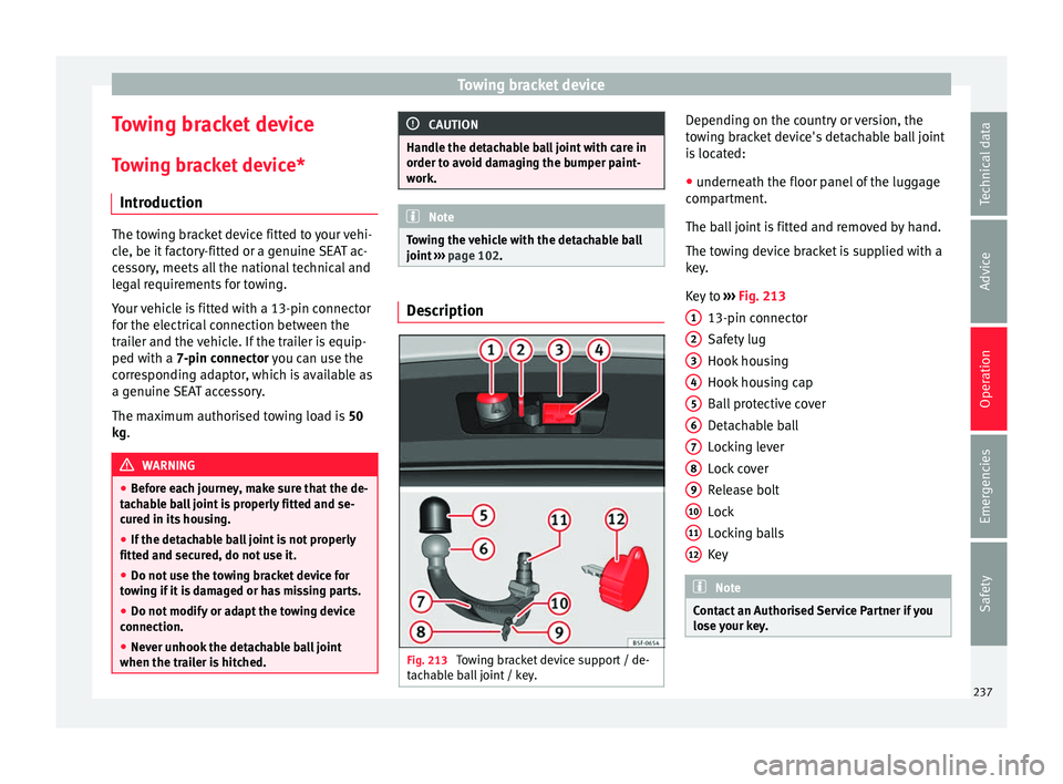
Fig. 213
Towing bracket device support / de-
t ac h
able ball joint / key. Depending on the country or version, the
t
o
w
ing bracket device's detachable ball joint
is located:
● underneath the floor panel of the luggage
compar
tment.
The ball joint is fitted and removed by hand.
The towing device bracket is supplied with a
key.
Key to ››› Fig. 213
13-pin connector
Safety lug
Hook housing
Hook housing cap
Ball protective cover
Detachable ball
Locking lever
Lock cover
Release bolt
Lock
Locking balls
Key Note
Contact an Authorised Service Partner if you
lose y
our key. 1
2
3
4
5
6
7
8
9
10
11
12
237
Technical data
Advice
Operation
Emergencies
Safety
Page 244 of 312
Operation
Trailer towing Wh at
do
you need to bear in mind
when towing a trailer? Your vehicle may be used to tow a trailer
when fitted w
ith the c
orrect equipment.
If you wish to retrofit a towing bracket, con-
sult ››› page 245.
Connectors
Your vehicle is fitted with a 13-pin connector
for the electrical connection between the
trailer and the vehicle.
If the trailer has a 7-pin plug you will need to
use an adapter cable. It is available at any
Technical Service.
Trailer weight/drawbar load
Never exceed the authorised trailer weight. If
you do not load the trailer up to the maxi-
mum permitted trailer weight, you can then
climb correspondingly steeper slopes.
The maximum trailer weights listed are only
applicable for altitudes up to 1000 m above
sea level. With increasing altitude the engine
power and therefore the vehicle climbing
ability are impaired because of the reduced
air density. The maximum trailer weight has
to be reduced accordingly. The weight of the
vehicle and trailer combination must be re- duced by 10% for every further 1000 m (or
par
t
thereof). The gross combination weight
is the actual weight of the laden vehicle plus
the actual weight of the laden trailer. When
possible, operate the trailer with the maxi-
mum permitted drawbar load on the ball joint
of the towing bracket, but do not exceed the
specified limit.
The figures for trailer weights and drawbar
loads that are given on the data plate of the
towing bracket are for certification purposes
only. The correct towing bracket figures for
your specific model, which may be lower than
these figures, are given in the vehicle docu-
mentation or on ››› page 281, Technical
specifications.
Distributing the load
Distribute loads in the trailer so that heavy
objects are as near to the axle as possible.
Loads carried in the trailer must be secured
to prevent them moving.
Tyre pressure
The maximum permissible tyre pressure val-
ues are shown on the sticker on the rear part
of the left front door frame. Set the tyre pres-
sure of the trailer tyres in accordance with the
trailer manufacturer's recommendations. Exterior mirrors
Check whether
you can see enough of the
road behind the trailer with the standard rear
vision mirrors. If this is not the case, you
should have additional exterior mirrors fitted.
Both exterior mirrors should be mounted on
hinged extension brackets. Adjust the mirrors
to give sufficient vision to the rear.
Tow rope
Always use a cable between the vehicle and
the trailer ››› page 243.
Trailer rear lights
The trailer's rear lights should comply with
the statutory safety regulations ››› page 243. WARNING
Never transport people in a trailer. This could
re s
ult in fatal accidents. Note
● To w
ing a trailer places additional demands
on the vehicle. We recommend additional
services between the normal inspection inter-
vals if the vehicle is used frequently for tow-
ing a trailer.
● Find out whether special regulations apply
to to
wing a trailer in your country. 242
Page 245 of 312
Towing bracket device
Hitching and connecting the trailer Fig. 224
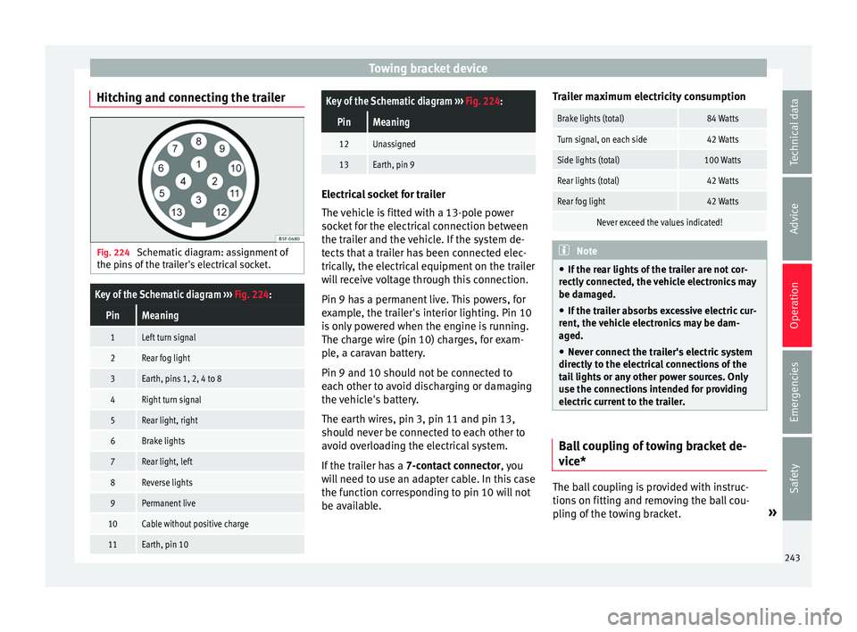
Schematic diagram: assignment of
the pins of the trailer's electrical socket.
Key of the Schematic diagram ››› Fig. 224:
PinMeaning
1Left turn signal
2Rear fog light
3Earth, pins 1, 2, 4 to 8
4Right turn signal
5Rear light, right
6Brake lights
7Rear light, left
8Reverse lights
9Permanent live
10Cable without positive charge
11Earth, pin 10
Key of the Schematic diagram ››› Fig. 224:
PinMeaning
12Unassigned
13Earth, pin 9 Electrical socket for trailer
The v
ehic
le is fitted with a 13-pole power
socket for the electrical connection between
the trailer and the vehicle. If the system de-
tects that a trailer has been connected elec-
trically, the electrical equipment on the trailer
will receive voltage through this connection.
Pin 9 has a permanent live. This powers, for
example, the trailer's interior lighting. Pin 10
is only powered when the engine is running.
The charge wire (pin 10) charges, for exam-
ple, a caravan battery.
Pin 9 and 10 should not be connected to
each other to avoid discharging or damaging
the vehicle's battery.
The earth wires, pin 3, pin 11 and pin 13,
should never be connected to each other to
avoid overloading the electrical system.
If the trailer has a 7-contact connector , you
will need to use an adapter cable. In this case
the function corresponding to pin 10 will not
be available. Trailer maximum electricity consumption
Brake lights (total)84 Watts
Turn signal, on each side42 Watts
Side lights (total)100 Watts
Rear lights (total)42 Watts
Rear fog light42 Watts
Never exceed the values indicated!
Note
● If the r e
ar lights of the trailer are not cor-
rectly connected, the vehicle electronics may
be damaged.
● If the trailer absorbs excessive electric cur-
rent, the v
ehicle electronics may be dam-
aged.
● Never connect the trailer's electric system
directly t
o the electrical connections of the
tail lights or any other power sources. Only
use the connections intended for providing
electric current to the trailer. Ball coupling of towing bracket de-
v
ic
e* The ball coupling is provided with instruc-
tion
s
on fittin
g and removing the ball cou-
pling of the towing bracket. »
243
Technical data
Advice
Operation
Emergencies
Safety