Seat Ibiza 5D 2007 Owner's manual
Manufacturer: SEAT, Model Year: 2007, Model line: Ibiza 5D, Model: Seat Ibiza 5D 2007Pages: 272, PDF Size: 8.32 MB
Page 221 of 272
If and when219
Safety First
Operating instructions
Tips and Maintenance
Te c h n i c a l D a t a
Some of the electrical items listed in
the table are only fitted on certain
models or are optional extras.
Please note that the above list, while correct at the time of printing, is subject
to alterations.
Bulb changeGeneral notesBefore changing any bulb, first turn off the equipment concerned.
Do not touch the bulb glass. Fingerprints vaporise in the heat, causing a
reduction in the bulb life and condensation on the mirror surface, thus
reducing efficiency.
A bulb should only be replaced by one of the same type. The type is inscribed
on the bulb, either on the glass part or on the base.
It is highly recommended to keep a box of spare bulbs in the vehicle. At the
very least, the bulbs that most affect road safety should have spares in the
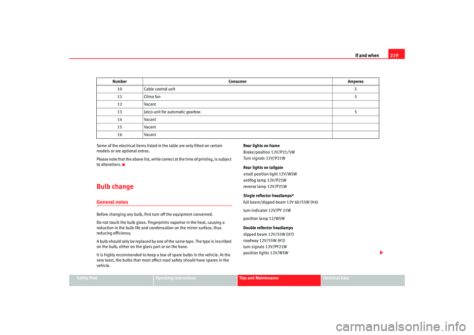
vehicle. Rear lights on frame
Brake/position 12V/P21/5W
Turn signals 12V/P21W
Rear lights on tailgate
small position light 12V/W5W
antifog lamp 12V/P21W
reverse lamp 12V/P21W
Single reflector headlamps*
full beam/dipped beam 12V 60/55W (H4)
turn indicator 12V/PY 21W
position lamp 12/W5W
Double reflector headlamps
dipped beam 12V/55W (H7)
roadway 12V/55W (H3)
turn signals 12V/PY21W
position lights 12V/W5W
10
Cable control unit 5
11 Clima fan 5
12 Vacant
13 Jatco unit for automatic gearbox 5
14 Vacant
15 Vacant
16 Vacant
Number
Consumer Amperes
IBI_ANG_0707 Seite 219 Montag, 6. August 2007 3:59 15
Page 222 of 272
If and when
220Xenon headlights
9)
Dipped beam 12V/35W (D1S)
10)
roadway 12V/55W (H7)
turn signals 12V/PY21W
position lights 12V/W5W
Fog lights*
Fog lights 12V/55W (H3)
Registration plate light
Registration plate light - C5W
Caution
•
The halogen lamps (H3, H7...) are pressurised and might explode on
changing them.
•
Therefore protective gloves and glas ses should be worn when changing a
halogen lamp.Note
•
Due to the difficulty in accessing the lamps, any replacement work should
be done by a SEAT dealer. However, we shall explain how to change these
lamps, except for the xenon lights*.
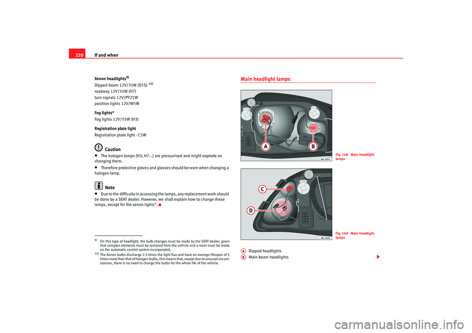
Main headlight lamps
Dipped headlights
Main beam headlights
9)On this type of headlight, the bulb changes must be made by the SEAT dealer, given
that complex elements must be removed from the vehicle and a reset must be made
on the automatic control system incorporated.10)The Xenon bulbs discharge 2.5 times the light flux and have an average lifespan of 5
times more than that of halo gen bulbs, this means that, except due to unusual circum-
stances, there is no need to change the bulbs for the whole life of the vehicle.
Fig. 148 Main headlight
lampsFig. 149 Main headlight
lamps
AAAB
IBI_ANG_0707 Seite 220 Montag, 6. August 2007 3:59 15
Page 223 of 272
If and when221
Safety First
Operating instructions
Tips and Maintenance
Te c h n i c a l D a t a
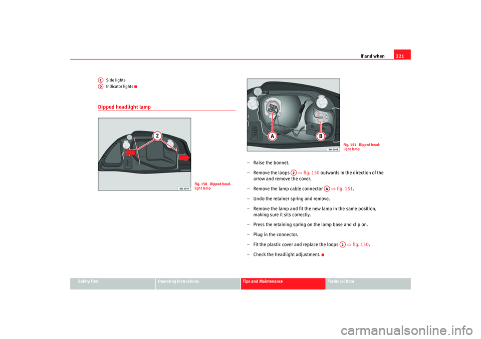
Side lights
Indicator lights
Dipped headlight lamp
– Raise the bonnet.
– Remove the loops
⇒fig. 150 outwards in the direction of the
arrow and remove the cover.
– Remove the lamp cable connector ⇒fig. 151.
– Undo the retainer spring and remove.
– Remove the lamp and fit the new lamp in the same position, making sure it sits correctly.
– Press the retaining spring on the lamp base and clip on.
– Plug in the connector.
– Fit the plastic cover and replace the loops ⇒fig. 150 .
– Check the headlight adjustment.
ACAD
Fig. 150 Dipped head-
light lamp
Fig. 151 Dipped head-
light lamp
A2
AA
A2
IBI_ANG_0707 Seite 221 Montag, 6. August 2007 3:59 15
Page 224 of 272
If and when
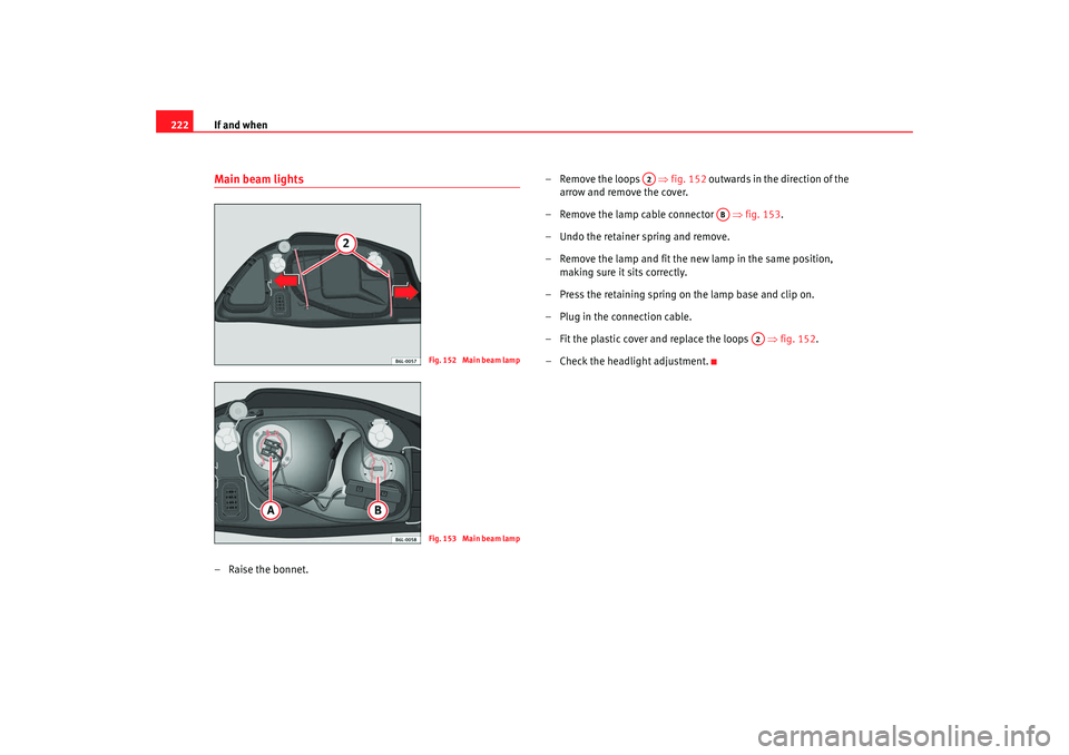
222Main beam lights– Raise the bonnet. – Remove the loops
⇒fig. 152 outwards in the direction of the
arrow and remove the cover.
– Remove the lamp cable connector ⇒fig. 153 .
– Undo the retainer spring and remove.
– Remove the lamp and fit the new lamp in the same position, making sure it sits correctly.
– Press the retaining spring on the lamp base and clip on.
– Plug in the connection cable.
– Fit the plastic cover and replace the loops ⇒fig. 152.
– Check the headlight adjustment.
Fig. 152 Main beam lampFig. 153 Main beam lamp
A2
AB
A2
IBI_ANG_0707 Seite 222 Montag, 6. August 2007 3:59 15
Page 225 of 272
If and when223
Safety First
Operating instructions
Tips and Maintenance
Te c h n i c a l D a t a
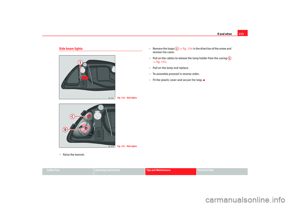
Side beam lights–Raise the bonnet. – Remove the loops
⇒fig. 154 in the direction of the arrow and
remove the cover.
– Pull on the cables to release the lamp holder from the casing ⇒fig. 155.
– Pull on the lamp and replace.
– To assemble proceed in reverse order.
– Fit the plastic cover and secure the loop.
Fig. 154 Side lightsFig. 155 Side lights
A1
AC
IBI_ANG_0707 Seite 223 Montag, 6. August 2007 3:59 15
Page 226 of 272
If and when
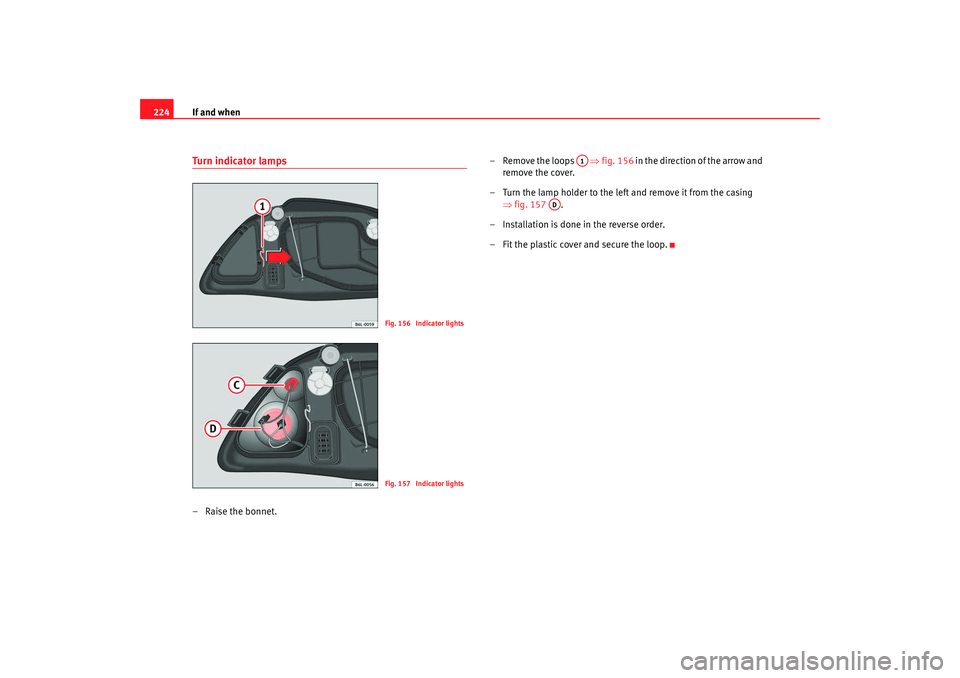
224Turn indicator lamps– Raise the bonnet. – Remove the loops
⇒fig. 156 in the direction of the arrow and
remove the cover.
– Turn the lamp holder to the left and remove it from the casing ⇒fig. 157 .
– Installation is done in the reverse order.
– Fit the plastic cover and secure the loop.
Fig. 156 Indicator lightsFig. 157 Indicator lights
A1
AD
IBI_ANG_0707 Seite 224 Montag, 6. August 2007 3:59 15
Page 227 of 272
If and when225
Safety First
Operating instructions
Tips and Maintenance
Te c h n i c a l D a t a
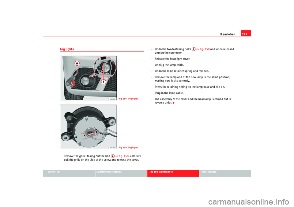
Fog lights– Remove the grille, taking out the bolt ⇒fig. 158 , carefully
pull the grille on the side of the screw and release the cover. – Undo the two fastening bolts
⇒fig. 158 and when released
unplug the connector.
– Release the headlight cover.
– Unplug the lamp cable.
– Undo the lamp retainer spring and remove.
– Remove the lamp and fit the new lamp in the same position, making sure it sits correctly.
– Press the retaining spring on the lamp base and clip on.
–Plug in the lamp cable.
–The assembly of the cover and the headlamp is carried out in
reverse order.
Fig. 158 Fog lightsFig. 159 Fog lights
AA
AF
IBI_ANG_0707 Seite 225 Montag, 6. August 2007 3:59 15
Page 228 of 272
If and when
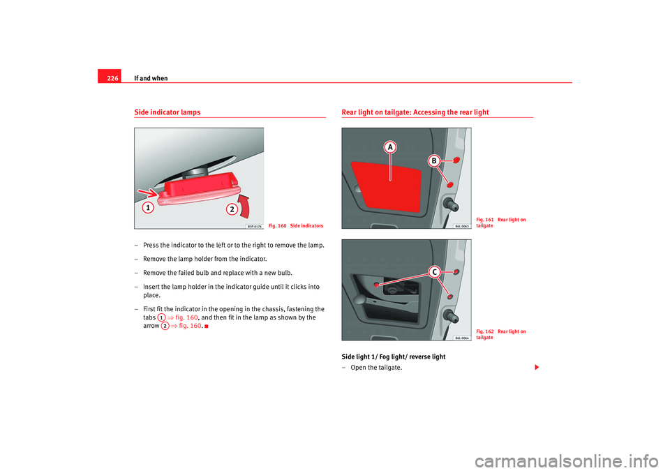
226Side indicator lamps– Press the indicator to the left or to the right to remove the lamp.
– Remove the lamp holder from the indicator.
– Remove the failed bulb and replace with a new bulb.
– Insert the lamp holder in the indicator guide until it clicks into
place.
– First fit the indicator in the opening in the chassis, fastening the tabs ⇒fig. 160, and then fit in the lamp as shown by the
arrow ⇒fig. 160.
Rear light on tailgate: Accessing the rear lightSide light 1/ Fog light/ reverse light
–Open the tailgate.
Fig. 160 Side indicators
A1A2
Fig. 161 Rear light on
tailgateFig. 162 Rear light on
tailgate
IBI_ANG_0707 Seite 226 Montag, 6. August 2007 3:59 15
Page 229 of 272
If and when227
Safety First
Operating instructions
Tips and Maintenance
Te c h n i c a l D a t a
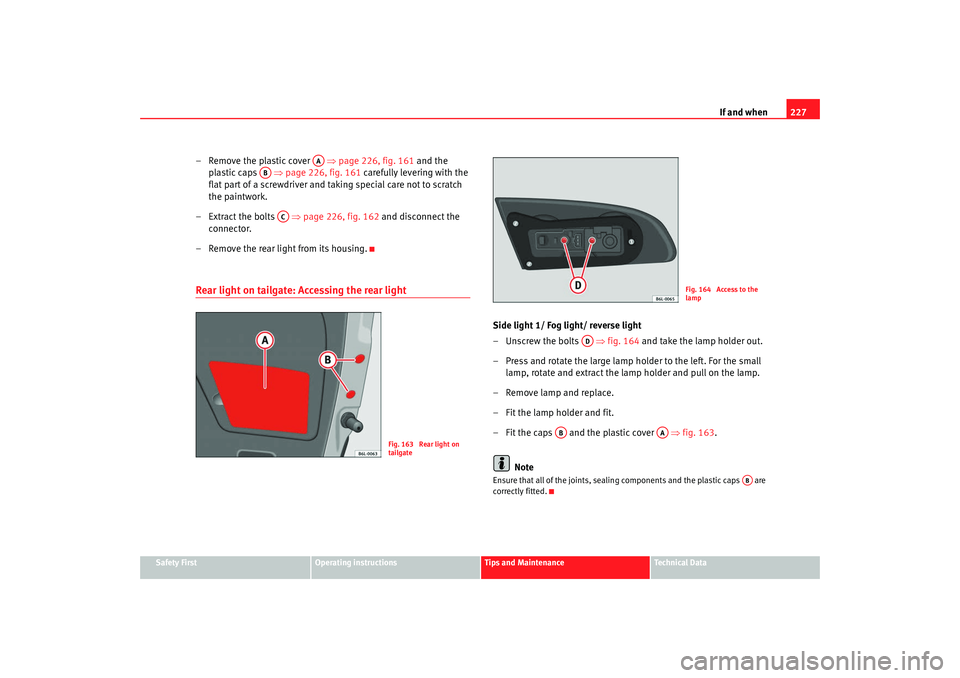
– Remove the plastic cover ⇒page 226, fig. 161 and the
plastic caps ⇒page 226, fig. 161 carefully levering with the
flat part of a screwdriver and ta king special care not to scratch
the paintwork.
– Extract the bolts ⇒page 226, fig. 162 and disconnect the
connector.
– Remove the rear light from its housing.Rear light on tailgate: Accessing the rear light
Side light 1/ Fog light/ reverse light
– Unscrew the bolts ⇒fig. 164 and take the lamp holder out.
– Press and rotate the large lamp holder to the left. For the small lamp, rotate and extract the lamp holder and pull on the lamp.
– Remove lamp and replace.
– Fit the lamp holder and fit.
– Fit the caps and the plastic cover ⇒fig. 163 .
NoteEnsure that all of the joints, sealing components and the plastic caps are
correctly fitted.
AA
AB
AC
Fig. 163 Rear light on
tailgate
Fig. 164 Access to the
lamp
AD
AB
AA
AB
IBI_ANG_0707 Seite 227 Montag, 6. August 2007 3:59 15
Page 230 of 272
If and when
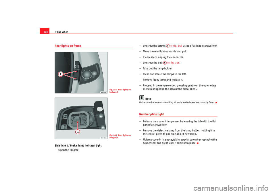
228Rear lights on frameSide light 2/ Brake light/ Indicator light
– Open the tailgate. – Unscrew the screws
⇒fig. 165 using a flat-blade screwdriver.
– Move the rear light outwards and pull.
– If necessary, unplug the connector.
– Unscrew the bolt ⇒fig. 166.
– Take out the lamp holder.
– Press and rotate the lamps to the left.
– Remove faulty lamp and replace it.
– Proceed in the reverse order, pressing gently on the outer edge of the rear light (in the area of the metal clips).
Note
Make sure that when assembling all se als and rubbers are correctly fitted.Number plate light– Release transparent lamp cover by levering the tab with the flat
part of a screwdriver.
– Remove the defective lamp from the lamp holder, holding it in the centre, press to one side and fit new lamp.
– Fit lamp cover in its space, taking special care when replacing the rubber seal and press until it clicks into place.
Fig. 165 Rear lights on
bodyworkFig. 166 Rear lights on
bodywork
AF
AG
IBI_ANG_0707 Seite 228 Montag, 6. August 2007 3:59 15