Seat Ibiza 5D 2012 Owner's manual
Manufacturer: SEAT, Model Year: 2012, Model line: Ibiza 5D, Model: Seat Ibiza 5D 2012Pages: 280, PDF Size: 3.66 MB
Page 221 of 280
219
If and when
If you have a puncture on one of the front wheels when using snow chains,
fit the compact temporary spare wheel in place of one of the rear wheels.
You can then attach the snow chains to the wheel taken from the rear and
use this wheel to replace the punctured front wheel.
WARNING
● The tyre pressures must be checked and corrected as soon as possi-
ble after fitting the temporary spare wheel.
● Do not drive faster than 80 km/h (50 mph). Higher speeds can cause
an accident.
● Avoid heavy acceleration, hard braking and fast cornering. Risk of ac-
cident.
● Never use more than one temporary spare wheel at the same time,
risk of accident.
● No other type of tyre (normal summer or winter tyre) may be fitted on
the compact temporary spare wheel rim.
Tyre repair kit*
The tyre repair kit (for vehicles not including a temporary
spare wheel) is stored under the floor panel in the luggage
compartment. In the event of a punctured tyre, your vehicle is equipped with the Tyre Mo-
bility System (tyre repair kit).
The tyre repair kit consists of a container with sealing product to repair the
puncture and a compressor to generate the required tyre pressure. The kit
will reliably seal punctures up to a size of about 4 mm caused by the pene-
tration of a foreign body into the tyre.
Note
● Seek professional assistance if the repair of a tyre puncture is not possi-
ble with the sealing product.
Wheel change Preparation work
What you must do before changing a wheel.
– If you have a flat tyre or puncture, park the vehicle as far away
from the flow of traffic as possible. Choose a location that is as
level as possible.
– All vehicle occupants should leave the vehicle. They should
wait in a safe area (for instance behind the roadside crash barri-
er).
– Switch the engine off. Switch the hazard warning lights on and
place the warning triangles in position.
– Apply the handbrake firmly.
– Engage the first gear , or put the selector lever to position P for
those vehicles with an automatic gearbox.
– If you are towing a trailer, unhitch it from your vehicle.
– Take the vehicle tools and the spare wheel out of the luggage
compartment.
Safety FirstOperating InstructionsPractical TipsTechnical Specifications
Page 222 of 280
220If and when
WARNING
Switch on the hazard warning lights and place the warning triangles in
position. This is for your own safety and also warns other road users.
CAUTION
If you have to change the wheel on a slope, it is essential to lock the parallel
wheel on the same axle as that to be changed, with a wedge or similar in
order to immobilise the vehicle.
Note
Please observe legal requirements when doing so.
Changing a wheel
Change the wheel as described below
– Remove the hub caps or the integral trim .
– Slacken the wheel bolts .
– Raise the vehicle with the jack at the corresponding point.
– Remove the wheel and then fit the spare wheel.
– Lower the vehicle.
– Tighten the wheel bolts firmly with the box spanner.
– Replace the hub cap. After changing a wheel
After changing the wheel there are still tasks to complete.
– Put the tools and jack back in the luggage compartment.
– Place the wheel with the defective tyre in the luggage compart-
ment and secure it.
– Check the tyre pressure of the newly fitted tyre as soon as pos-
sible.
– Have the tightening torque of the wheel bolts checked as soon
as possible with a torque wrench. The prescribed torque must
be 120 Nm.
Note
● If you notice that the wheel bolts are corroded and difficult to turn when
changing a wheel, they must be replaced before having the wheel bolt tight-
ening torque checked.
● For safety reasons, drive at moderate speeds until the wheel bolt tight-
ening torque has been checked.
Page 223 of 280
221
If and when
Wheel covers*
The wheel covers must be removed for access to the wheel
bolts
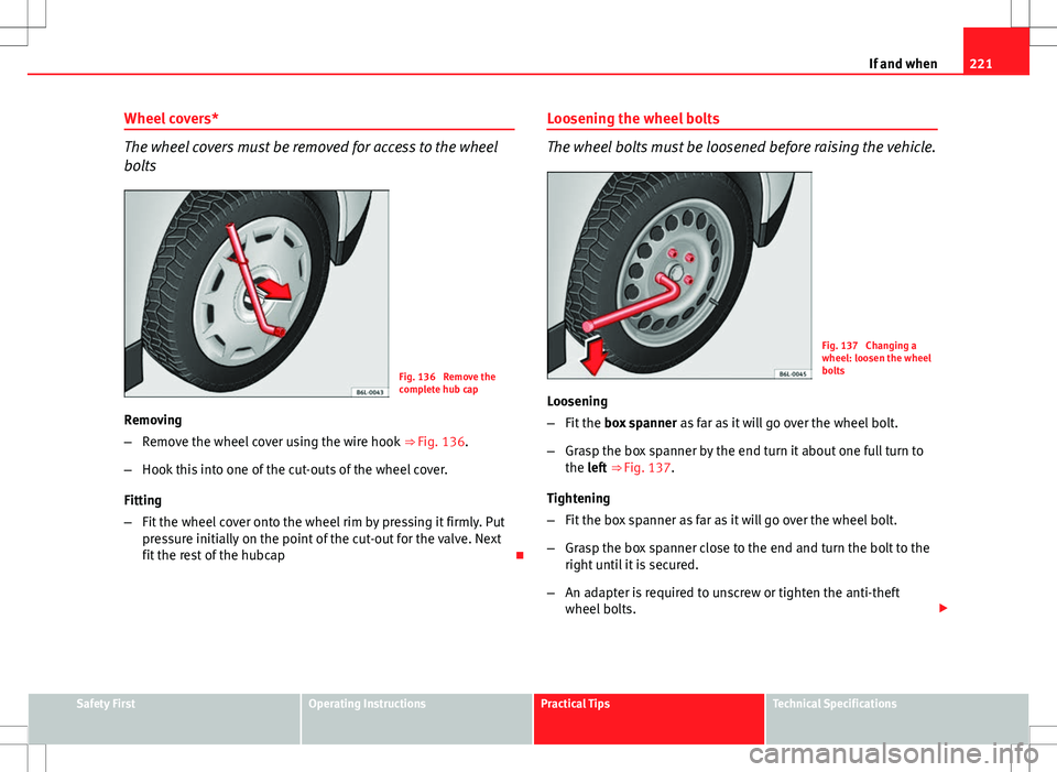
Fig. 136 Remove the
complete hub cap
Removing
– Remove the wheel cover using the wire hook ⇒ Fig. 136.
– Hook this into one of the cut-outs of the wheel cover.
Fitting
– Fit the wheel cover onto the wheel rim by pressing it firmly. Put
pressure initially on the point of the cut-out for the valve. Next
fit the rest of the hubcap Loosening the wheel bolts
The wheel bolts must be loosened before raising the vehicle.
Fig. 137 Changing a
wheel: loosen the wheel
bolts
Loosening
– Fit the box spanner as far as it will go over the wheel bolt.
– Grasp the box spanner by the end turn it about one full turn to
the left ⇒ Fig. 137.
Tightening
– Fit the box spanner as far as it will go over the wheel bolt.
– Grasp the box spanner close to the end and turn the bolt to the
right until it is secured.
– An adapter is required to unscrew or tighten the anti-theft
wheel bolts.
Safety FirstOperating InstructionsPractical TipsTechnical Specifications
Page 224 of 280
222If and when
WARNING
Loosen the wheel bolts only about one turn before raising the vehicle
with the jack, otherwise there is a risk of accident.
Note
● If the wheel bolt is very tight, you may be able to loosen it by pushing
down the end of the spanner carefully with your foot. Hold on to the vehicle
for support and take care not to slip.
Raising the vehicle
In order to remove the wheel, the vehicle must be raised
with a jack.
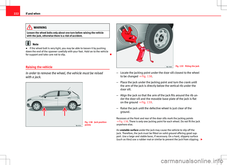
Fig. 138 Jack position
points
Fig. 139 Fitting the jack
– Locate the jacking point under the door sill closest to the wheel
to be changed ⇒ Fig. 138.
– Place the jack under the jacking point and turn the crank until
the arm of the jack is directly below the vertical rib under the
door sill.
– Align the jack so that the arm of the jack fits around the rib un-
der the door sill and the movable base plate of the jack is flat
on the ground ⇒ Fig. 139.
– Raise the jack until the defective wheel is just clear of the
ground.
Recesses at the front and rear of the door sills mark the jacking points
⇒ Fig. 138. There is only one jacking point for each wheel. Do not fit the jack
anywhere else.
An unstable surface under the jack may cause the vehicle to slip off the
jack. Therefore, the jack must be fitted on solid ground offering good sup-
port. Use a large and stable base, if necessary. On a hard, slippery surface
(such as tiles) use a rubber mat or similar to prevent the jack from slipping.
Page 225 of 280
223
If and when
WARNING
● Take all precautions so that the base of the jack does not slip. Failure
to do so could result in an accident.
● The vehicle can be damaged if the jack is not applied at the correct
jacking points. There is also a risk of injury since the jack can slip off
suddenly if it is not properly engaged.
Removing and fitting the wheel
For removal and fitting the wheel, the following tasks must
be completed.
Change the wheel as described below after loosening the wheel
bolts and raising the vehicle with the jack.
Removing a wheel
– Unscrew the wheel bolts using the box spanner and place them
on a clean surface.
Fitting a wheel
– Screw on the wheel bolts in position and tighten them loosely
with a box spanner.
The wheel bolts should be clean and easily screwed. Before fitting the spare
wheel, inspect the wheel condition and hub mounting surfaces. These sur-
faces must be clean before fitting the wheel.
If tyres with a specific direction of rotation are fitted, note the direction of
rotation. Anti-theft wheel bolts*
A special adapter is required to turn the anti-theft wheel
bolts. This is found in the tool box.
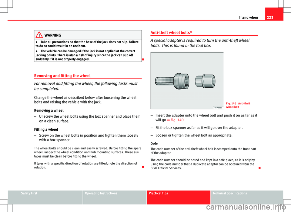
Fig. 140 Anti-theft
wheel bolt
– Insert the adapter onto the wheel bolt and push it on as far as it
will go ⇒ Fig. 140.
– Fit the box spanner as far as it will go over the adapter.
– Loosen or tighten the wheel bolt as appropriate.
Code
The code number of the anti-theft wheel bolt is stamped onto the front part
of the adaptor.
The code number should be noted and kept in a safe place, as it is only by
using the code number that a duplicate adaptor can be obtained from the
SEAT Official Services.
Safety FirstOperating InstructionsPractical TipsTechnical Specifications
Page 226 of 280
224If and when
Tyres with directional tread pattern
Tyres with directional tread pattern must be fitted so that
they rotate in the correct direction.
A directional tread pattern can be identified by arrows on the sidewall that
point in the direction of rotation. Always note the direction of rotation indi-
cated when fitting the wheel. This is important so that these tyres can give
maximum grip and avoid excessive noise, tread wear and aquaplaning.
If, in an emergency, you have to mount the spare wheel so it rotates in the
wrong direction, you must drive extremely carefully. The tyre will not give
optimum performance. This is particularly important when driving on wet
roads.
To benefit from the advantages of tyres with this type of tread pattern, the
defective tyre should be replaced as soon as possible so that all tyres again
rotate in the correct direction.
Tyre repair kit* (Tyre Mobility-System) General information and safety notes
Your vehicle is equipped with a tyre repair kit: the Tyre Mobility System.
In the event of a tyre puncture, a sealing product and an air compressor are
located in the luggage compartment under the floor panel.
The Tyre Mobility System will reliably seal punctures caused by the penetra-
tion of a foreign body of up to about 4 mm in diameter.
It is not necessary to remove the foreign body from the tyre.
Instructions for the sealing product are located on the sealing product con-
tainer. It also contains the instructions for using the compressor.
WARNING
● Do not attempt to repair a puncture with the sealing product if the
tyre has been damaged by driving the vehicle after the tyre has lost its
air.
● Always observe warnings and follow safety instructions concerning
compressor and sealing compound carefully.
● Do not drive faster than 80 km/h (50 mph), avoid heavy acceleration,
hard braking and fast cornering.
● Tyres which have been repaired with sealing compound are only suit-
able for temporary use over a short period. Therefore, please drive care-
fully to the next available specialised workshop.
For the sake of the environment
If you have to dispose of a sealant can, go to a specialised waste service or
to a SEAT Technical Service, where the product can be recycled in an appro-
priate waste container.
Note
● If sealing product should leak out, leave it to dry. This way you can pull it
off like a piece of foil.
● Observe the expiry date stated on the sealing compound can. Have the
sealing compound exchanged by a specialised workshop.
● Seek professional assistance if the repair of a tyre puncture is not possi-
ble with the sealing product.
Page 227 of 280
225
If and when
What to do first
Certain steps must be taken before repairing a tyre.
– If you have a flat tyre or puncture, park the vehicle as far away
from the flow of traffic as possible.
– Apply the handbrake firmly.
– Engage first gear , or put the selector lever to position P.
– All occupants should leave the vehicle. They should wait in a
safe area (for instance behind the roadside crash barrier).
– Check whether a repair is possible using the Tyre Mobility Sys-
tem “General information and safety notes.”
– Unscrew inflation cap from the affected wheel.
– Take the tyre repair kit out of the luggage compartment.
WARNING
Switch on the hazard warning lights and place the warning triangles in
position. This is for your own safety and also warns other road users.
CAUTION
Take special care if you have to repair a tyre on a slope.
Note
● Please observe legal requirements when doing so.
● Remember to replace the sealing product as soon as possible. Tyre repair
The following sections describe the procedures for repairing
a tyre.
Using the sealing product
– The instructions on the container give detailed information on
how to use the sealing product.
Inflating the tyre.
– Remove the air compressor and hose from the container.
– Screw the retaining nut onto the valve.
– Plug the compressor cable into a 12 volt power socket.
– Turn on compressor and monitor the pressure shown on the
pressure gauge.
Completing the repair
– Remove the compressor hose from the valve.
– Fit the valve cap.
– Unplug the compressor from the socket.
– Return all tools to their proper storing location.
Note
The compressor should never be allowed to run for longer than 6 minutes.
Safety FirstOperating InstructionsPractical TipsTechnical Specifications
Page 228 of 280
226If and when
Fuses
Changing a fuse
Blown fuses must be replaced
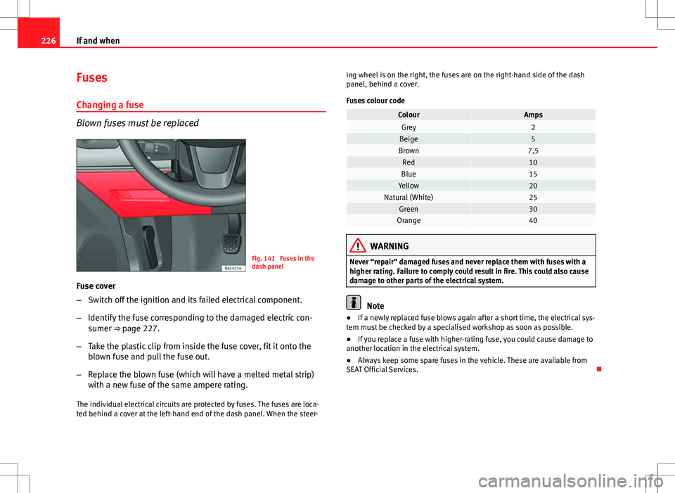
Fig. 141 Fuses in the
dash panel
Fuse cover
– Switch off the ignition and its failed electrical component.
– Identify the fuse corresponding to the damaged electric con-
sumer ⇒ page 227.
– Take the plastic clip from inside the fuse cover, fit it onto the
blown fuse and pull the fuse out.
– Replace the blown fuse (which will have a melted metal strip)
with a new fuse of the same ampere rating.
The individual electrical circuits are protected by fuses. The fuses are loca-
ted behind a cover at the left-hand end of the dash panel. When the steer- ing wheel is on the right, the fuses are on the right-hand side of the dash
panel, behind a cover.
Fuses colour code
ColourAmpsGrey2Beige5Brown7,5Red10Blue15Yellow20Natural (White)25Green30Orange40
WARNING
Never “repair” damaged fuses and never replace them with fuses with a
higher rating. Failure to comply could result in fire. This could also cause
damage to other parts of the electrical system.
Note
● If a newly replaced fuse blows again after a short time, the electrical sys-
tem must be checked by a specialised workshop as soon as possible.
● If you replace a fuse with higher-rating fuse, you could cause damage to
another location in the electrical system.
● Always keep some spare fuses in the vehicle. These are available from
SEAT Official Services.
Page 229 of 280
227
If and when
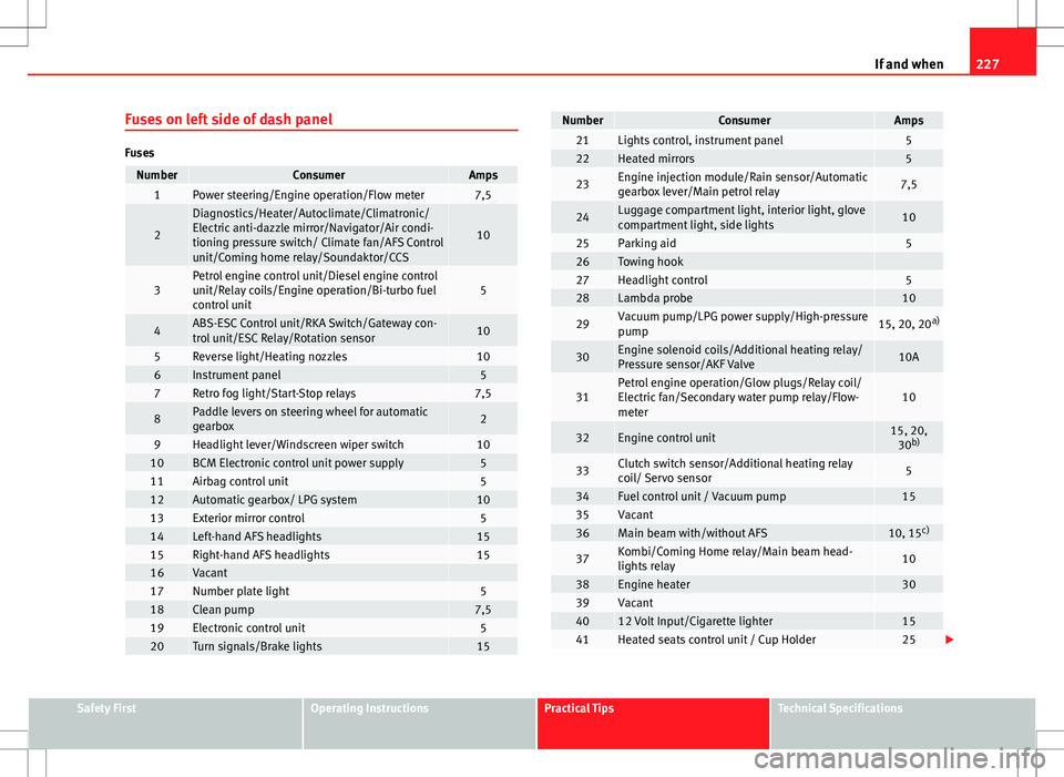
Fuses on left side of dash panel
Fuses
NumberConsumerAmps1Power steering/Engine operation/Flow meter7,5
2
Diagnostics/Heater/Autoclimate/Climatronic/
Electric anti-dazzle mirror/Navigator/Air condi-
tioning pressure switch/ Climate fan/AFS Control
unit/Coming home relay/Soundaktor/CCS
10
3Petrol engine control unit/Diesel engine control
unit/Relay coils/Engine operation/Bi-turbo fuel
control unit5
4ABS-ESC Control unit/RKA Switch/Gateway con-
trol unit/ESC Relay/Rotation sensor10
5Reverse light/Heating nozzles106Instrument panel57Retro fog light/Start-Stop relays7,5
8Paddle levers on steering wheel for automatic
gearbox2
9Headlight lever/Windscreen wiper switch1010BCM Electronic control unit power supply511Airbag control unit512Automatic gearbox/ LPG system1013Exterior mirror control514Left-hand AFS headlights1515Right-hand AFS headlights1516Vacant 17Number plate light518Clean pump7,519Electronic control unit520Turn signals/Brake lights15
NumberConsumerAmps21Lights control, instrument panel522Heated mirrors5
23Engine injection module/Rain sensor/Automatic
gearbox lever/Main petrol relay7,5
24Luggage compartment light, interior light, glove
compartment light, side lights10
25Parking aid526Towing hook 27Headlight control528Lambda probe10
29Vacuum pump/LPG power supply/High-pressure
pump15, 20, 20 a)
30Engine solenoid coils/Additional heating relay/
Pressure sensor/AKF Valve10A
31Petrol engine operation/Glow plugs/Relay coil/
Electric fan/Secondary water pump relay/Flow-
meter10
32Engine control unit15, 20,
30 b)
33Clutch switch sensor/Additional heating relay
coil/ Servo sensor5
34Fuel control unit / Vacuum pump1535Vacant 36Main beam with/without AFS10, 15 c)
37Kombi/Coming Home relay/Main beam head-
lights relay10
38Engine heater3039Vacant 4012 Volt Input/Cigarette lighter1541Heated seats control unit / Cup Holder25
Safety FirstOperating InstructionsPractical TipsTechnical Specifications
Page 230 of 280
228If and when
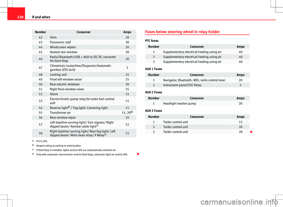
NumberConsumerAmps42Horn2043Panoramic roof3044Windscreen wipers2045Heated rear window30
46Radio/Bluetooth/USB + AUX-In/DC-DC converter
for Start-Stop20
47Climatronic/autoclima/Diagnosis/Automatic
gearbox (ZSS lock)5
48Locking unit2549Front left window raiser2550Rear electric windows3051Right front window raiser2552Alarm15
53Electro-kinetic pump relay/bi-turbo fuel control
unit15
54Reverse light d)
/ Fog light/ Cornering light1555Transformer on15, 20 b)56Rear window wiper10
57Left daytime running light/ Turn signals/ Right
dipped beam/ Number plate light c)15
58Right daytime running light/ Rear fog light/ Left
dipped beam/ Main bean relay/ X Relay c)15
a)
If it is LPG.
b) Ampere rating according to motorisation.
c) If Start-Stop is installed, lights and/or AFS are automatically switched on.
d) Only with automatic transmission and/or Start-Stop, automatic light-on and/or AFS. Fuses below steering wheel in relay holder
PTC fuses
NumberConsumerAmps1Supplementary electrical heating using air402Supplementary electrical heating using air403Supplementary electrical heating using air40
AUX 1 Fuses
NumberConsumerAmps1Navigator, Bluetooth, MDI, radio control lever202Instrument panel/ESC Relay5
AUX 2 Fuses
NumberConsumerAmps1Headlight washer pump20
AUX 3 Fuses
NumberConsumerAmps1Trailer control unit152Trailer control unit203Trailer control unit20