trailer Seat Ibiza ST 2012 User Guide
[x] Cancel search | Manufacturer: SEAT, Model Year: 2012, Model line: Ibiza ST, Model: Seat Ibiza ST 2012Pages: 282, PDF Size: 3.77 MB
Page 173 of 282
171
Intelligent technology
Electronic Stability Control (ESC)*
The ESC reduces the risk of skidding by braking the wheels individually.
The system uses the steering wheel angle and road speed to calculate the
changes of direction desired by the driver, and constantly compares them
with the actual behaviour of the vehicle. When irregularities occur, for exam-
ple, if the vehicle begins to skid, the ESC brakes the appropriate wheel au-
tomatically.
The forces acting on the braked wheel bring the vehicle back to a stable
condition. If the vehicle tends to oversteer, the system will act on the front
wheel on the outside of the turn.
WARNING
● Remember that not even the ESC can defy the laws of physics. This
should be kept in mind, particularly on slippery and wet roads and when
towing a trailer.
● Always adapt your driving style to suit the condition of the roads and
the traffic situation. The greater safety provided by the ESC should not
encourage you to run any risks.
CAUTION
● To ensure that the ESC works correctly, all four wheels must be fitted
with the same tyres. Any differences in the rolling radius of the tyres can
cause the system to reduce engine power when this is not desired.
● Any modifications made to the vehicle (for example, to the engine,
brake system, running gear or to the combination of wheels and tyres) may
affect the operation of the ABS, EDL, ESC and ASR. Anti-lock brake system (ABS)
The anti-lock brake system prevents the wheels locking during braking
⇒ page 169.
Electronic differential lock (EDL)*
The electronic differential lock helps prevent the loss of trac-
tion caused if one of the driven wheels starts spinning.
EDL helps the vehicle to start moving, accelerate and climb a gradient in
slippery conditions where this may otherwise be difficult or even impossi-
ble.
The system will control the revolutions of the driven wheels using the ABS
sensors (in case of an EDL fault the warning lamp for ABS lights up)
⇒ page 71.
At speeds of up to approximately 80 km/h (50 mph), it is able to balance
out differences in the speed of the driven wheels of approximately 100 rpm
caused by a slippery road surface on one side of the vehicle. It does this by
braking the wheel which has lost traction and distributing more driving
force to the other driven wheel via the differential.
To prevent the disc brake of the braking wheel from overheating, the EDL
cuts out automatically if subjected to excessive loads. The vehicle will con-
tinue to function normally without EDL. For this reason, the driver is not in-
formed that the EDL has been switched off.
The EDL will switch on again automatically when the brake has cooled
down.
Safety FirstOperating InstructionsPractical TipsTechnical Specifications
Page 175 of 282
173
Driving and the environment
Driving and the environment
Running-in Running in a new engine
The engine needs to be run in over the first 1500 km
(1000 miles).
Up to 1000 kilometres (600 miles)
– Do not drive at speeds of more than 2/3 the maximum speed.
– Do not accelerate hard.
– Avoid high engine revolutions.
– Do not tow a trailer.
From 1000 to 1500 kilometres (600 to 900 miles)
– Speeds can be gradually increased to the maximum road speed
or maximum permissible engine speed (rpm).
During its first few hours of running, the internal friction in the engine is
greater than later on, when all the moving parts have bedded in.
For the sake of the environment
If the engine is run in gently, its life will be increased and its oil consump-
tion reduced. Running in tyres and brake pads
New tyres should be run-in carefully for the first 500 km
(300 miles). New brake pads should be run-in carefully for
the first 200 km (120 miles).
During the first 200 km (120 miles), you can compensate for the reduced
braking effect by applying more pressure to the brake pedal. In case of a
sharp braking, the braking distance will be longer with new brake pads than
with brake pads which have been run-in.
WARNING
● At first, new tyres do not give maximum grip, and require running-in.
This may cause an accident. Drive particularly carefully in the first
500 km (300 miles).
● New brake pads must be “run in” and do not have the correct friction
properties during the first 200 km (120 miles). However, the reduced
braking capacity may be compensated by pressing on the brake pedal a
little harder.
Braking capacity and braking distance
The braking capacity and braking distance are influenced by
driving situations and road conditions.
The efficiency of the brakes depends directly on the brake pad wear. The
rate of wear of the brake pads depends to a great extent on the conditions
under which the vehicle is operated and the way the vehicle is driven. If you
often drive in town, drive short distances or have a sporty driving style, we
Safety FirstOperating InstructionsPractical TipsTechnical Specifications
Page 180 of 282
178Driving and the environment
●Reduction of volatile compounds in plastics
● CFC-free refrigerant in air conditioner
Compliance with prohibited materials regulation : cadmium, lead, mercury,
chrome VI.
Manufacturing methods
● Use of recycled material for manufacturing plastic parts
● Solvent-free cavity sealing
● Solvent-free wax for protecting the vehicles in transit
● Solvent-free adhesives
● No CFCs used in production
● Surplus materials used extensively for energy conversion and building
materials
● Overall water consumption reduced
● Heat recovery systems
● The use of water-soluble paints
Driving abroad Observations
To drive abroad, the following must be taken into consideration:
● For vehicles fitted with a catalytic converter ensure that unleaded petrol
is available for the journey. See the chapter “Refuelling”. Automobile organ-
isations will have information about service station networks selling unlea-
ded fuel.
● In some countries, it is possible that your vehicle model is not sold, and
therefore spare parts are not available or the Technical Services can only
carry out limited repairs. SEAT importers and distributors will gladly provide information about the
technical preparations that you vehicle requires and also about necessary
maintenance and repair possibilities.
Adhesive strips for headlights
If you have to drive a right-hand drive vehicle in a left-hand drive country, or
vice versa, the asymmetric dipped beam headlights will dazzle oncoming
traffic.
To prevent dazzling, you must apply stickers to certain parts of the head-
light lenses. Further information is available at your Technical Service.
In vehicles with adaptive headlights, the rotation system must previously be
disconnected. To do this, please go to a specialised workshop.
Trailer towing What do you need to bear in mind when towing a trailer?
Your vehicle may be used to tow a trailer when fitted with the correct equip-
ment.
If the vehicle is supplied with a factory-fitted towing bracket it will already
have the necessary technical modifications and meet the statutory require-
ments for towing a trailer. If you wish to retrofit a towing bracket, consult
⇒ page 192.
Connectors
Your vehicle is fitted with a 12-pin connector for the electrical connection
between the trailer and the vehicle.
Page 181 of 282
179
Driving and the environment
If the trailer has a 7-pin plug you will need to use an adapter cable. This is
available in any Technical Service.
Trailer weight/drawbar load
Never exceed the authorised trailer weight. If you do not load the trailer up
to the maximum permitted trailer weight, you can then climb correspond-
ingly steeper slopes.
The maximum trailer weights listed are only applicable for altitudes up to
1000 m above sea level. With increasing altitude the engine power and
therefore the vehicle climbing ability are impaired because of the reduced
air density. The maximum trailer weight has to be reduced accordingly. The
weight of the vehicle and trailer combination must be reduced by 10% for
every further 1000 m (or part thereof). The gross combination weight is the
actual weight of the laden vehicle plus the actual weight of the laden trailer.
When possible, operate the trailer with the maximum permitted drawbar
load on the ball joint of the towing bracket, but do not exceed the specified
limit.
The figures for trailer weights and drawbar loads that are given on the data
plate of the towing bracket are for certification purposes only. The correct
figures for your specific model, which may be lower than these figures for
the towing bracket, are given in the vehicle documentation or in ⇒ chap-
ter Technical Data.
Distributing the load
Distribute loads in the trailer so that heavy objects are as near to the axle as
possible. Loads carried in the trailer must be secured to prevent them mov-
ing.
Tyre pressure
Set tyre pressure to the maximum permissible pressure shown on the stick-
er on the inside of the fuel tank flap. Set the tyre pressure of the trailer tyres
in accordance with the trailer manufacturer's recommendations. Exterior mirrors
Check whether you can see enough of the road behind the trailer with the
standard rear vision mirrors. If this is not the case, you should have addi-
tional exterior mirrors fitted. Both exterior mirrors should be mounted on
hinged extension brackets. Adjust the mirrors to give sufficient vision to the
rear.
WARNING
Never transport people in a trailer. This could result in fatal accidents.
Note
● Towing a trailer places additional demands on the vehicle. We recom-
mend additional services between the normal inspection intervals if the ve-
hicle is used frequently for towing a trailer.
● Find out whether special regulations apply to towing a trailer in your
country.
Ball coupling of towing bracket*
The ball coupling is provided with instructions on fitting and removing the
ball coupling of the towing bracket.
WARNING
The towing bracket ball coupling must be stored securely in the luggage
compartment to prevent them being flung through the vehicle and caus-
ing injury.
Note
● By law, the ball coupling must be removed if a trailer is not being towed
if it obscures the number plate.
Safety FirstOperating InstructionsPractical TipsTechnical Specifications
Page 182 of 282
180Driving and the environment
Driving tips
Driving with a trailer always requires extra care.
Weight distribution
The weight distribution of a loaded trailer with an unladen vehicle is very
unfavourable. However, if this cannot be avoided, drive extra slowly to allow
for the unbalanced weight distribution.
Speed
The stability of the vehicle and trailer is reduced with increasing speed. For
this reason, it is advisable not to drive at the maximum permissible speed
in an unfavourable road, weather or wind conditions. This applies especially
when driving downhill.
You should always reduce speed immediately if the trailer shows the slight-
est sign of snaking. Never try to stop the “snaking” by increasing speed.
Always brake in due course. If the trailer has an overrun brake, apply the
brakes gently at first and then, firmly. This will prevent the jerking that can
be caused by locking of trailer wheels. Select a low gear in due course be-
fore going down a steep downhill. This enables you to use the engine brak-
ing to slow down the vehicle.
Reheating
At very high temperatures and during prolonged slopes, driving in a low
gear and high engine speed, always monitor the coolant temperature gauge
⇒ page 55.
Electronic Stability Control*
The ESC* system helps to stabilise the trailer in case of skidding or rocking.
Page 194 of 282
192Accessories, replacement of parts and modifications
Note
Please observe the operating instructions of your mobile telephone/two-
way radio.
Fitting a towing bracket*
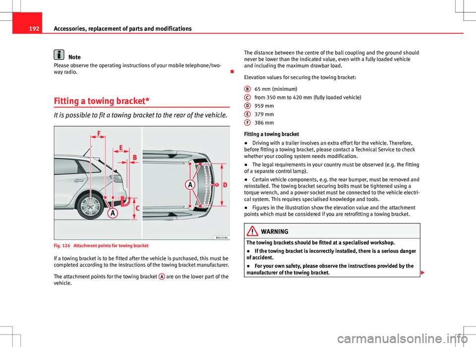
It is possible to fit a towing bracket to the rear of the vehicle.
Fig. 126 Attachment points for towing bracket If a towing bracket is to be fitted after the vehicle is purchased, this must be
completed according to the instructions of the towing bracket manufacturer.
The attachment points for the towing bracket A
are on the lower part of the
vehicle. The distance between the centre of the ball coupling and the ground should
never be lower than the indicated value, even with a fully loaded vehicle
and including the maximum drawbar load.
Elevation values for securing the towing bracket:
65 mm (minimum)
from 350 mm to 420 mm (fully loaded vehicle)
959 mm
379 mm
386 mm
Fitting a towing bracket
● Driving with a trailer involves an extra effort for the vehicle. Therefore,
before fitting a towing bracket, please contact a Technical Service to check
whether your cooling system needs modification.
● The legal requirements in your country must be observed (e.g. the fitting
of a separate control lamp).
● Certain vehicle components, e.g. the rear bumper, must be removed and
reinstalled. The towing bracket securing bolts must be tightened using a
torque wrench, and a power socket must be connected to the vehicle electri-
cal system. This requires specialised knowledge and tools.
● Figures in the illustration show the elevation value and the attachment
points which must be considered if you are retrofitting a towing bracket.
WARNING
The towing brackets should be fitted at a specialised workshop.
● If the towing bracket is incorrectly installed, there is a serious danger
of accident.
● For your own safety, please observe the instructions provided by the
manufacturer of the towing bracket.
BCDEF
Page 226 of 282
224If and when
If you have a puncture on one of the front wheels when using snow chains,
fit the compact temporary spare wheel in place of one of the rear wheels.
You can then attach the snow chains to the wheel taken from the rear and
use this wheel to replace the punctured front wheel.
WARNING
● The tyre pressures must be checked and corrected as soon as possi-
ble after fitting the temporary spare wheel.
● Do not drive faster than 80 km/h (50 mph). Higher speeds can cause
an accident.
● Avoid heavy acceleration, hard braking and fast cornering. Risk of ac-
cident.
● Never use more than one temporary spare wheel at the same time,
risk of accident.
● No other type of tyre (normal summer or winter tyre) may be fitted on
the compact temporary spare wheel rim.
Tyre repair kit*
The tyre repair kit (for vehicles not including a temporary
spare wheel) is stored under the floor panel in the luggage
compartment. Your vehicle is equipped with the Tyre Mobility System “Tyre repair kit”.
The tyre repair kit consists of a container with sealing product to repair the
puncture and a compressor to generate the required tyre pressure. The kit
will reliably seal punctures up to a size of about 4 mm caused by the pene-
tration of a foreign body into the tyre.
Note
● Seek professional assistance if the repair of a tyre puncture is not possi-
ble with the sealing product.
Wheel change Preparation work
What you must do before changing a wheel.
– If you have a flat tyre or puncture, park the vehicle as far away
from the flow of traffic as possible. Choose a location that is as
level as possible.
– All vehicle occupants should leave the vehicle. They should
wait in a safe area (for instance behind the roadside crash barri-
er).
– Switch the engine off. Switch the hazard warning lights on and
place the warning triangles in position.
– Apply the handbrake firmly.
– Engage the first gear , or put the selector lever to position P for
those vehicles with an automatic gearbox.
– If you are towing a trailer, unhitch it from your vehicle.
– Take the vehicle tools and the spare wheel out of the luggage
compartment.
Page 235 of 282
233
If and when
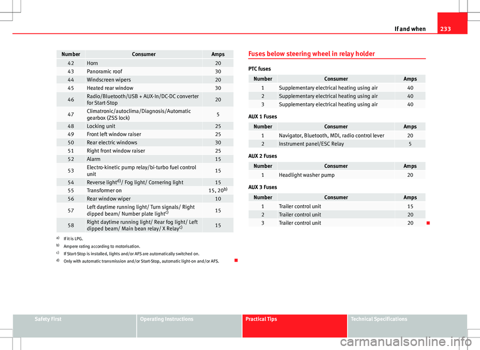
NumberConsumerAmps42Horn2043Panoramic roof3044Windscreen wipers2045Heated rear window30
46Radio/Bluetooth/USB + AUX-In/DC-DC converter
for Start-Stop20
47Climatronic/autoclima/Diagnosis/Automatic
gearbox (ZSS lock)5
48Locking unit2549Front left window raiser2550Rear electric windows3051Right front window raiser2552Alarm15
53Electro-kinetic pump relay/bi-turbo fuel control
unit15
54Reverse light d)
/ Fog light/ Cornering light1555Transformer on15, 20 b)56Rear window wiper10
57Left daytime running light/ Turn signals/ Right
dipped beam/ Number plate light c)15
58Right daytime running light/ Rear fog light/ Left
dipped beam/ Main bean relay/ X Relay c)15
a)
If it is LPG.
b) Ampere rating according to motorisation.
c) If Start-Stop is installed, lights and/or AFS are automatically switched on.
d) Only with automatic transmission and/or Start-Stop, automatic light-on and/or AFS. Fuses below steering wheel in relay holder
PTC fuses
NumberConsumerAmps1Supplementary electrical heating using air402Supplementary electrical heating using air403Supplementary electrical heating using air40
AUX 1 Fuses
NumberConsumerAmps1Navigator, Bluetooth, MDI, radio control lever202Instrument panel/ESC Relay5
AUX 2 Fuses
NumberConsumerAmps1Headlight washer pump20
AUX 3 Fuses
NumberConsumerAmps1Trailer control unit152Trailer control unit203Trailer control unit20
Safety FirstOperating InstructionsPractical TipsTechnical Specifications
Page 259 of 282
257
Description of specifications
Information on fuel consumption
Fuel consumption
The consumption and emission details shown on the vehicle
data sticker differ from one vehicle to another. The vehicle fuel consumption and CO 2 emissions can be consulted on the
vehicle data sticker in the spare wheel well, inside the luggage compart-
ment and on the rear cover of the Maintenance Programme.
The fuel consumption and CO 2 emission values refer to the weight category
assigned to your vehicle according to the engine and gearbox combination,
as well as the specific equipment fitted, and is only used to compare be-
tween the different models.
The fuel consumption and CO 2 emissions do not depend only on the per-
formance of the vehicle, they can also differ from the established values de-
pending on other factors such as driving style, road conditions, traffic con-
ditions, environmental conditions, load and number of passengers.
Calculation of fuel consumption
The consumption values have been calculated based on measurements per-
formed or supervised by certified CE laboratories according to the latest ver-
sion of directives 715/2007/EC and 80/1268/CEE (for more information
consult the European Union Publications Office at EUR-Lex: © European Un-
ion, http://eur-lex.europa.eu/en/index.htm) and are valid for the kerb
weight indicated for the vehicle.
Note
In practice, and considering all the factors mentioned here, consumption
values can differ from those calculated in the current European regulations. Weights
Kerb weight refers to the basic model with a fuel tank filled to 90% capacity
and without optional extras. The figure quoted includes 75 kg to allow for
the weight of the driver.
For special versions and optional equipment fittings or for the addition of
accessories, the weight of the vehicle will increase
⇒
.
WARNING
● Please note that the centre of gravity may shift when transporting
heavy objects; this may affect vehicle handling and lead to an accident.
Always adjust your speed and driving style to suit road conditions and re-
quirements.
● Never exceed the gross axle weight rating or the gross vehicle weight
rating. If the allowed axle load or the allowed total weight is exceeded,
the driving characteristics of the vehicle may change, leading to acci-
dents, injuries and damage to the vehicle.
Towing a trailer Trailer weights
Trailer weight
The trailer weights and drawbar loads approved are selected in intensive tri-
als according to precisely defined criteria. The approved trailer weights are
valid for vehicles in the EU for maximum speeds of 80 km/h (50 mph) (in
certain circumstances up to 100 km/h (60 mph)). The figures may be differ-
ent in other countries. All data in the official vehicle documentation takes
precedence over these data at all times ⇒
.
Safety FirstOperating InstructionsPractical TipsTechnical Specifications
Page 260 of 282
258Description of specifications
Drawbar loads
The maximum permitted drawbar load on the ball joint of the towing bracket
must not exceed 75 kg.
In the interest of road safety, we recommend that you always tow approach-
ing the maximum drawbar load. The response of the trailer on the road will
be poor if the drawbar load is too small.
If the maximum permissible drawbar load cannot be met (e.g. with small,
empty and light-weight single axle trailers or tandem axle trailers with a
wheelbase of less than 1 metre), a minimum of 4% of the actual trailer
weight is legally required for the drawbar load.
WARNING
● For safety reasons, do not exceed the 80 km/h (50 mph) limit. This is
also valid in countries where higher speeds are permitted.
● Never exceed the maximum trailer weights or the drawbar load. If the
permissible axle load or the permissible total weight is exceeded, the
driving characteristics of the vehicle may change, leading to accidents,
injuries and damage to the vehicle.
Wheels
Tyre pressure, snow chains, wheel bolts
Tyre pressures
The sticker with the tyre pressure values can be found on the inside of the
fuel tank flap. The tyre pressure values given there are for cold tyres. The
slightly raised pressures of warm tyres must not be reduced. ⇒
Snow chains
Snow chains may be fitted only to the front wheels, and only for the follow-
ing tyres:
175/70R14
185/60R15Chains with links not exceeding 15 mm (including the chain
closure)
215/45R16Chains with links not exceeding 9 mm (including the chain
closure)
215/40R17Chains with links not exceeding 7 mm (including the chain
closure)
Wheel bolts
After the wheels have been changed, the tightening torque of the wheel
bolts should be checked as soon as possible with a torque wrench ⇒
.
The tightening torque for steel and alloy wheels is 120 Nm.
WARNING
● Check the tyre pressure at least once per month. Checking the tyre
pressure is very important. If the tyre pressure is too high or too low,
there is an increased danger of accidents, particularly at high speeds.
● If the tightening torque of the wheel bolts is too low, they could loos-
en while the vehicle is in motion. Risk of accident! If the tightening tor-
que is too high, the wheel bolts and threads can be damaged.
Note
We recommend that you ask your Technical Service for information about
appropriate wheel, tyre and snow chain size.