brake light Seat Ibiza ST 2016 User Guide
[x] Cancel search | Manufacturer: SEAT, Model Year: 2016, Model line: Ibiza ST, Model: Seat Ibiza ST 2016Pages: 252, PDF Size: 5.56 MB
Page 91 of 252
Fuses and bulbs
Changing the tail light bulbs S umm
ary
of LED tail lights3 Applies to the model: IBIZA/IBIZA SC
LED
● Brak e lights
● Side lights
B
ulb
s
● Retro fog light
● Reverse lights
● Turn signal
Tail light summary 3 Applies to the model: IBIZA ST
T ai
l lights on side panel Bulb lamps
● Brake lights
● Side lights
● Turn signal
Lights on the r e
ar lid Bulb lamps
● Reverse lights
● Side lights
● Fog lights Tail lights on side panel LED lamps
●
Brake light (LED)
● Side light (LED)
● Turn signal
Lights on the re
ar lid LED lamps
● Reverse lights
● Side light (LED)
● Fog lights
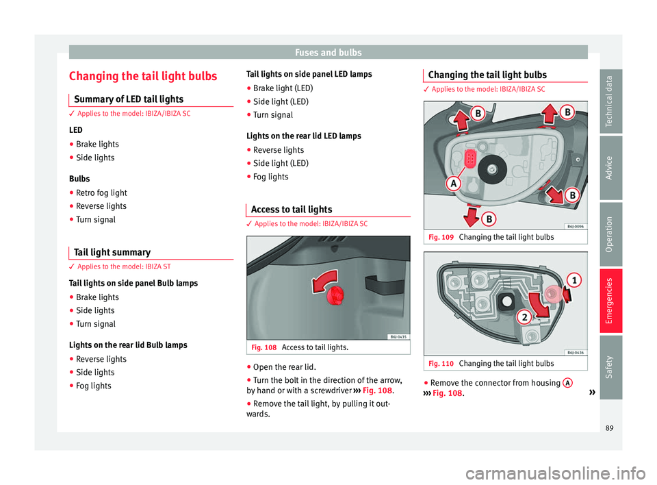
Access to tail lights 3 Applies to the model: IBIZA/IBIZA SC
Fig. 108
Access to tail lights. ●
Open the rear lid.
● Turn the bolt in the direction of the arrow,
b y
h and or w
ith a screwdriver ››› Fig. 108.
● Remove the tail light, by pulling it out-
wards. Ch
anging the tail light bulbs 3 Applies to the model: IBIZA/IBIZA SC
Fig. 109
Changing the tail light bulbs Fig. 110
Changing the tail light bulbs ●
Remove the connector from housing A ›››
Fig. 108. »
89
Technical data
Advice
Operation
Emergencies
Safety
Page 92 of 252
Emergencies
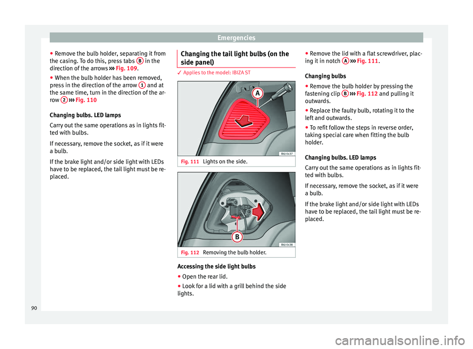
● Remo
ve the b
ulb holder, separating it from
the casing. To do this, press tabs B in the
dir ection of
the arro
ws ››› Fig. 109.
● When the bulb holder has been removed,
press
in the direction of the arrow 1 and at
the s ame time, t
urn in the dir ection of
the ar-
row 2
› ››
Fig. 110
Ch angin
g bulbs. LED lamps
Carry out the same operations as in lights fit-
ted with bulbs.
If necessary, remove the socket, as if it were
a bulb.
If the brake light and/or side light with LEDs
have to be replaced, the tail light must be re-
placed. Changing the tail light bulbs (on the
side panel) 3 Applies to the model: IBIZA ST
Fig. 111
Lights on the side. Fig. 112
Removing the bulb holder. Accessing the side light bulbs
● Open the rear lid.
● Look for a lid with a grill behind the side
lights. ●
Remo
ve the lid w
ith a flat screwdriver, plac-
ing it in notch A
› ››
Fig. 111
.
Ch an
ging bulbs
● Remove the bulb holder by pressing the
fast
ening clip B
› ››
Fig. 112
and pu
lling it
outwards.
● Replace the faulty bulb, rotating it to the
left and outw
ards.
● To refit follow the steps in reverse order,
taking s
pecial care when fitting the bulb
holder.
Changing bulbs. LED lamps
Carry out the same operations as in lights fit-
ted with bulbs.
If necessary, remove the socket, as if it were
a bulb.
If the brake light and/or side light with LEDs
have to be replaced, the tail light must be re-
placed.
90
Page 93 of 252
Fuses and bulbs
Changing the tail light bulbs (on the
r e
ar lid) 3 Applies to the model: IBIZA ST
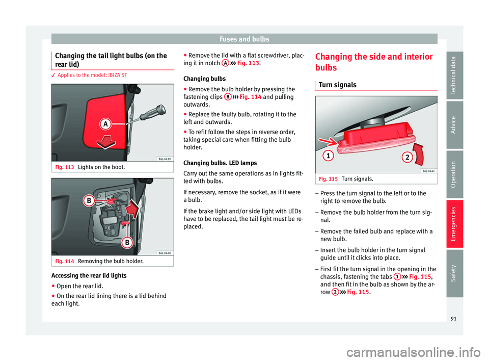
Fig. 113
Lights on the boot. Fig. 114
Removing the bulb holder. Accessing the rear lid lights
● Open the rear lid.
● On the rear lid lining there is a lid behind
e ac
h light . ●
R emove the lid w
ith a flat screwdriver, plac-
ing it in notch A
› ››
Fig. 113
.
Ch an
ging bulbs
● Remove the bulb holder by pressing the
fast
ening clips B
› ››
Fig. 114
and pu
lling
outwards.
● Replace the faulty bulb, rotating it to the
left and outw
ards.
● To refit follow the steps in reverse order,
taking s
pecial care when fitting the bulb
holder.
Changing bulbs. LED lamps
Carry out the same operations as in lights fit-
ted with bulbs.
If necessary, remove the socket, as if it were
a bulb.
If the brake light and/or side light with LEDs
have to be replaced, the tail light must be re-
placed. Changing the side and interior
bulb
s
Turn signals Fig. 115
Turn signals. –
Press the turn signal to the left or to the
right t
o r emo
ve the bulb.
– Remove the bulb holder from the turn sig-
nal.
– Remo
ve the failed bulb and replace with a
new bulb
.
– Insert the bulb holder in the turn signal
guide until it
clicks into place.
– First fit the turn signal in the opening in the
chas
sis, fastening the tabs 1
› ›
› Fig. 115 ,
and then fit
in the bulb as shown by the ar-
row 2
› ›
› Fig. 115 .
91
Technical data
Advice
Operation
Emergencies
Safety
Page 94 of 252
Emergencies
Number plate light 3 Applies to the model: IBIZA/IBIZA SC
– Inser t
the flat part of a screwdriver into the
special
slot and remove the bulb.
– Remove the bulb holder, by turning it until
it is fr
ee.
– Change the bulb.
– Replace the bulb holder, by turning it until
it fits fu
lly.
– Fit the light into the space and press until
you hear a “c lic
k”.
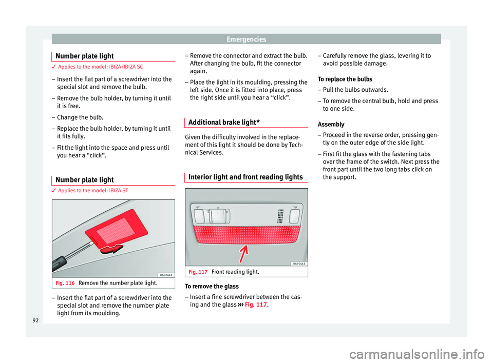
Number plate light 3 Applies to the model: IBIZA ST
Fig. 116
Remove the number plate light. –
Insert the flat part of a screwdriver into the
spec
ial
slot and remove the number plate
light from its moulding. –
Remove the c
onnector and extract the bulb.
After changing the bulb, fit the connector
again.
– Place the light in its moulding, pressing the
left s
ide. Once it is fitted into place, press
the right side until you hear a “click”.
Additional brake light* Given the difficulty involved in the replace-
ment of thi
s
light it should be done by Tech-
nical Services.
Interior light and front reading lights Fig. 117
Front reading light. To remove the glass
– Insert a fine screwdriver between the cas-
ing and the gl
as
s ››› Fig. 117. –
Carefu
lly remove the glass, levering it to
avoid possible damage.
To replace the bulbs
– Pull the bulbs outwards.
– To remove the central bulb, hold and press
to one side.
Assemb
ly
– Proceed in the reverse order, pressing gen-
tly on the outer edge of
the side light.
– First fit the glass with the fastening tabs
over the frame of
the switch. Next press the
front part until the two long tabs click on
the support.
92
Page 97 of 252
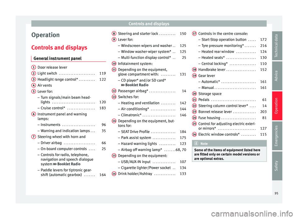
Controls and displays
Operation
C ontr
ol
s and displays
General instrument panel Door release lever
Light swit
c
h . . . . . . . . . . . . . . . . . . . . . . 119
Headlight range control* . . . . . . . . . .122
Air vents
Lever for:
– T
urn signals/main beam head-
lights . . . . . . . . . . . . . . . . . . . . . . . . . . 120
– Cruise c ontr
ol* . . . . . . . . . . . . . . . . . 183
Instrument panel and warning
lamps:
– Ins
truments . . . . . . . . . . . . . . . . . . . . 96
– Warning and indic ation l
amps . . . 35
Steering wheel with horn and – Driver airbag . . . . . . . . . . . . . . . . . . . 66
– On-board comp
uter controls . . . .25
– Control
s for radio, telephone,
navigation and speech dialogue
system ›››
Booklet Radio
– Paddle levers for tiptronic gear-
shift (automatic gearbox) . . . . . . .164
1 2
3
4
5
6
7 Steering and starter lock
. . . . . . . . . .150
Lever for: – Wind
sc
reen wipers and washer . .125
– Window wa
sher-wiper system* . .125
– Multi-fu
nction display control* . .25
Infotainment system:
Depending on the equipment,
glov
e compartment with: . . . . . . . . .131
– CD play
er* and/or SD card*
››› Booklet Radio
Passenger airbag* . . . . . . . . . . . . . . . . 14
Switches for:
– Heating and v
entilation . . . . . . . . . 142
– Air conditioning* . . . . . . . . . . . . . . . 144
– Clim
atronic* . . . . . . . . . . . . . . . . . . . . 146
D
epending on the equipment, but-
tons f
or:
– SEAT Drive Profile . . . . . . . . . . . . . . . 184
– Park a s
sist system . . . . . . . . . . . . . . 175
– Hazard warnin
g lights . . . . . . . . . . 123
– Airbag off warnin
g lamp* . . . . . . .68, 70
Depending on the equipment:
– USB/AUX-IN inp ut . . . . . . . . . . . . . . 107
– C
igar ett
e lighter/Power socket . .134
Drink holder/Ashtray . . . . . . . . . . . . .133
8 9
10
11
12
13
14
15
16 Controls in the centre console:
– St ar
t-
Stop operation button . . . . .172
– Tyre pr
essure monitoring* . . . . . . .216
– Heated re
ar window . . . . . . . . . . . . 124
– Heated seats* . . . . . . . . . . . . . . . . . . 130
– C
entral loc
king* . . . . . . . . . . . . . . . . 110
Handbrake lever . . . . . . . . . . . . . . . . . . 152
Gear lever – Automatic* . . . . . . . . . . . . . . . . . . . . . 161
– Manual . . . . . . . . . . . . . . . . . . . . . . . . . 161
St
orag
e space
Pedals . . . . . . . . . . . . . . . . . . . . . . . . . . . 61
St
eering column control lever* . . . .14
Bonnet release lever . . . . . . . . . . . . . .203
Fuse housing . . . . . . . . . . . . . . . . . . . . . 81
Control for adjusting electric exteri-
or mirrors* . . . . . . . . . . . . . . . . . . . . . . . 127
Electric
window controls* . . . . . . . . .115 Note
Some of the items of equipment listed here
are fitted on ly
on certain model versions or
are optional extras. 17
18
19
20
21
22
23
24
25
26
95
Technical data
Advice
Operation
Emergencies
Safety
Page 102 of 252
Operation
●
Additiona l
lights and other accessories in
front of the air inlet reduce the cooling effect
of the coolant. At high outside temperatures
and high engine loads, there is a risk of the
engine overheating.
● The front spoiler also ensures proper distri-
bution of the coo
ling air when the vehicle is
moving. If the spoiler is damaged this can re-
duce the cooling effect, which could cause
the engine to overheat. Seek specialist assis-
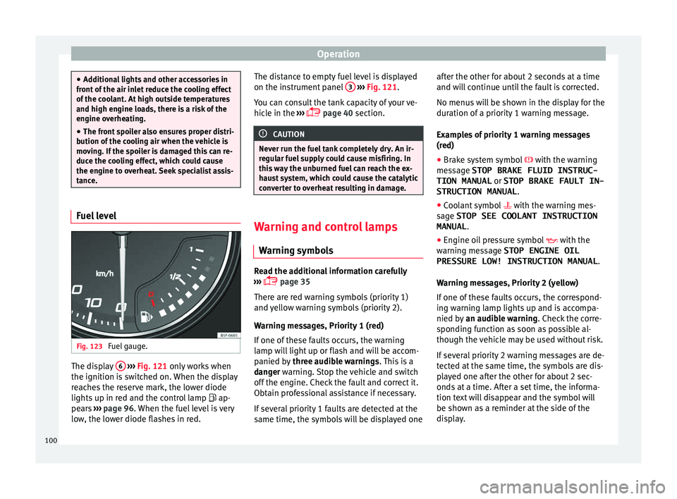
tance. Fuel level
Fig. 123
Fuel gauge. The display
6
› ›
› Fig. 121 on
ly works when
the ignition is switched on. When the display
reaches the reserve mark, the lower diode
lights up in red and the control lamp ap-
pears ››› page 96. When the fuel level is very
low, the lower diode flashes in red. The distance to empty fuel level is displayed
on the instrument p
anel 3
› ››
Fig. 121
.
Y ou c
an consult the tank capacity of your ve-
hicle in the ›››
page 40 section. CAUTION
Never run the fuel tank completely dry. An ir-
regu l
ar fuel supply could cause misfiring. In
this way the unburned fuel can reach the ex-
haust system, which could cause the catalytic
converter to overheat resulting in damage. Warning and control lamps
W arnin
g symbo l
s Read the additional information carefully
› ›
›
p
age 35
There are red warning symbols (priority 1)
and yellow warning symbols (priority 2).
Warning messages, Priority 1 (red)
If one of these faults occurs, the warning
lamp will light up or flash and will be accom-
panied by three audible warnings. This is a
danger warning. Stop the vehicle and switch
off the engine. Check the fault and correct it.
Obtain professional assistance if necessary.
If several priority 1 faults are detected at the
same time, the symbols will be displayed one after the other for about 2 seconds at a time
and will
continue until the fault is corrected.
No menus will be shown in the display for the
duration of a priority 1 warning message.
Examples of priority 1 warning messages
(red)
● Brake system symbol with the warning
me
ssage STOP BRAKE FLUID INSTRUC-
TION MANUAL or STOP BRAKE FAULT IN-
STRUCTION MANUAL .
● Coolant symbol with the warning me
s-
sage STOP SEE COOLANT INSTRUCTION
MANUAL .
● Engine oil pressure symbol with the
warning me
ssage STOP ENGINE OIL
PRESSURE LOW! INSTRUCTION MANUAL .
Warning messages, Priority 2 (yellow)
If one of these faults occurs, the correspond-
ing warning lamp lights up and is accompa-
nied by an audible warning. Check the corre-
sponding function as soon as possible al-
though the vehicle may be used without risk.
If several priority 2 warning messages are de-
tected at the same time, the symbols are dis-
played one after the other for about 2 sec-
onds at a time. After a set time, the informa-
tion text will disappear and the symbol will
be shown as a reminder at the side of the
display.
100
Page 125 of 252
Lights and visibility
The instrument lighting (needles) is switched
on when the ignition i s
on and the light i
s
off. The instrument lighting is dimmed auto-
matically as the daylight starts to fade. It
goes out completely when ambient light is
very low. This function is intended to remind
the driver to switch on the dipped beam
headlights in good time when light condi-
tions become poor.
Headlight range control
By using the electrical headlight range con-
trol you can adjust the headlight range to the
load level that is being carried in the vehicle
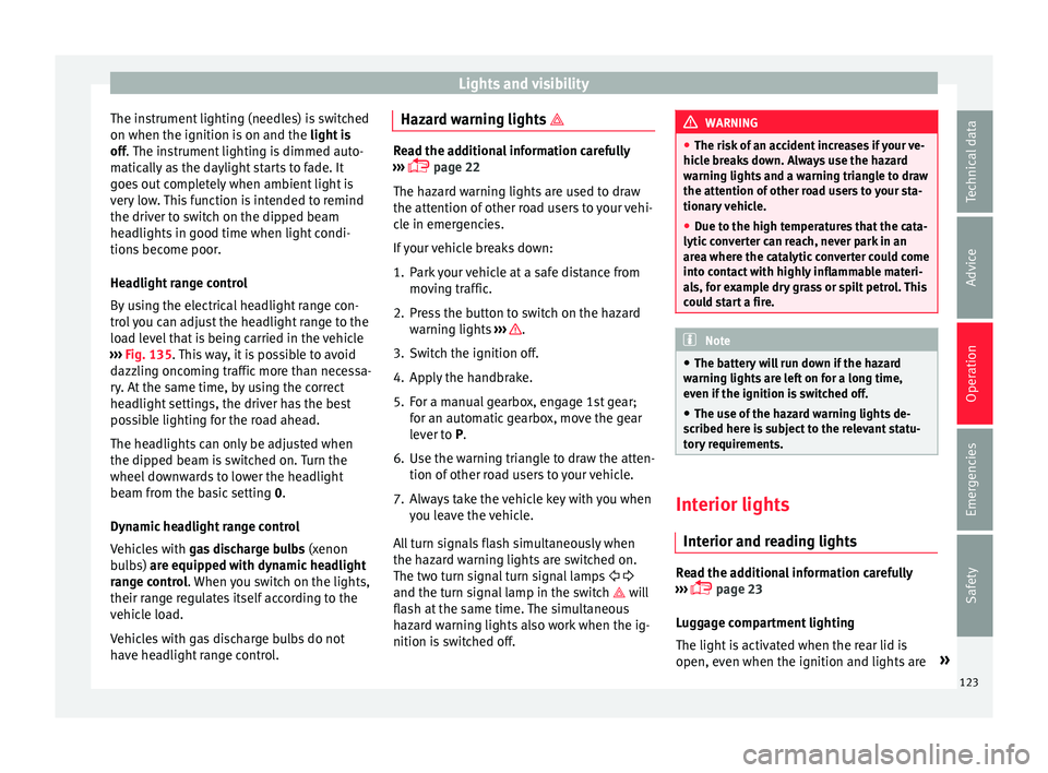
››› Fig. 135. This way, it is possible to avoid
dazzling oncoming traffic more than necessa-
ry. At the same time, by using the correct
headlight settings, the driver has the best
possible lighting for the road ahead.
The headlights can only be adjusted when
the dipped beam is switched on. Turn the
wheel downwards to lower the headlight
beam from the basic setting 0.
Dynamic headlight range control
Vehicles with gas discharge bulbs (xenon
bulbs) are equipped with dynamic headlight
range control. When you switch on the lights,
their range regulates itself according to the
vehicle load.
Vehicles with gas discharge bulbs do not
have headlight range control. Hazard warning lights
Read the additional information carefully
›››
p
age 22
The hazard warning lights are used to draw
the attention of other road users to your vehi-
cle in emergencies.
If your vehicle breaks down:
1. Park your vehicle at a safe distance from moving tr
affic.
2. Press the button to switch on the hazard warning lights ›
›› .
3. Switch the ignition off.
4. Apply the handbrake.
5. For a manual gearbox, engage 1st gear; for an aut
omatic
gearbox, move the gear
lever to P.
6. Use the warning triangle to draw the atten- tion of other roa
d users to your vehicle.
7. Always take the vehicle key with you when you leav
e the vehicle.
All turn signals flash simultaneously when
the hazard warning lights are switched on.
The two turn signal turn signal lamps
and the turn signal lamp in the switch will
flash at the same time. The simultaneous
hazard warning lights also work when the ig-
nition is switched off. WARNING
● The risk of an ac
cident increases if your ve-
hicle breaks down. Always use the hazard
warning lights and a warning triangle to draw
the attention of other road users to your sta-
tionary vehicle.
● Due to the high temperatures that the cata-
lytic conv
erter can reach, never park in an
area where the catalytic converter could come
into contact with highly inflammable materi-
als, for example dry grass or spilt petrol. This
could start a fire. Note
● The batter y
will run down if the hazard
warning lights are left on for a long time,
even if the ignition is switched off.
● The use of the hazard warning lights de-
scribed here i
s subject to the relevant statu-
tory requirements. Interior lights
Int erior and r
ea
ding lights Read the additional information carefully
› ›
›
p
age 23
Luggage compartment lighting
The light is activated when the rear lid is
open, even when the ignition and lights are »
123
Technical data
Advice
Operation
Emergencies
Safety
Page 155 of 252
Driving
of your brake pads checked by technical serv-
ic e
s mor
e frequently than recommended in
the Maintenance Programme.
If you drive with wet brakes, for example, af-
ter crossing areas of water, on days of heavy
rainfall or even after washing the car, the ef-
fect of the brakes is reduced as the brake
discs are wet or even frozen (in winter): in
this case, the brakes should be “dried” by
pressing the brake pedal several times. WARNING
Longer braking distances and faults in the
brake sy s
tem increase the risk of accidents.
● New brake pads must be run in and do not
have the corr
ect friction during the first
200 km. This reduced braking capacity may
be compensated for by pressing on the brake
pedal a little harder, which also applies when
the brake pads have to be changed further
on.
● If brakes are wet or frozen, or if you are
driving on ro
ads which have been salted,
braking power may be lower than normal.
● On steep slopes, if brakes are excessively
used, they wi
ll overheat. Before driving down
a long steep slope, it is advisable to reduce
speed and change down into a lower gear or
range (depending on the type of transmis-
sion). Thus, make use of engine braking and
relieve the brakes.
● Never let the brakes “drag” by applying
light pres
sure. Continuous braking will cause the brakes to overheat and the braking dis-
tance w
i
ll increase. Apply and then release
the brakes alternately.
● Never let the vehicle run with the engine
switched off
. The braking distance is in-
creased considerably when the brake servo is
not active.
● If the brake fluid loses its viscosity and is
subject
ed to heavy use, vapour bubbles can
form in the brake system. This reduces the ef-
ficiency of the brakes.
● Non-standard or damaged front spoilers
could r
estrict the airflow to the brakes and
cause them to overheat. Before purchasing
accessories please observe the relevant in-
structions ››› page 190, Modifications.
● If a brake system circuit fails, the braking
distanc
e will be increased considerably. Con-
tact a specialised workshop immediately and
avoid unnecessary journeys. Control lamp
Situations in which the warning lamp lights
up *
●
the brake fluid level is too low
› ›
›
p
age 209.
● there is a fault in the brake system.
This warnin
g lamp can light up together with
the ABS system warning lamp. WARNING
● If the brak e w
arning lamp does not go out
or if it lights up when driving, the brake fluid
level in the reservoir is too low so there is a
risk of an accident ››› page 209, Brake fluid.
Stop the vehicle and do not drive on. Obtain
technical assistance.
● If the brake warning lamp lights up to-
gether with the ABS
lamp this could be
due to an ABS fault. This could cause the rear
wheels to lock quickly when you brake. This
could cause the rear to break away. Risk of
skidding. Stop the vehicle and seek technical
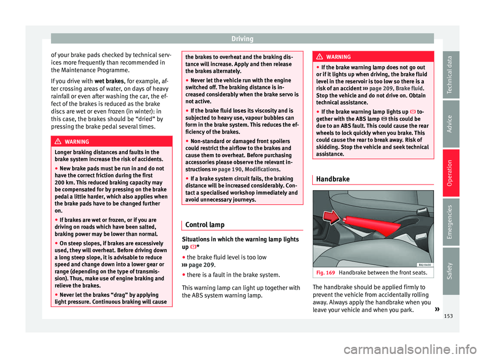
assistance. Handbrake
Fig. 169
Handbrake between the front seats. The handbrake should be applied firmly to
pr
ev
ent the
vehicle from accidentally rolling
away. Always apply the handbrake when you
leave your vehicle and when you park. »
153
Technical data
Advice
Operation
Emergencies
Safety
Page 156 of 252
Operation
Applying the handbrake
– Pull the handbrake lever up firmly
› ›
›
Fig. 169
.
Releasing the handbrake
– Pull the lever up slightly and press the re-
lease kno
b in the direction of the arrow
››› Fig. 169 and guide the handbrake lever
down fully ››› .
A lw
ay
s pull the handbrake all the way up, so
there is less risk of driving off with it still en-
gaged ››› .
The h andbr
ake w
arning lamp lights up
when the handbrake is applied and the igni-
tion switched on. The warning lamp turns off
when the handbrake is released. WARNING
● Never use the h andbr
ake to stop the vehi-
cle when it is in motion. The braking distance
is considerably longer, because braking is
only applied to the rear wheels. Risk of acci-
dent!
● If the handbrake is only partially released,
this wi
ll cause the rear brakes to overheat,
which can impair the function of the brake
system and could lead to an accident. This al-
so causes premature wear on the rear brake
pads. CAUTION
Always apply the handbrake before you leave
the vehic l
e. Put it in 1st gear as well. In vehi-
cles with an automatic gearbox, place the
gear lever in position P. Parking
The handbrake should always be firmly ap-
plied when the v
ehic
le is parked.
Always note the following points when park-
ing the vehicle: – Use the brake pedal to stop the vehicle.
– Apply the handbrake.
– Put it in 1st gear.
– Switch the engine off and remove the key
from the ignition. T urn the s
teering wheel
slightly to engage the steering lock.
– Always take you keys with you when you
leave the
vehicle ››› .
Ad dition
al
notes on parking the vehicle on
gradients:
Turn the steering wheel so that the vehicle
rolls against the kerb if it started to roll.
● If the vehicle is parked facing downhill
,
turn the front wheels so that they point to-
wards the kerb . ●
If the vehic
le is parked facing uphill, turn
the front wheels so that they point away from
the kerb.
● Secure the vehicle as usual by applying the
handbrake firm
ly and putting it in 1st gear. WARNING
● Take me a
sures to reduce the risk of injury
when you leave your vehicle unattended.
● Never park where the hot exhaust system
could ignit
e inflammable materials, such as
dry grass, low bushes, spilt fuel etc.
● Never allow vehicle occupants to remain in
the vehicl
e when it is locked. They would be
unable to open the vehicle from the inside,
and could become trapped in the vehicle in
an emergency. In the event of an emergency,
locked doors will delay assistance to vehicle
occupants.
● Never leave children alone in the vehicle.
They coul
d set the vehicle in motion, for ex-
ample, by releasing the handbrake or the
gearbox lever.
● Depending on weather conditions, it may
become extremely
hot or cold inside the vehi-
cle. This can be fatal. 154
Page 157 of 252
Driving
Braking and stability systems El ectr
onic
Stability Control (ESC)*This Electronic Stability System reduces the
risk of
sk
idding and improves the vehicle's
stability and ability to hold the road.
The Electronic Stability Control (ESC) contains
the electronic differential lock (EDL) and the
traction control system (ASR). The ESC works
together with the ABS. Both control lamps
will light up if the ESC or ABS systems are
faulty.
The ESC system is started automatically
when the engine is started.
The ESC system is always active and cannot
be switched off. With the Easy Connect sys-
tem it is only possible to deactivate the ASR
or else select Sport mode.
The ASR can be deactivated when wheel spin
is desirable ›››
page 156.
For example:
● When driving with snow chains.
● When driving in deep snow or on loose sur-
face s.
● When the
vehicle is stuck, to rock it back-
wards
and forwards.
Press the button to switch the ASR back on
when you no longer need wheel spin. Electronic Stability Control (ESC)*
The ESC reduc
es the risk of skidding by brak-
ing the wheels individually.
The system uses the steering wheel angle
and road speed to calculate the changes of
direction desired by the driver, and constant-
ly compares them with the actual behaviour
of the vehicle. When irregularities occur, for
example, if the vehicle begins to skid, the
ESC brakes the appropriate wheel automati-
cally.
The forces acting on the braked wheel bring
the vehicle back to a stable condition. If the
vehicle tends to oversteer (the rear end
slides out), the system will act on the front
wheel on the outside of the turn.
Control lamp
There are two control lamps for the electronic
stability control. The lamp provides infor-
mation concerning function and disconnec-
tion status.
Both control lamps light up together when
the ignition is switched on and should turn
off after approximately 2 seconds. This is the
time taken for the function check.
This programme includes the ABS, EDL and
ASR. It also includes emergency braking as-
sistance (BAS). The control lamp
has the f ollowing func-
tions:
● It flashes whilst driving when the ASR/ESC
is activat
ed.
● It will light up if there is a fault in the ESC.
● As the ESC operates in conjunction with the
ABS, the ESC light w
ill also come on if a fault
should occur in the ABS.
If the ESC control lamp lights up and stays
on after the engine is started, this may mean
that the control system has temporarily
switched off the ESC. In this case the ESC can
be reactivated by switching the ignition off
and then on again. If the control lamp goes
out, this means the system is fully functional.
The lamp provides information about the
disconnection status of the system:
● It stays lit when the ASR is disconnected on
press
ing the switch or if we select ESC
Sport mode, only by means of Easy Connect. WARNING
● Do not for g
et that the electronic stability
control ESC cannot defy the laws of physics.
This should be kept in mind, particularly on
slippery and wet roads and when towing a
trailer.
● Always adapt your driving style to suit the
condition of the ro
ads and the traffic situa-
tion. The greater safety provided by the ESC
should not encourage you to run any risks. » 155
Technical data
Advice
Operation
Emergencies
Safety