ESP Seat Leon 5D 2011 Owner's Guide
[x] Cancel search | Manufacturer: SEAT, Model Year: 2011, Model line: Leon 5D, Model: Seat Leon 5D 2011Pages: 302, PDF Size: 4.17 MB
Page 90 of 302
88Cockpit
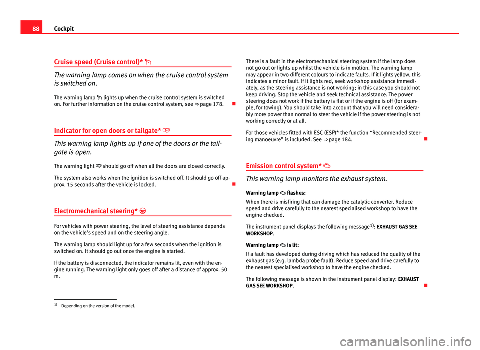
Cruise speed (Cruise control)*
The warning lamp comes on when the cruise control system
is switched on.
The warning lamp lights up when the cruise control system is switched
on. For further information on the cruise control system, see ⇒ page 178.
Indicator for open doors or tailgate*
This warning lamp lights up if one of the doors or the tail-
gate is open. The warning light should go off when all the doors are closed correctly.
The system also works when the ignition is switched off. It should go off ap-
prox. 15 seconds after the vehicle is locked.
Electromechanical steering*
For vehicles with power steering, the level of steering assistance depends
on the vehicle's speed and on the steering angle.
The warning lamp should light up for a few seconds when the ignition is
switched on. It should go out once the engine is started.
If the battery is disconnected, the indicator remains lit, even with the en-
gine running. The warning light only goes off after a distance of approx. 50
m. There is a fault in the electromechanical steering system if the lamp does
not go out or lights up whilst the vehicle is in motion. The warning lamp
may appear in two different colours to indicate faults. If it lights yellow, this
indicates a minor fault. If it lights red, seek workshop assistance immedi-
ately, as the steering assistance is not working; in this case you should not
keep driving. Stop the vehicle and seek technical assistance. The power
steering does not work if the battery is flat or if the engine is off (for exam-
ple, for towing). You should take into account that you will need considera-
bly more power than normal to steer the vehicle if the power steering is not
working correctly or at all.
For those vehicles fitted with ESC (ESP)* the function “Recommended steer-
ing manoeuvre” is included. See
⇒ page 184.
Emission control system*
This warning lamp monitors the exhaust system.
Warning lamp flashes:
When there is misfiring that can damage the catalytic converter. Reduce
speed and drive carefully to the nearest specialised workshop to have the
engine checked.
The instrument panel displays the following message 1)
: EXHAUST GAS SEE
WORKSHOP.
Warning lamp is lit:
If a fault has developed during driving which has reduced the quality of the
exhaust gas (e.g. lambda probe fault). Reduce speed and drive carefully to
the nearest specialised workshop to have the engine checked.
The following message is shown in the instrument panel display: EXHAUST
GAS SEE WORKSHOP .
1)
Depending on the version of the model.
Page 91 of 302

89
Cockpit
Electronic Stability Control ESC (ESP) * /
There are two control lamps for the electronic stability con-
trol. The lamp provides information concerning the func-
tion and the provides information on the disconnection
status
Both lamps come on together when the ignition is switched on and should
go out after approx. 2 seconds, which is how long the function check lasts.
This programme includes the ABS, EDL and ASR (TCS). This also includes
the brake assist system (BAS), automatic cleaning of the brake discs and
the trailer stability programme (TSP).
The warning lamp has the following functions: ● It flashes when the ASR (TCS)/ESC (ESP) is activated when driving.
● It will light up continuously if there is a malfunction in the ESC (ESP).
● The ESC (ESP) lamp will also come on if a fault should occur in the ABS
because the ESC (ESP) operates in conjunction with the ABS.
If the ESP warning lamp lights up and stays on after the engine is started,
this may mean that the control system has temporarily switched off the ESP.
In this case the ESC (ESP) can be reactivated by switching the ignition off
and then on again. If the warning lamp goes out, this means the system is
fully functional.
The lamp provides information about the disconnection status of the
system:
● It stays lit when the ASR (TCS) is disconnected after pressing the
switch. Differential lock fault (EDL)*EDL operates along with the ABS in vehicles equipped with
the Electronic Stability Control ESC (ESP)*
A malfunction in the EDL is indicated by the ABS warning lamp . Take the
vehicle to a specialised workshop as soon as possible. For further informa-
tion on the EDL see ⇒ page 185, Electronic differential lock (EDL)*.
Traction control system ASR (TCS)* /
The traction control system prevents the driven wheels from
spinning when the vehicle is accelerating
There are two warning lamps for the traction control system: and . Both
lamps come on together when the ignition is switched on and should go out
after approx. 2 seconds, which is how long the function check lasts.
The lamp has the following function:
● It flashes when the ASR (TCS) is activated while driving.
If the system is deactivated or if it has any fault, the warning lamp will re-
main lit. The ASR (TCS) lamp will also come on if a fault should occur in the
ABS because the ASR (TCS) operates in conjunction with the ABS. For fur-
ther information, see ⇒ page 182, Brakes
The lamp provides information about the disconnection status of the
system:
● It stays lit when the ASR (TCS) is disconnected after pressing the OFF
switch.
By pressing again, the ASR (TCS) function is reactivated and the warning
lamp switched off.
Safety FirstOperating InstructionsPractical TipsTechnical Specifications
Page 122 of 302
120Lights and visibility
Dynamic cornering lights (AFS)
The dynamic cornering lights only operate if the vehicle is travelling at more
than 10 km/h and the dipped headlights are on. When taking a bend, the
road is illuminated better with directional gas discharge bulbs than with
conventional fixed headlights.
A fault in the system is indicated via the flashing of the control lamp on
the instrument panel. At the same time, a text message with information or
instructions to perform necessary operations may appear on the instrument
panel display. Take the vehicle to a specialised workshop and have the fault
repaired.
If the control bulb lights up on the instrument panel but all the bulbs are
operating correctly ⇒ page 254, there may still be a fault in the dynamic
curve lighting system (AFS). Take the vehicle to a specialised workshop and
have the fault repaired.
WARNING
If the “automatic dipped beam control” is switched on, the dipped beam
headlights will not be switched on in fog. They should be switched on
manually using the light switch. The driver is personally responsible for
the correct use of lights in all situations. “Automatic headlight control”
is merely a system to support the driver. Where necessary, switch on the
lights manually using the light switch.
Fog lights with cornering function*
When the turn signal is switched on to turn or on very tight bends, the right
or left fog lamp automatically comes on to function as a cornering light. The
cornering light only operates if the dipped lights are on.
WARNING
If the “automatic dipped beam control” is switched on, the dipped beam
headlights will not be switched on in fog. They should be switched on
manually using the light switch. The driver is personally responsible for
the correct use of lights in all situations. “Automatic headlight control”
is merely a system to support the driver. Where necessary, switch on the
lights manually using the light switch.
Hazard warning lights
The hazard warning lights are used to draw the attention of
other road users to your vehicle in emergencies.
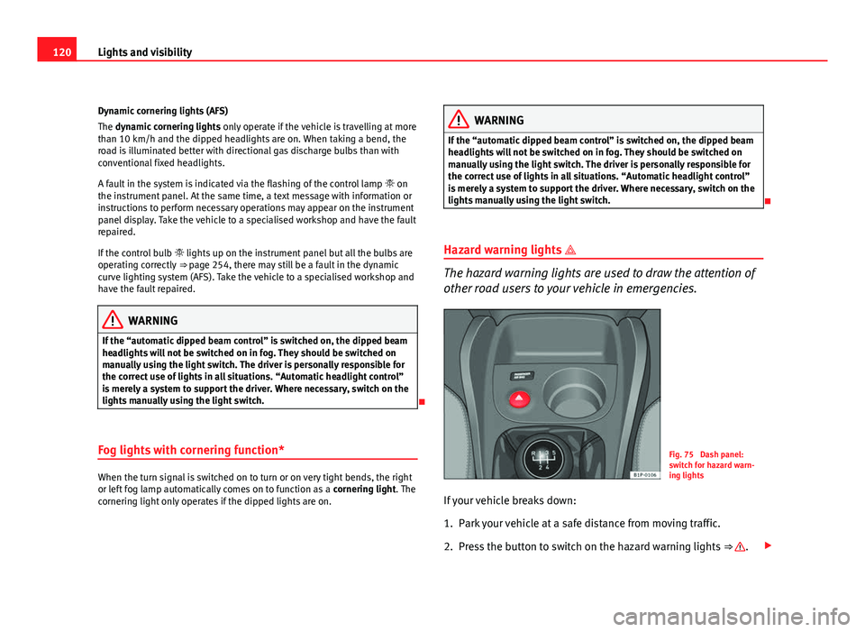
Fig. 75 Dash panel:
switch for hazard warn-
ing lights
If your vehicle breaks down:
1. Park your vehicle at a safe distance from moving traffic.
2. Press the button to switch on the hazard warning lights ⇒
.
Page 124 of 302
122Lights and visibility
Turn signal and main beam headlight lever
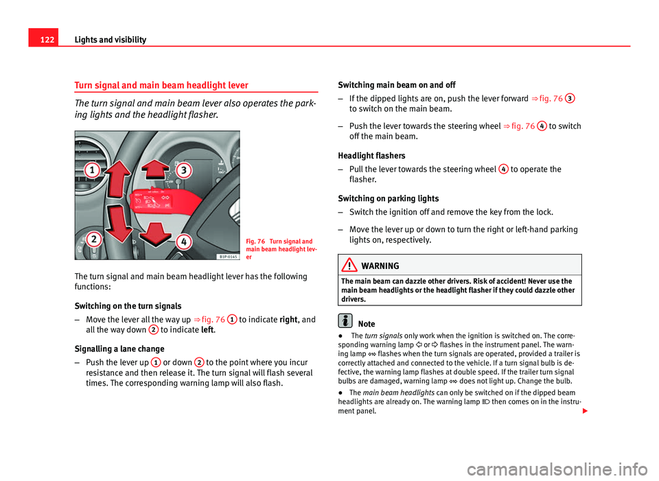
The turn signal and main beam lever also operates the park-
ing lights and the headlight flasher.
Fig. 76 Turn signal and
main beam headlight lev-
er
The turn signal and main beam headlight lever has the following
functions:
Switching on the turn signals
– Move the lever all the way up ⇒ fig. 76 1
to indicate right, and
all the way down 2 to indicate left.
Signalling a lane change
– Push the lever up 1
or down 2 to the point where you incur
resistance and then release it. The turn signal will flash several
times. The corresponding warning lamp will also flash. Switching main beam on and off
–
If the dipped lights are on, push the lever forward ⇒ fig. 76 3
to switch on the main beam.
– Push the lever towards the steering wheel ⇒ fig. 76 4
to switch
off the main beam.
Headlight flashers
– Pull the lever towards the steering wheel 4
to operate the
flasher.
Switching on parking lights
– Switch the ignition off and remove the key from the lock.
– Move the lever up or down to turn the right or left-hand parking
lights on, respectively.
WARNING
The main beam can dazzle other drivers. Risk of accident! Never use the
main beam headlights or the headlight flasher if they could dazzle other
drivers.
Note
● The turn signals only work when the ignition is switched on. The corre-
sponding warning lamp or flashes in the instrument panel. The warn-
ing lamp flashes when the turn signals are operated, provided a trailer is
correctly attached and connected to the vehicle. If a turn signal bulb is de-
fective, the warning lamp flashes at double speed. If the trailer turn signal
bulbs are damaged, warning lamp does not light up. Change the bulb.
● The main beam headlights can only be switched on if the dipped beam
headlights are already on. The warning lamp then comes on in the instru-
ment panel.
Page 125 of 302
123
Lights and visibility
● The headlight flasher comes on for as long as you pull the lever – even if
no other lights are switched on. The warning lamp then comes on in the
instrument panel.
● When the parking lights are switched on, the headlight and the tail light
on the corresponding side of the vehicle light up. The parking lights will on-
ly work if the key is removed from the ignition. If the lights are switched on,
an acoustic signal will be emitted while the driver door is open.
● If the turn signal lever is left on after the key has been taken out of the
ignition lock, an acoustic signal sounds when the driver door is opened.
This is a reminder to switch off the turn signal, unless of course you wish to
leave the parking light on.
Interior lights
Front interior light
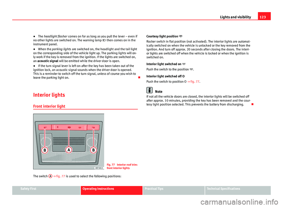
Fig. 77 Interior roof trim:
front interior lights
The switch A
⇒ fig. 77 is used to select the following positions: Courtesy light position
Rocker switch in flat position (not activated). The interior lights are automat-
ically switched on when the vehicle is unlocked or the key removed from the
ignition. And turn off approx. 20 seconds after closing the doors. The interi-
or lights are switched off when the vehicle is locked or when the ignition is
switched on.
Interior light switched on
Push the switch to the position .
Interior light switched off O
Push the switch to position O ⇒ fig. 77.
Note
If not all the vehicle doors are closed, the interior lights will be switched off
after approx. 10 minutes, providing the key has been removed and the cour-
tesy light position selected. This prevents the battery from discharging.
Safety FirstOperating InstructionsPractical TipsTechnical Specifications
Page 128 of 302
126Lights and visibility
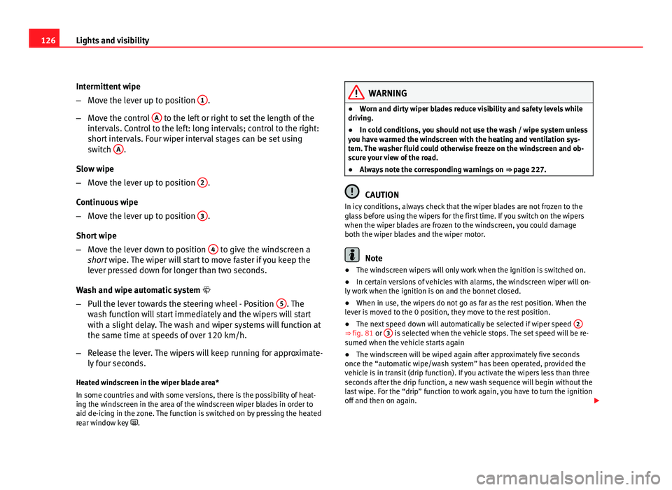
Intermittent wipe
–Move the lever up to position 1
.
– Move the control A
to the left or right to set the length of the
intervals. Control to the left: long intervals; control to the right:
short intervals. Four wiper interval stages can be set using
switch A
.
Slow wipe
– Move the lever up to position 2
.
Continuous wipe
– Move the lever up to position 3
.
Short wipe
– Move the lever down to position 4
to give the windscreen a
short wipe. The wiper will start to move faster if you keep the
lever pressed down for longer than two seconds.
Wash and wipe automatic system
– Pull the lever towards the steering wheel - Position 5
. The
wash function will start immediately and the wipers will start
with a slight delay. The wash and wiper systems will function at
the same time at speeds of over 120 km/h.
– Release the lever. The wipers will keep running for approximate-
ly four seconds.
Heated windscreen in the wiper blade area*
In some countries and with some versions, there is the possibility of heat-
ing the windscreen in the area of the windscreen wiper blades in order to
aid de-icing in the zone. The function is switched on by pressing the heated
rear window key .
WARNING
● Worn and dirty wiper blades reduce visibility and safety levels while
driving.
● In cold conditions, you should not use the wash / wipe system unless
you have warmed the windscreen with the heating and ventilation sys-
tem. The washer fluid could otherwise freeze on the windscreen and ob-
scure your view of the road.
● Always note the corresponding warnings on ⇒ page 227.
CAUTION
In icy conditions, always check that the wiper blades are not frozen to the
glass before using the wipers for the first time. If you switch on the wipers
when the wiper blades are frozen to the windscreen, you could damage
both the wiper blades and the wiper motor.
Note
● The windscreen wipers will only work when the ignition is switched on.
● In certain versions of vehicles with alarms, the windscreen wiper will on-
ly work when the ignition is on and the bonnet closed.
● When in use, the wipers do not go as far as the rest position. When the
lever is moved to the 0 position, they move to the rest position.
● The next speed down will automatically be selected if wiper speed 2
⇒ fig. 81 or 3 is selected when the vehicle stops. The set speed will be re-
sumed when the vehicle starts again
● The windscreen will be wiped again after approximately five seconds
once the “automatic wipe/wash system” has been operated, provided the
vehicle is in transit (drip function). If you activate the wipers less than three
seconds after the drip function, a new wash sequence will begin without the
last wipe. For the “drip” function to work again, you have to turn the ignition
off and then on again.
Page 130 of 302
128Lights and visibility
Rear window wiper
The windscreen wiper lever operates the windscreen wiper
and the wash and wipe system for the rear window.
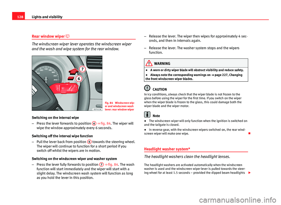
Fig. 84 Windscreen wip-
er and windscreen wash
lever: rear window wiper
Switching on the interval wipe
– Press the lever forwards to position 6
⇒ fig. 84. The wiper will
wipe the window approximately every 6 seconds.
Switching off the interval wipe function
– Pull the lever back from position 6
towards the steering wheel.
The wiper will continue to function for a short period if you
switch off whilst the wipers are in motion.
Switching on the windscreen wiper and washer system
– Press the lever fully forwards to position 7
⇒ fig. 84. The wash
function will start immediately and the wiper will start with a
slight delay. The windscreen wash system will function as long
as you hold the lever in this position. –
Release the lever. The wiper then wipes for approximately 4 sec-
onds, and then in intervals again.
– Release the lever. The washer system stops and the wipers
function.
WARNING
● A worn or dirty wiper blade will obstruct visibility and reduce safety.
● Always note the corresponding warnings on ⇒ page 227, Changing
the front windscreen wiper blades.
CAUTION
In icy conditions, always check that the wiper blade is not frozen to the
glass before using the wiper for the first time. If you switch on the wiper
when the wiper blade is frozen to the glass, this could damage both the
wiper blade and the wiper motor.
Note
● The windscreen wiper will only function when the ignition is switched on
and the tailgate is closed.
● In reverse gear, with the windscreen wipers switched on, the rear wind-
screen wiper will make one wipe.
Headlight washer system*
The headlight washers clean the headlight lenses. The headlight washers are activated automatically when the windscreen
washer is used and the windscreen wiper lever is pulled towards the steer-
ing wheel for at least 1.5 seconds – provided the dipped beam headlights
Page 134 of 302

132Seats and storage compartments
Seats and storage compartments
The importance of correct seat adjustment
Proper seat adjustment optimises the level of protection of-
fered by seat belts and airbags.
Your vehicle has five seats, two in the front and three in the rear. Each seat
is equipped with a three-point seat belt.
The driver seat and the front passenger seat can be adjusted in many ways
to suit the physical requirements of the vehicle occupants. The correct seat
position is very important for:
● a fast and easy operation of all controls on the instrument panel,
● a relaxed posture which does not cause drowsiness,
● a safe driving ⇒ page 7,
● ensuring that the seat belts and airbag system provide maximum pro-
tection ⇒ page 19.
WARNING
● If the driver and passengers assume improper sitting positions, they
may sustain critical injuries.
● More people than available seats must never be transported in your
vehicle.
● Every passenger in the vehicle must properly fasten and wear the
seat belt belonging to his or her seat. Children must be protected with an
appropriate child restraint system ⇒ page 46, Child safety.
● The front seats and all head restraints must always be adjusted to
body size and the seat belt must always be properly adjusted to provide
you and your passengers with optimum protection.
WARNING (Continued)
● Always keep your feet on the footwell when the vehicle is moving;
never rest them on the dash panel, out of the window or on the seat. This
is also applied to passengers. An incorrect sitting position exposes you
to an increased risk of injury in case of a sudden braking or an accident.
If the airbag is triggered, you could sustain severe injuries due to an in-
correct sitting position.
● It is important for the driver and front passenger to keep a distance of
at least 25 cm from the steering wheel and dash panel. Failure to respect
the minimum distance means that the airbag will not protect you. Risk of
fatal injury. The distance between the driver and the steering wheel or
between the front passenger and the dash panel should always be as
great as possible.
● Adjust the driver or front passenger seat only when the vehicle is sta-
tionary. Otherwise, your seat could move unexpectedly while the vehicle
is moving. This could increase the risk of an accident and therefore, in-
jury. In addition, while adjusting your seat, you will assume an incorrect
sitting position. Risk of fatal accidents.
● Special guidelines apply to installing a child seat on the front passen-
ger seat. When installing a child seat, please observe the warnings de-
scribed in ⇒ page 46, Child safety.
Page 145 of 302

143
Seats and storage compartments
The fire extinguisher* is attached to the luggage compartment carpet with
Velcro.
Note
● The first-aid kit and the fire extinguisher are not part of the vehicle's
standard equipment.
● The first aid kit must comply with legal requirements.
● Observe the expiry date of the contents of the first aid kit. After it has
expired you should purchase a new one.
● The fire extinguisher must comply with legal requirements.
● Ensure that the fire extinguisher is fully functional. The fire extinguisher
should, therefore, be checked regularly. The sticker on the fire extinguisher
will inform you of the next date for checking.
● Before acquiring accessories and emergency equipment see the instruc-
tions in ⇒ page 208.
Luggage compartment
Storing objects
All luggage must be securely stowed. Please observe the following points to ensure the vehicle handles
well at all times:
– Distribute the load as evenly as possible.
– Place heavy objects as far forward in the luggage compartment
as possible. –
Secure luggage in the luggage compartment with suitable
straps on the fastening rings.
WARNING
● Loose luggage and other loose items in the vehicle can cause serious
injuries.
● Loose objects in the luggage compartment can suddenly move and
change the way the vehicle handles.
● During sudden manoeuvres or accidents, loose objects in the passen-
ger compartment can be flung forward, injuring vehicle occupants.
● Always store objects in the luggage compartment and secure with
suitable straps. This is especially important for heavy objects.
● When you transport heavy objects, always take in account that a
change in the centre of gravity can also cause changes in vehicle han-
dling.
● Please observe information on safe driving ⇒ page 7, Safe driving.
CAUTION
Hard objects on the shelf could chafe against the wires of the heating ele-
ment in the rear window and cause damage.
Note
The ventilation slots in front of the rear side windows must not be covered
as this would prevent stale air being extracted from the vehicle.
Safety FirstOperating InstructionsPractical TipsTechnical Specifications
Page 146 of 302
144Seats and storage compartments
Rear shelf
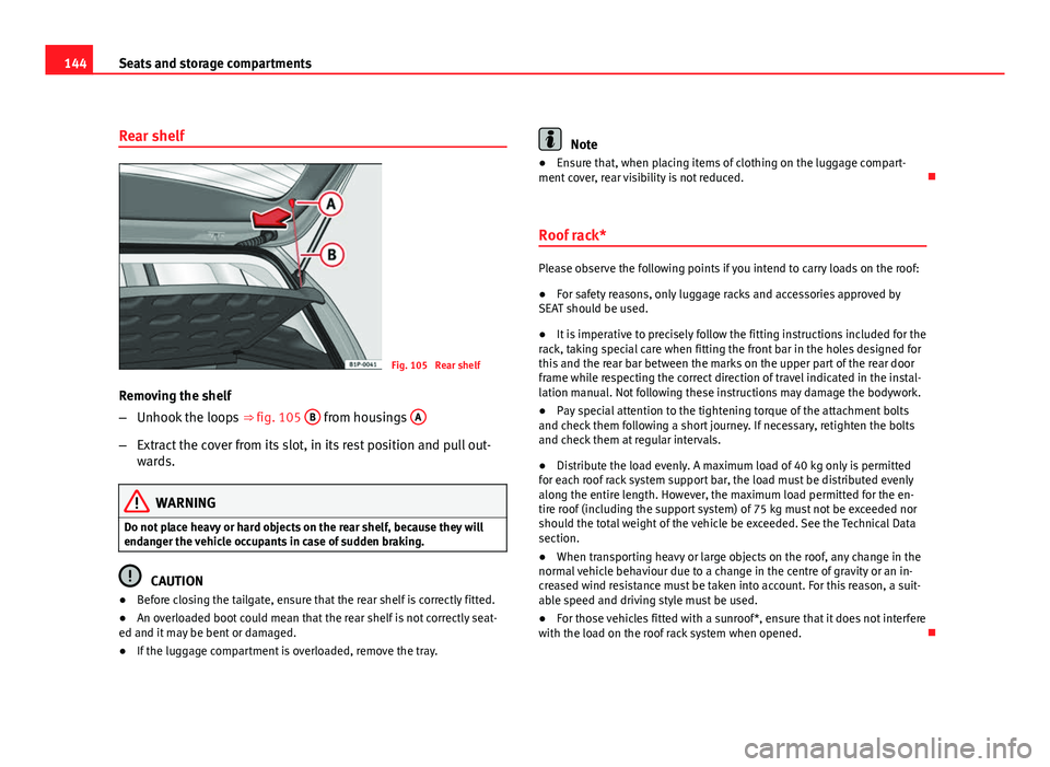
Fig. 105 Rear shelf
Removing the shelf
– Unhook the loops ⇒ fig. 105 B
from housings A
–
Extract the cover from its slot, in its rest position and pull out-
wards.
WARNING
Do not place heavy or hard objects on the rear shelf, because they will
endanger the vehicle occupants in case of sudden braking.
CAUTION
● Before closing the tailgate, ensure that the rear shelf is correctly fitted.
● An overloaded boot could mean that the rear shelf is not correctly seat-
ed and it may be bent or damaged.
● If the luggage compartment is overloaded, remove the tray.
Note
● Ensure that, when placing items of clothing on the luggage compart-
ment cover, rear visibility is not reduced.
Roof rack*
Please observe the following points if you intend to carry loads on the roof:
● For safety reasons, only luggage racks and accessories approved by
SEAT should be used.
● It is imperative to precisely follow the fitting instructions included for the
rack, taking special care when fitting the front bar in the holes designed for
this and the rear bar between the marks on the upper part of the rear door
frame while respecting the correct direction of travel indicated in the instal-
lation manual. Not following these instructions may damage the bodywork.
● Pay special attention to the tightening torque of the attachment bolts
and check them following a short journey. If necessary, retighten the bolts
and check them at regular intervals.
● Distribute the load evenly. A maximum load of 40 kg only is permitted
for each roof rack system support bar, the load must be distributed evenly
along the entire length. However, the maximum load permitted for the en-
tire roof (including the support system) of 75 kg must not be exceeded nor
should the total weight of the vehicle be exceeded. See the Technical Data
section.
● When transporting heavy or large objects on the roof, any change in the
normal vehicle behaviour due to a change in the centre of gravity or an in-
creased wind resistance must be taken into account. For this reason, a suit-
able speed and driving style must be used.
● For those vehicles fitted with a sunroof*, ensure that it does not interfere
with the load on the roof rack system when opened.