ESP Seat Leon 5D 2011 Workshop Manual
[x] Cancel search | Manufacturer: SEAT, Model Year: 2011, Model line: Leon 5D, Model: Seat Leon 5D 2011Pages: 302, PDF Size: 4.17 MB
Page 223 of 302
221
Checking and refilling levels
Vehicles with diesel particulate filter*
The “Maintenance Programme” states whether your vehicle is fitted with a
diesel particulate filter.
Only VW 507 00 engine oil, with reduced ash formation, may be used in die-
sel engines equipped with particulate filter. Using other types of oil will
cause a higher soot concentration and reduce the life of the DPF. Therefore:
● Avoid mixing this oil with other engine oils.
● Only in exceptional circumstances, if the engine oil level is too low
⇒ page 221 and you cannot obtain the oil specified for your vehicle, you
can use a small quantity of oil (once) conforming to the VW 506 00,
VW 506 01, VW 505 00, VW 505 01 or ACEA B3 / ACEA B4 specification. (up
to 0.5 l).
Oil properties
Engine typeSpecificationPetrol without flexible service in-
tervalVW 502 00/ VW 504 00
Petrol with flexible service inter-
val (LongLife)VW 504 00
Diesel. Engines without Particu-
late filter (DPF)VW 505 01 / VW 506 01 / VW 507 00
Diesel. Engines with particulate
filter (DPF)
With or without flexible service in-
terval (with or without LongLife) a)VW 507 00
a)
Only use recommended oils, otherwise you may damage the engine.
Engine oil additives
No type of additive should be mixed with the engine oil. The deterioration
caused by these additives is not covered by the warranty.
Note
Before a long trip, we recommend finding an engine oil that conforms to the
corresponding VW specifications and keeping it in the vehicle. This way, the
correct engine oil will always be available for a top-up if needed.
Checking the engine oil level
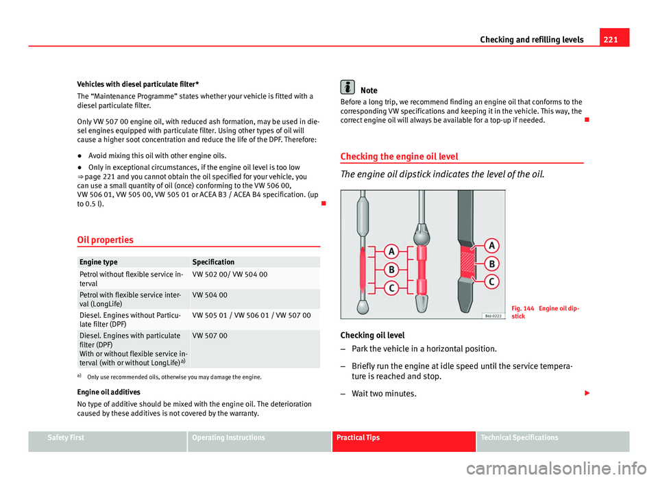
The engine oil dipstick indicates the level of the oil.
Fig. 144 Engine oil dip-
stick
Checking oil level
– Park the vehicle in a horizontal position.
– Briefly run the engine at idle speed until the service tempera-
ture is reached and stop.
– Wait two minutes.
Safety FirstOperating InstructionsPractical TipsTechnical Specifications
Page 224 of 302
222Checking and refilling levels
–Pull out the dipstick. Wipe the dipstick with a clean cloth and
insert it again, pushing it in as far as it will go.
– Then pull it out once more and check the oil level ⇒ fig. 144.
Top up with engine oil if necessary.
Oil level in area A
Do not add oil.
Oil level in area B
Oil
can be topped up. The indicated oil level should be after in zone A
Oil level in area COil
must be topped up. The indicated oil level should be after in zone
A
Depending on how you drive and the conditions in which the vehicle is
used, oil consumption can be up to 0.5 l/1000 km. Oil consumption is likely
to be higher for the first 5000 km. For this reason the engine oil level must
be checked at regular intervals, preferably when filling the tank and before
a journey.
WARNING
Any work carried out in the engine compartment or on the engine must
be carried out cautiously.
● When working in the engine compartment, always observe the safety
warnings ⇒ page 217.
CAUTION
If the oil level is above the area A do not start the engine. This could result
in damage to the engine and catalytic converter. Contact an Authorised
Service Centre.
–
–
–
Topping up engine oil
Top up gradually with small quantities of oil.
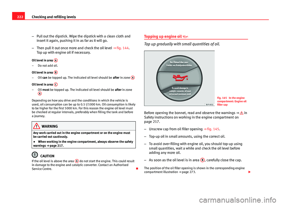
Fig. 145 In the engine
compartment: Engine oil
filler cap
Before opening the bonnet, read and observe the warnings ⇒
in
Safety instructions on working in the engine compartment on
page 217.
– Unscrew cap from oil filler opening ⇒ fig. 145.
– Top-up oil in small amounts, using the correct oil.
– To avoid over-filling with engine oil, you should top-up using
small quantities, wait a while and check the oil level before
adding any more oil.
– As soon as the oil level is in area B
, carefully close the cap.
The position of the oil filler opening is shown in the corresponding engine
compartment illustration ⇒ page 273.
Page 227 of 302

225
Checking and refilling levels
Opening the coolant expansion tank
– Switch off the engine and allow it to cool.
– To prevent scalding, cover the cap on the expansion tank with a
thick cloth and carefully unscrew the cap ⇒
.
Checking coolant level
– Look into the open coolant expansion tank and read off the
coolant level.
– If the level is below the “MIN” mark, top up with coolant.
Topping up coolant
– Only use new coolant liquid.
– Do not fill above the “MAX” mark.
Closing the coolant expansion tank
– Screw the cap on again tightly.
The position of the coolant expansion reservoir is shown in the correspond-
ing engine compartment illustration ⇒ page 273.
Make sure that the coolant meets the required specifications ⇒ page 224.
Do not use a different type of additive if additive G 12+ is not available. In
this case use only water and bring the coolant concentration back up to the
correct level as soon as possible by putting in the specified additive
⇒ page 224.
Always top up with new coolant.
Do not fill above the “MAX” mark. Otherwise the excess coolant will be
forced out of the cooling system when the engine is hot.
The additive G 12+ (purple) may be mixed with G 12 (red) and also with G
11.
WARNING
Any work carried out in the engine compartment or on the engine must
be carried out cautiously.
● When working in the engine compartment, always observe the safety
warnings ⇒ page 217.
● When the engine is warm or hot, the cooling system is pressurised!
Do not unscrew the cap on the expansion tank when the engine is hot.
This is a burn injury risk.
CAUTION
● When mixed with other additives the colour of G 12 will change to
brown. If this occurs you should have the coolant changed immediately.
Failure to do so will result in engine damage!
● If a lot of coolant fluid has been lost, wait for the engine to cool down
before putting in cold coolant. This avoids damaging the engine. Large cool-
ant losses are an indication of leaks in the cooling system. See a special-
ised workshop immediately and have the cooling system checked. Other-
wise, there is a risk of engine damage.
Safety FirstOperating InstructionsPractical TipsTechnical Specifications
Page 231 of 302

229
Checking and refilling levels
Brake fluid Checking the brake fluid level
The brake fluid is checked at the intervals given in the serv-
ice schedule.
Fig. 151 In the engine
compartment: Brake fluid
reservoir cover
– Read off the fluid level at the transparent brake fluid reservoir. It
should always be between the “MIN” and “MAX” marks.
The position of the brake fluid reservoir is shown in the corresponding en-
gine compartment illustration ⇒ page 273. The brake fluid reservoir has a
black and yellow cap.
The brake fluid level drops slightly when the vehicle is being used as the
brake pads are automatically adjusted as they wear.
However, if the level goes down noticeably in a short time, or drops below
the “MIN” mark, there may be a leak in the brake system. A display on the
instrument panel will warn you if the brake fluid level is too low ⇒ page 77.
WARNING
Before opening the bonnet to check the brake fluid level, read and ob-
serve the warnings ⇒ page 217.
Changing the brake fluid
The Maintenance Programme indicates the brake fluid
change intervals. We recommend that you have the brake fluid changed by an Authorised
Service Centre.
Before opening the bonnet, please read and follow the warnings ⇒
in
Safety instructions on working in the engine compartment on page 217 in
section “Safety notes for working in the engine compartment”.
Brake fluid absorbs moisture. In the course of time, it will absorb water from
the ambient air. If the water content in the brake fluid is too high, the brake
system could corrode. This also considerably reduces the boiling point of
the brake fluid. Heavy use of the brakes may then cause a vapour lock
which could impair the braking effect.
It is important that you use only brake fluid compliant with US standard
FMVSS 116 DOT 4. We recommend the use of Genuine SEAT brake fluid.
WARNING
Brake fluid is poisonous. Old brake fluid impairs the braking effect.
● Before opening the bonnet to check the brake fluid level, read and ob-
serve the warnings ⇒ page 217.
Safety FirstOperating InstructionsPractical TipsTechnical Specifications
Page 233 of 302
231
Checking and refilling levels
WARNING (Continued)
● Deactivate the anti-theft alarm by unlocking the vehicle before you
disconnect the battery! The alarm will otherwise be triggered.
● When disconnecting the battery from the vehicle electrical system,
disconnect first the negative cable and then the positive cable.
● Switch off all electrical consumers before reconnecting the battery.
Reconnect first the positive cable and then the negative cable. Never re-
verse the polarity of the connections. This could cause an electrical fire.
● Never charge a frozen battery, or one which has thawed. This could
result in explosions and chemical burns. Always replace a battery which
has frozen. A flat battery can freeze at temperatures around 0°C.
● Ensure that the vent hose is always connected to the battery.
● Never use a defective battery. This could cause an explosion. Replace
a damaged battery immediately.
CAUTION
● Never disconnect the battery if the ignition is switched on or if the en-
gine is running. This could damage the electrical system or electronic com-
ponents.
● Do not expose the battery to direct sunlight over a long period of time,
as the intense ultraviolet radiation can damage the battery housing.
● If the vehicle is left standing in cold conditions for a long period, protect
the battery from freezing. If it freezes it will be damaged. Checking the electrolyte level
The electrolyte level should be checked regularly in high-
mileage vehicles, in hot countries and in older batteries.
– Open the engine bonnet and the battery cover ⇒
in Safety in-
structions on working in the engine compartment on page 217
⇒
in Warnings on handling the battery on page 230.
– Check the colour display in the "magic eye" on the top of the
battery.
– If there are air bubbles in the window, tap the window gently
until they disperse.
The position of the battery is shown in the corresponding engine compart-
ment diagram ⇒ page 273.
The “magic eye” indicator, located on the top of the battery changes colour,
depending on the charge state and electrolyte level of the battery.
There are two different colours:
● Black: correct charge status.
● Transparent/clear yellow: the battery must be replaced. Contact a spe-
cialist workshop.
Safety FirstOperating InstructionsPractical TipsTechnical Specifications
Page 236 of 302
234Wheels and tyres
2. The tyre pressures should only be checked when the tyres are
cold. The slightly raised pressures of warm tyres must not be re-
duced.
3. Adjust the tyre pressure to the load you are carrying.
Tyre pressure
The correct tyre pressure is especially important at high speeds. The pres-
sure should therefore be checked at least once a month and before starting
a journey.
The sticker with the tyre pressure values can be found on the inside of the
tank flap. The tyre pressure values given are for cold tyres. Do not reduce
the slightly raised pressures of warm tyres ⇒
.
WARNING
● Check the tyre pressure at least once per month. Checking the tyre
pressure is very important. If the tyre pressure is too high or too low,
there is an increased danger of accidents - particularly at high speeds.
● A tyre can easily burst if the pressure is too low, causing an accident!
● At continuously high speeds, a tyre with insufficient pressure flexes
more. In this way it becomes too hot, and this can cause tread separation
and tyre blow-out. Always observe the recommended tyre pressures.
● If the tyre pressure is too low or too high, the tyres will wear prema-
turely and the vehicle will not handle well. Risk of accident!
For the sake of the environment
Under-inflated tyres will increase fuel consumption. Tyre pressure monitoring
The tyre pressure monitoring system constantly checks the
pressure of the tyres.
The system uses the speed sensors of the ABS wheels. It operates by analy-
sing the speed and frequency spectrum of each wheel.
For optimum performance, use genuine SEAT tyres. In addition, check and
adjust tyre pressures regularly.
Whenever the tyre pressures are changed or one or more tyres are changed,
the system should be Reset by pressing the SET switch on the centre con-
sole.
The system warns the driver in the event of a loss of pressure by means of
symbols and messages in the instrument panel display. The system uses
ESC (ESP) ⇒ page 184.
Note that tyre pressure also depends on tyre temperature. Tyre pressure in-
creases about 0.1 bar for each 10°C in tyre temperature increase. The tyre
heats up while the vehicle is being driven and the tyre pressure will rise ac-
cordingly. For this reason, you should only adjust the tyre pressures when
they are cold (i.e. approximately at ambient temperature).
To ensure that the tyre pressure monitoring system works reliably, you
should check and, if necessary, adjust the tyre pressures at regular intervals
and store the correct pressures (reference values) in the system.
A tyre pressure information label is attached to the inside of the fuel tank
flap.
Page 239 of 302
237
Wheels and tyres
Run-flat tyres
Run-flat tyres allow you to continue driving even with a
punctured tyre, in the majority of cases.
In vehicles that are factory-fitted with run-flat tyres 1)
the loss of tyre
pressure is indicated on the instrument panel.
Driving with run-flat tyres (emergency running)
– Leave the ESC (ESP)/ASR (TCS) (Electronic Stability Control) acti-
vated, or activate it ⇒ page 183.
– Continue driving carefully and slowly (80 km/h maximum).
– Avoid sudden manoeuvres and sharp turns.
– Avoid driving over obstacles (for example kerbs) or potholes.
– Look out for the ESC (ESP)/ASR (TCS) intervening often, smoke
coming from the tyres or the smell of rubber, the vehicle vibrat-
ing or a clattering noise. If any of these occur, stop the vehicle.
The run-flat tyres have a tag on the side of the tyre, with the description:
“DSST”, “Eufonia”, “RFT”, “ROF”, “RSC”, “SSR” or “ZP”.
The sides of this type of tyre are reinforced. When the tyres lose air they are
supported on the sides (emergency driving).
The loss of pressure in the tyre is shown on the instrument panel. You can
then drive a maximum of 80 km and if the circumstances are favourable (for
example, low load), even more.
The damaged tyre should be changed as soon as possible. The rim should
be checked in a specialist workshop to detect possible damage and replace it if necessary. We recommend you contact Technical Service. If more than
one tyre is being used under emergency conditions, this reduces the dis-
tance which can be travelled.
Starting driving in emergency conditions
When loss in tyre pressure is displayed on the instrument panel, this means
that at least one tyre is being driven in emergency conditions
⇒
.
End of emergency operation
Do not drive on if:
● smoke is coming from one of the tyres,
● there is a smell of rubber,
● the vehicle vibrates,
● there is a rattling noise.
When is it no longer possible to continue driving even using run-flat tyres?
● If one of the tyres has been severely damaged in an accident, etc. If a
tyre has been badly damaged there is a risk that parts of the tread can be
thrown off and cause damage to the fuel lines, brake pipes or fuel filler.
● It is also advisable to stop driving if severe vibrations occur, or if the
wheel starts overheating and gives off smoke.
WARNING
When driving in emergency conditions, the driving quality of the vehicle
is considerably impaired.
● The maximum permitted speed of 80 km/h is subject to road and
weather conditions. Please observe legal requirements when doing so.
● Avoid sharp turns and rapid manoeuvres, and brake earlier than usu-
al.
1)
Depending upon version and country.
Safety FirstOperating InstructionsPractical TipsTechnical Specifications
Page 245 of 302
243
If and when
– All passengers should leave the vehicle. They should wait in a
safe area (for instance behind the roadside crash barrier).
– Switch off the engine. Switch on the hazard warning lights.
– Apply the handbrake firmly.
– Engage the first gear , or put the selector lever to position P for
those vehicles with an automatic gearbox.
– If you are towing a trailer, unhitch it from your vehicle.
– Take the vehicle tools and the spare wheel out of the luggage
compartment.
WARNING
Put the hazard warning lights on and place the warning triangle in posi-
tion. This is for your own safety and also warns other road users.
CAUTION
If you have to change the wheel on a gradient, block the wheel opposite the
wheel being changed by placing a stone or similar object under it to prevent
the vehicle from rolling away.
Note
Please observe legal requirements when doing so.
Changing a wheel
Change the wheel as described below
– Pull off the hub cap. See ⇒ fig. 155. –
Slacken the wheel bolts.
– Raise the car with the jack at the corresponding point.
– Remove the wheel and then mount the spare wheel
– Lower the vehicle.
– Tighten the wheel bolts firmly with the box spanner.
– Replace the wheel trim.
After changing a wheel
After changing the wheel there are still tasks to complete. – Put the tools and jack back in the luggage compartment.
– Place the wheel with the defective tyre in the luggage compart-
ment and secure it.
– Check the tyre pressure of the newly fitted tyre as soon as pos-
sible.
– Have the tightening torque of the wheel bolts checked as soon
as possible with a torque wrench. The prescribed torque must
be 120 Nm.
Note
● If you notice that the wheel bolts are corroded and difficult to turn when
changing a wheel, they must be replaced before having the wheel bolt tor-
que checked.
● For safety reasons, drive at moderate speeds until the wheel bolt tight-
ening torque has been checked.
Safety FirstOperating InstructionsPractical TipsTechnical Specifications
Page 252 of 302
250If and when
Fuses
Changing a fuse
Blown fuses must be replaced
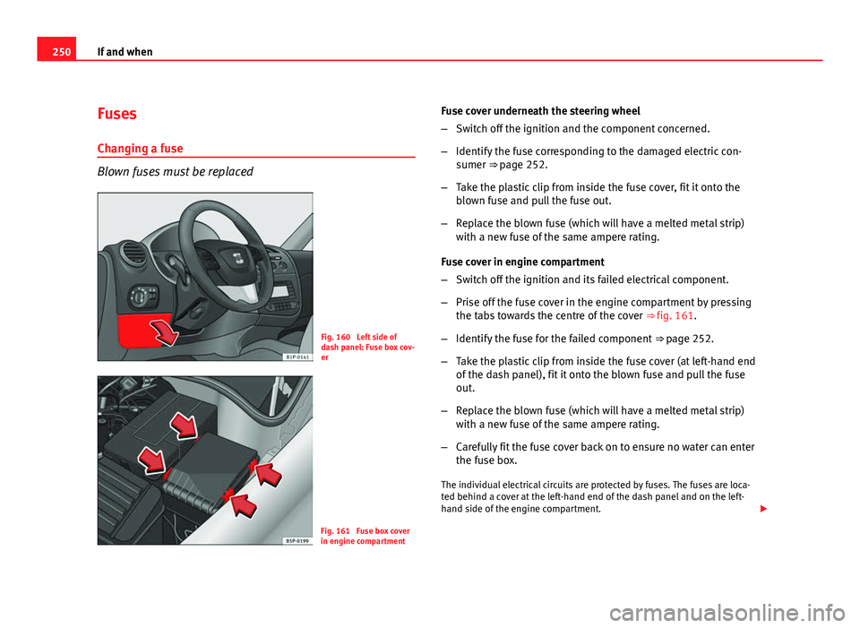
Fig. 160 Left side of
dash panel: Fuse box cov-
er
Fig. 161 Fuse box cover
in engine compartment Fuse cover underneath the steering wheel
–
Switch off the ignition and the component concerned.
– Identify the fuse corresponding to the damaged electric con-
sumer ⇒ page 252.
– Take the plastic clip from inside the fuse cover, fit it onto the
blown fuse and pull the fuse out.
– Replace the blown fuse (which will have a melted metal strip)
with a new fuse of the same ampere rating.
Fuse cover in engine compartment
– Switch off the ignition and its failed electrical component.
– Prise off the fuse cover in the engine compartment by pressing
the tabs towards the centre of the cover ⇒ fig. 161.
– Identify the fuse for the failed component ⇒ page 252.
– Take the plastic clip from inside the fuse cover (at left-hand end
of the dash panel), fit it onto the blown fuse and pull the fuse
out.
– Replace the blown fuse (which will have a melted metal strip)
with a new fuse of the same ampere rating.
– Carefully fit the fuse cover back on to ensure no water can enter
the fuse box.
The individual electrical circuits are protected by fuses. The fuses are loca-
ted behind a cover at the left-hand end of the dash panel and on the left-
hand side of the engine compartment.
Page 254 of 302
252If and when
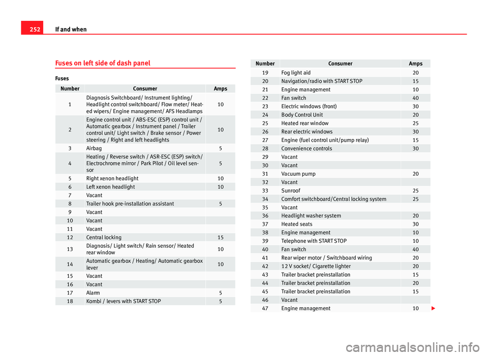
Fuses on left side of dash panel
Fuses
NumberConsumerAmps
1Diagnosis Switchboard/ Instrument lighting/
Headlight control switchboard/ Flow meter/ Heat-
ed wipers/ Engine management/ AFS Headlamps10
2
Engine control unit / ABS-ESC (ESP) control unit /
Automatic gearbox / Instrument panel / Trailer
control unit/ Light switch / Brake sensor / Power
steering / Right and left headlights
10
3Airbag5
4Heating / Reverse switch / ASR-ESC (ESP) switch/
Electrochrome mirror / Park Pilot / Oil level sen-
sor5
5Right xenon headlight106Left xenon headlight107Vacant 8Trailer hook pre-installation assistant59Vacant 10Vacant 11Vacant 12Central locking15
13Diagnosis/ Light switch/ Rain sensor/ Heated
rear window10
14Automatic gearbox / Heating/ Automatic gearbox
lever10
15Vacant 16Vacant 17Alarm518Kombi / levers with START STOP5
NumberConsumerAmps19Fog light aid2020Navigation/radio with START STOP1521Engine management1022Fan switch4023Electric windows (front)3024Body Control Unit2025Heated rear window2526Rear electric windows3027Engine (fuel control unit/pump relay)1528Convenience controls3029Vacant 30Vacant 31Vacuum pump2032Vacant 33Sunroof2534Comfort switchboard/Central locking system2535Vacant 36Headlight washer system2037Heated seats3038Engine management1039Telephone with START STOP1040Fan switch4041Rear wiper motor / Switchboard wiring204212 V socket/ Cigarette lighter2043Trailer bracket preinstallation1544Trailer bracket preinstallation2045Trailer bracket preinstallation1546Vacant 47Engine management10