ad blue Seat Leon 5D 2012 Owner's manual
[x] Cancel search | Manufacturer: SEAT, Model Year: 2012, Model line: Leon 5D, Model: Seat Leon 5D 2012Pages: 289, PDF Size: 3.81 MB
Page 72 of 289
71
Instruments and warning/control lamps
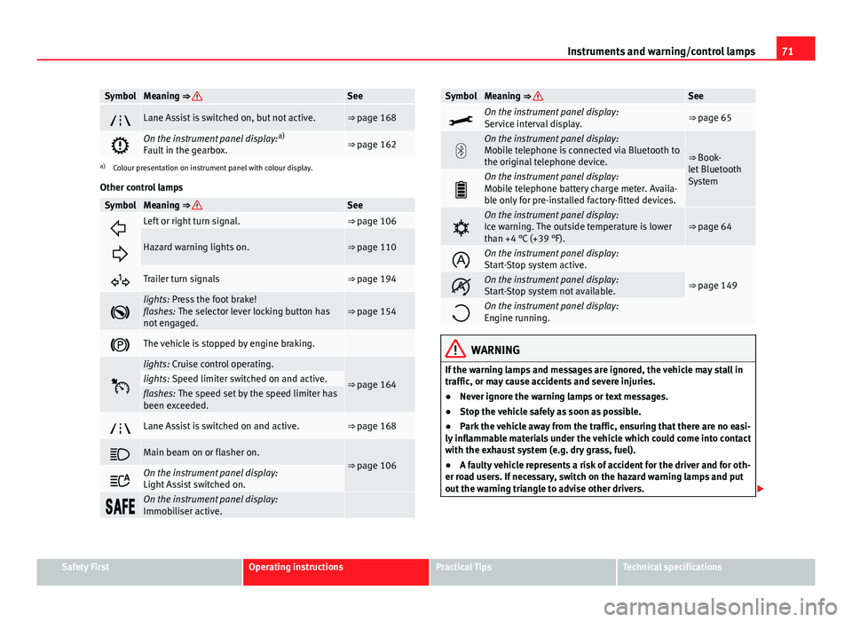
SymbolMeaning ⇒ See
Lane Assist is switched on, but not active.⇒ page 168
On the instrument panel display: a)
Fault in the gearbox.⇒ page 162
a) Colour presentation on instrument panel with colour display.
Other control lamps
SymbolMeaning ⇒ See
Left or right turn signal.⇒ page 106
Hazard warning lights on.⇒ page 110
Trailer turn signals⇒ page 194
lights: Press the foot brake!
flashes: The selector lever locking button has
not engaged.⇒ page 154
The vehicle is stopped by engine braking.
lights: Cruise control operating.
⇒ page 164lights: Speed limiter switched on and active.flashes: The speed set by the speed limiter has
been exceeded.
Lane Assist is switched on and active.⇒ page 168
Main beam on or flasher on.⇒ page 106
On the instrument panel display:
Light Assist switched on.
On the instrument panel display:
Immobiliser active.
SymbolMeaning ⇒ See
On the instrument panel display:
Service interval display.⇒ page 65
On the instrument panel display:
Mobile telephone is connected via Bluetooth to
the original telephone device.
⇒ Book-
let Bluetooth
System
On the instrument panel display:
Mobile telephone battery charge meter. Availa-
ble only for pre-installed factory-fitted devices.
On the instrument panel display:
Ice warning. The outside temperature is lower
than +4 °C (+39 °F).⇒ page 64
On the instrument panel display:
Start-Stop system active.
⇒ page 149On the instrument panel display:
Start-Stop system not available.
On the instrument panel display:
Engine running.
WARNING
If the warning lamps and messages are ignored, the vehicle may stall in
traffic, or may cause accidents and severe injuries.
● Never ignore the warning lamps or text messages.
● Stop the vehicle safely as soon as possible.
● Park the vehicle away from the traffic, ensuring that there are no easi-
ly inflammable materials under the vehicle which could come into contact
with the exhaust system (e.g. dry grass, fuel).
● A faulty vehicle represents a risk of accident for the driver and for oth-
er road users. If necessary, switch on the hazard warning lamps and put
out the warning triangle to advise other drivers.
Safety FirstOperating instructionsPractical TipsTechnical specifications
Page 74 of 289
73
Driver information system
Driver information system Information system
Introduction
With the ignition switched on, it is possible to read the different functions of
the display by scrolling through the menus.
In vehicles with multifunction steering wheel, the multifunction display can
only be operated with the multifunction steering wheel buttons.
The number of menus displayed on the instrument panel will vary according
to the vehicle electronics and equipment.
A specialised workshop will be able to programme or modify additional
functions, according to the vehicle equipment. SEAT recommends visiting a
SEAT Official Service.
Some menu options can only be read when the vehicle is at a standstill.
As long as a priority 1 warning is displayed, it will not be possible to read
the menus. Some warning messages can be confirmed and made to disap-
pear with the windscreen wiper lever button or the multifunction steering
wheel button.
Additional information and warnings:
● Easy Connect system ⇒ page 79
● Driver assistance systems ⇒ page 164
● Radio or navigation system ⇒ Booklet Radio or ⇒ Booklet Navigation
system
WARNING
Any distraction may lead to an accident, with the risk of injury.
● Do not read the instrument panel display menus when driving.
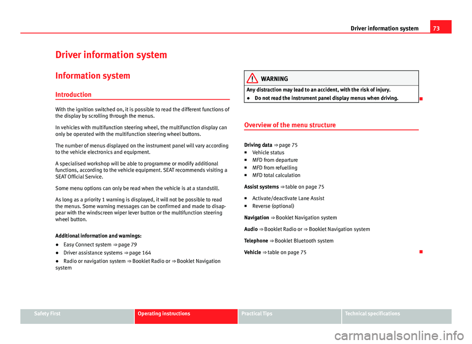
Overview of the menu structure
Driving data ⇒ page 75
■ Vehicle status
■ MFD from departure
■ MFD from refuelling
■ MFD total calculation
Assist systems ⇒ table on page 75
■ Activate/deactivate Lane Assist
■ Reverse (optional)
Navigation ⇒ Booklet Navigation system Audio ⇒ Booklet Radio or ⇒ Booklet Navigation systemTelephone ⇒ Booklet Bluetooth systemVehicle ⇒ table on page 75
Safety FirstOperating instructionsPractical TipsTechnical specifications
Page 76 of 289
75
Driver information system
Button for the driving assistance systems
Fig. 42 On the turn sig-
nal and main beam head-
light lever: button for the
driving assistance sys-
tems
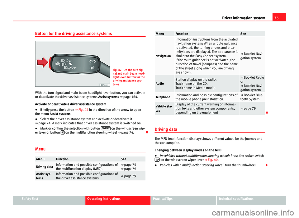
With the turn signal and main beam headlight lever button, you can activate
or deactivate the driver assistance systems Assist systems ⇒ page 164.
Activate or deactivate a driver assistance system
● Briefly press the button ⇒ Fig. 42 in the direction of the arrow to open
the menu Assist systems .
● Select the driver assistance system and activate or deactivate it
⇒ page 74. A mark indicates that driver assistance system is switched on.
● Mark or confirm the selection with button
on the windscreen wip-
er lever or button on the multifunction steering wheel
⇒ page 74.
Menu
MenuFunctionSee
Driving dataInformation and possible configurations of
the multifunction display (MFD).⇒ page 75
⇒ page 79
Assist sys-
temsInformation and possible configurations of
the driver assistance systems.⇒ page 79
MenuFunctionSee
Navigation
Information instructions from the activated
navigation system: When a route guidance
is activated, the turning arrows and prox-
imity bars are displayed. The appearance is
similar to the Easy Connect system.
If the route guidance is not activated, the
direction of travel (compass) and the name
of the street along which you are driving
are shown.
⇒ Booklet Navi-
gation system
AudioStation display on the radio.
Track name on the CD.
Track name in Media mode.⇒ Booklet Radio
or
⇒ Booklet Navi-
gation system
TelephoneInformation and possible configurations of
the mobile phone preinstallation.⇒ Booklet Blue-
tooth System
Vehicle sta-
tusDisplay of the current warning or informa-
tion texts and other system components,
depending on the equipment⇒ page 79
Driving data
The MFD (multifunction display) shows different values for the journey and
the consumption.
Changing between display modes on the MFD
● In vehicles without multifunction steering wheel: Press the rocker switch
on the windscreen wiper lever ⇒ Fig. 40.
● Vehicles with a multifunction steering wheel: turn the thumbwheel.
Safety FirstOperating instructionsPractical TipsTechnical specifications
Page 138 of 289
137
Air conditioning
To switch a function on or off, or to select a submenu, you must press the
corresponding function button.
For more information about functions ⇒ page 79.
Function
buttonFunction
OFFSwitch off and switch on the Climatronic.
SETTINGS
The air conditioning settings submenu is opened. It is possi-
ble to make the following adjustments:
Function button Air conditioning profile.
: to adjust the level of the
fan in AUTO mode. You can choose between low, medium and
high.
Function button Automatic air recirculation
to switch on and off au-
tomatic air recirculation ⇒ page 141.
BACK
function button to close the submenu.
Operating by using the Easy Connect* system (valid for
Standard Radio)
In the Easy Connect system it is also possible to perform various adjust-
ments to the Climatronic.
Open the air conditioner menu
● Press the Setup
button
On the top of the screen you can see and change the current settings, such
as, for example, the temperature set for the driver side and for that of pas-
senger. Temperatures up to +22 ° C (+72 ° F) are shown with blue arrows,
and temperatures over +22 ° C (+72 ° F) with red arrows.
To switch a function on or off, or to select a submenu, you must press the
corresponding function button.
Function buttonFunction
Air conditioning profileAdjust the fan level in AUTO mode. You can choose be-
tween low, medium and high.
Climatronic is switched off.
Climatronic is switched on.
SETTINGS
The air conditioning settings submenu is opened. It is
possible to make the following adjustments:
Function button Air conditioning profile.
: to adjust the level
of the fan in AUTO mode. You can choose between low,
medium and high.
Function button Automatic air recirculation
to switch on and
off automatic air recirculation ⇒ page 141.
BACK
function button to close the submenu.
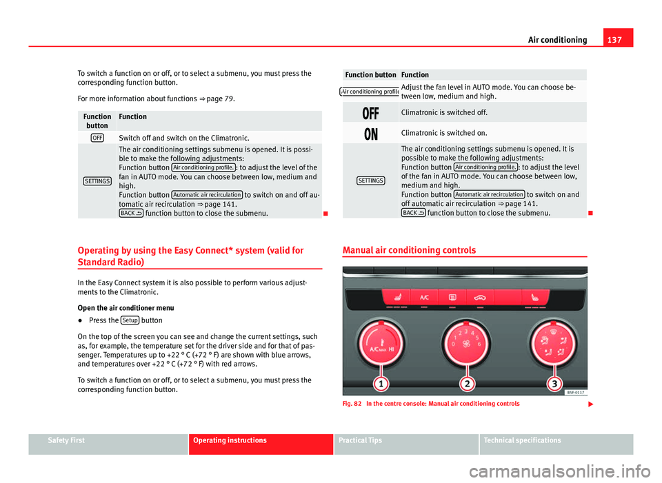
Manual air conditioning controls
Fig. 82 In the centre console: Manual air conditioning controls
Safety FirstOperating instructionsPractical TipsTechnical specifications
Page 216 of 289
215
Checking and refilling levels
Cooling system Engine coolant specifications
The engine cooling system is supplied from the factory with a specially trea-
ted mixture of water and, at least, 40 % of the additive G 13 (TLVW 774 J).
The engine coolant additive is recognisable by its purple colour. This mix-
ture of water and additive gives the necessary frost protection down to
-25°C (-13 F) and protects the light alloy parts of the cooling system against
corrosion. It also prevents scaling and considerably raises the boiling point
of the coolant.
To protect the engine cooling system, the percentage of additive must al-
ways be at least 40 %, even in warm climates where anti-freeze protection is
not required.
If greater frost protection is required in very cold climates, the proportion of
additive can be increased. However, the percentage of additive should not
exceed 60 %, as this would reduce the frost protection and, in turn, de-
crease the cooling capacity.
When the coolant is topped up, use a mixture of distilled water and, at
least, 40 % of the G 13 or G 12 plus-plus (TL-VW 774 G) additive (both are
purple) to obtain an optimum anticorrosion protection ⇒
. The mixture of
G 13 with G 12 plus (TL-VW 774 F), G 12 (red) or G 11 (green-blue) engine
coolants will significantly reduce the anticorrosion protection and should,
therefore be avoided ⇒
.
WARNING
If there is not enough anti-freeze in the coolant system, the engine may
fail leading to serious damage.
● Please make sure that the percentage of additive is correct with re-
spect to the lowest expected ambient temperature in the zone in which
the vehicle is to be used.
● When the outside temperature is very low, the coolant could freeze
and the vehicle would be immobilised. In this case, the heating would
not work either and inadequately dressed passengers could die of cold.
CAUTION
The original additives should never be mixed with coolants which are not
approved by SEAT. Otherwise, you run the risk of causing severe damage to
the engine and the engine cooling system.
● If the fluid in the expansion tank is not purple but is, for example,
brown, this indicates that the G 13 additive has been mixed with an inade-
quate coolant. The coolant must be changed as soon as possible if this is
the case! This could result in serious faults and engine damage.
For the sake of the environment
Coolants and additives can contaminate the environment. If any fluids are
spilled, they should be collected and correctly disposed of, with respect to
the environment.
Safety FirstOperating instructionsPractical TipsTechnical specifications