technical data Seat Leon 5D 2012 Owner's manual
[x] Cancel search | Manufacturer: SEAT, Model Year: 2012, Model line: Leon 5D, Model: Seat Leon 5D 2012Pages: 289, PDF Size: 3.81 MB
Page 5 of 289
Trailer . . . . . . . . . . . . . . . . . . . . . . . . . . . . . . . . . . . . . 194
Trailer towing . . . . . . . . . . . . . . . . . . . . . . . . . . . . . 194
Retrofitting a towing bracket* . . . . . . . . . . . . . . . 196
Care and cleaning . . . . . . . . . . . . . . . . . . . . . . . . . 198
General information . . . . . . . . . . . . . . . . . . . . . . . 198
Care of vehicle exterior . . . . . . . . . . . . . . . . . . . . . 198
Care of the vehicle interior . . . . . . . . . . . . . . . . . . 202
Checking and refilling levels . . . . . . . . . . . . . . . 206
Fuel . . . . . . . . . . . . . . . . . . . . . . . . . . . . . . . . . . . . 206
Filling the tank . . . . . . . . . . . . . . . . . . . . . . . . . . . . 207
Bonnet . . . . . . . . . . . . . . . . . . . . . . . . . . . . . . . . . . 209
Engine oil . . . . . . . . . . . . . . . . . . . . . . . . . . . . . . . . 211
Cooling system . . . . . . . . . . . . . . . . . . . . . . . . . . . 215
Brake fluid . . . . . . . . . . . . . . . . . . . . . . . . . . . . . . . 217
Battery . . . . . . . . . . . . . . . . . . . . . . . . . . . . . . . . . . 217
Windscreen washer reservoir and wiper blades . 220
Wheels and tyres . . . . . . . . . . . . . . . . . . . . . . . . . . 223
Wheels . . . . . . . . . . . . . . . . . . . . . . . . . . . . . . . . . . 223
Accessories and modifications to the vehicle 230
Accessories, replacement parts and repairs . . . . 230
Technical modifications . . . . . . . . . . . . . . . . . . . . 230
Radio transmitters and business equipment . . . 230
Emergencies . . . . . . . . . . . . . . . . . . . . . . . . . . . . . . 232
General information . . . . . . . . . . . . . . . . . . . . . . . 232
Equipment . . . . . . . . . . . . . . . . . . . . . . . . . . . . . . . 232
Tyre repair kit . . . . . . . . . . . . . . . . . . . . . . . . . . . . . 233
Changing a wheel . . . . . . . . . . . . . . . . . . . . . . . . . 235
Spare wheel . . . . . . . . . . . . . . . . . . . . . . . . . . . . . . 240
Jump starting . . . . . . . . . . . . . . . . . . . . . . . . . . . . . 241
Towing and tow-starting the vehicle . . . . . . . . . . 244
Fuses and bulbs . . . . . . . . . . . . . . . . . . . . . . . . . . . 249
Electrical fuses . . . . . . . . . . . . . . . . . . . . . . . . . . . 249
Bulbs . . . . . . . . . . . . . . . . . . . . . . . . . . . . . . . . . . . 252
Changing bulbs in headlight unit . . . . . . . . . . . . 254
Changing bulb for front fog light . . . . . . . . . . . . . 256
Changing tail light bulbs (on side panel) . . . . . . 257 Changing tail light bulbs (on rear lid) . . . . . . . . . 259
Changing number plate light bulbs . . . . . . . . . . . 261
Technical specifications . . . . . . . . . . . . 263
Technical specifications . . . . . . . . . . . . . . . . . . . . 263
Important . . . . . . . . . . . . . . . . . . . . . . . . . . . . . . . . 263
Vehicle identification data . . . . . . . . . . . . . . . . . . 264
Information on fuel consumption . . . . . . . . . . . . 265
Towing a trailer . . . . . . . . . . . . . . . . . . . . . . . . . . . 265
Wheels . . . . . . . . . . . . . . . . . . . . . . . . . . . . . . . . . . 266
Engine specifications . . . . . . . . . . . . . . . . . . . . . . 267
Dimensions and capacities . . . . . . . . . . . . . . . . . 276
Index . . . . . . . . . . . . . . . . . . . . . . . . . . . . . . . . . . . 277
4Table of Contents
Page 68 of 289
67
Instruments and warning/control lamps
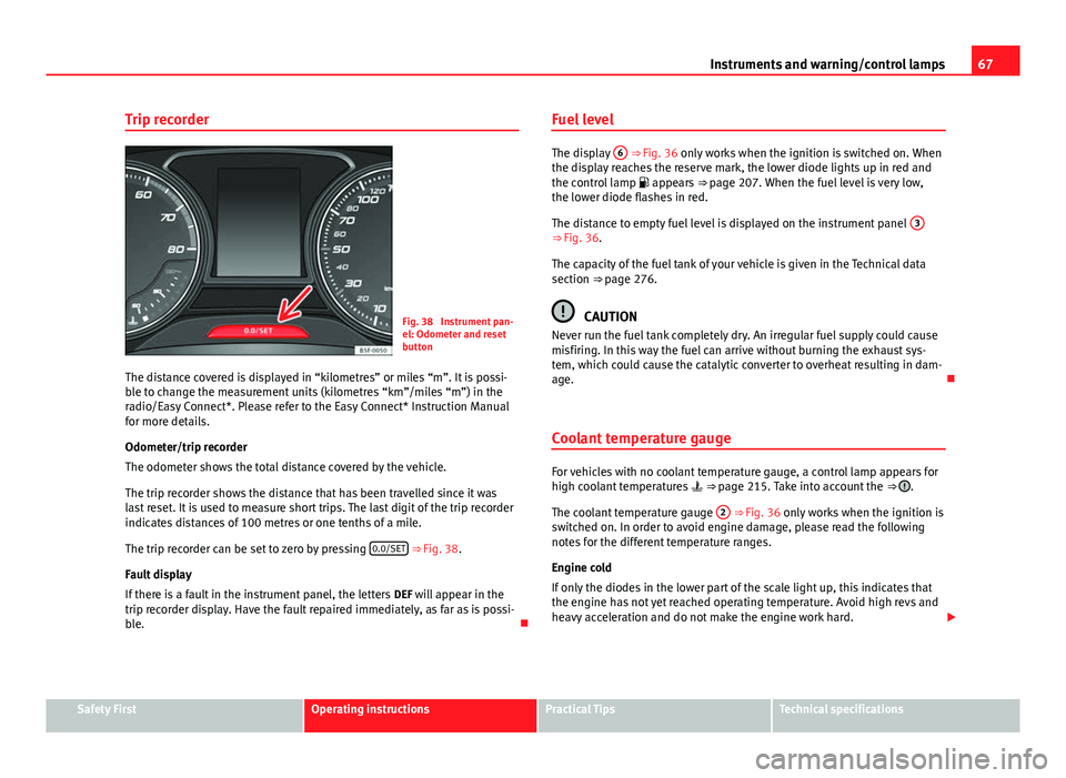
Trip recorder
Fig. 38 Instrument pan-
el: Odometer and reset
button
The distance covered is displayed in “kilometres” or miles “m”. It is possi-
ble to change the measurement units (kilometres “km”/miles “m”) in the
radio/Easy Connect*. Please refer to the Easy Connect* Instruction Manual
for more details.
Odometer/trip recorder
The odometer shows the total distance covered by the vehicle.
The trip recorder shows the distance that has been travelled since it was
last reset. It is used to measure short trips. The last digit of the trip recorder
indicates distances of 100 metres or one tenths of a mile.
The trip recorder can be set to zero by pressing 0.0/SET
⇒ Fig. 38.
Fault display
If there is a fault in the instrument panel, the letters DEF will appear in the
trip recorder display. Have the fault repaired immediately, as far as is possi-
ble. Fuel level
The display
6 ⇒ Fig. 36 only works when the ignition is switched on. When
the display reaches the reserve mark, the lower diode lights up in red and
the control lamp appears ⇒ page 207. When the fuel level is very low,
the lower diode flashes in red.
The distance to empty fuel level is displayed on the instrument panel 3
⇒ Fig. 36.
The capacity of the fuel tank of your vehicle is given in the Technical data
section ⇒ page 276.
CAUTION
Never run the fuel tank completely dry. An irregular fuel supply could cause
misfiring. In this way the fuel can arrive without burning the exhaust sys-
tem, which could cause the catalytic converter to overheat resulting in dam-
age.
Coolant temperature gauge
For vehicles with no coolant temperature gauge, a control lamp appears for
high coolant temperatures ⇒ page 215. Take into account the ⇒ .
The coolant temperature gauge 2
⇒ Fig. 36 only works when the ignition is
switched on. In order to avoid engine damage, please read the following
notes for the different temperature ranges.
Engine cold
If only the diodes in the lower part of the scale light up, this indicates that
the engine has not yet reached operating temperature. Avoid high revs and
heavy acceleration and do not make the engine work hard.
Safety FirstOperating instructionsPractical TipsTechnical specifications
Page 74 of 289
73
Driver information system
Driver information system Information system
Introduction
With the ignition switched on, it is possible to read the different functions of
the display by scrolling through the menus.
In vehicles with multifunction steering wheel, the multifunction display can
only be operated with the multifunction steering wheel buttons.
The number of menus displayed on the instrument panel will vary according
to the vehicle electronics and equipment.
A specialised workshop will be able to programme or modify additional
functions, according to the vehicle equipment. SEAT recommends visiting a
SEAT Official Service.
Some menu options can only be read when the vehicle is at a standstill.
As long as a priority 1 warning is displayed, it will not be possible to read
the menus. Some warning messages can be confirmed and made to disap-
pear with the windscreen wiper lever button or the multifunction steering
wheel button.
Additional information and warnings:
● Easy Connect system ⇒ page 79
● Driver assistance systems ⇒ page 164
● Radio or navigation system ⇒ Booklet Radio or ⇒ Booklet Navigation
system
WARNING
Any distraction may lead to an accident, with the risk of injury.
● Do not read the instrument panel display menus when driving.
Overview of the menu structure
Driving data ⇒ page 75
■ Vehicle status
■ MFD from departure
■ MFD from refuelling
■ MFD total calculation
Assist systems ⇒ table on page 75
■ Activate/deactivate Lane Assist
■ Reverse (optional)
Navigation ⇒ Booklet Navigation system Audio ⇒ Booklet Radio or ⇒ Booklet Navigation systemTelephone ⇒ Booklet Bluetooth systemVehicle ⇒ table on page 75
Safety FirstOperating instructionsPractical TipsTechnical specifications
Page 76 of 289
75
Driver information system
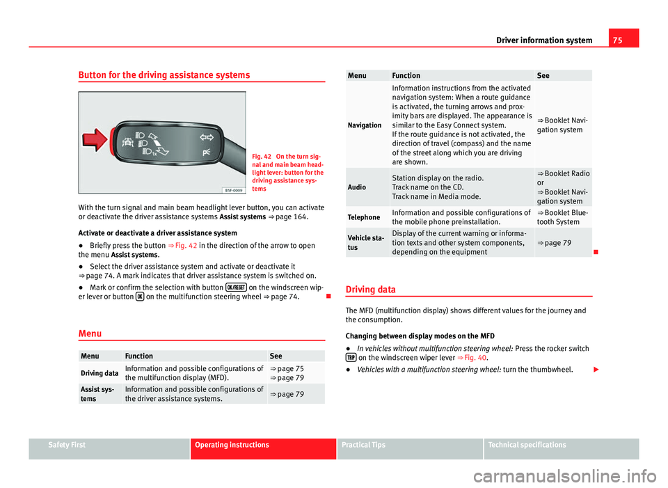
Button for the driving assistance systems
Fig. 42 On the turn sig-
nal and main beam head-
light lever: button for the
driving assistance sys-
tems
With the turn signal and main beam headlight lever button, you can activate
or deactivate the driver assistance systems Assist systems ⇒ page 164.
Activate or deactivate a driver assistance system
● Briefly press the button ⇒ Fig. 42 in the direction of the arrow to open
the menu Assist systems .
● Select the driver assistance system and activate or deactivate it
⇒ page 74. A mark indicates that driver assistance system is switched on.
● Mark or confirm the selection with button
on the windscreen wip-
er lever or button on the multifunction steering wheel
⇒ page 74.
Menu
MenuFunctionSee
Driving dataInformation and possible configurations of
the multifunction display (MFD).⇒ page 75
⇒ page 79
Assist sys-
temsInformation and possible configurations of
the driver assistance systems.⇒ page 79
MenuFunctionSee
Navigation
Information instructions from the activated
navigation system: When a route guidance
is activated, the turning arrows and prox-
imity bars are displayed. The appearance is
similar to the Easy Connect system.
If the route guidance is not activated, the
direction of travel (compass) and the name
of the street along which you are driving
are shown.
⇒ Booklet Navi-
gation system
AudioStation display on the radio.
Track name on the CD.
Track name in Media mode.⇒ Booklet Radio
or
⇒ Booklet Navi-
gation system
TelephoneInformation and possible configurations of
the mobile phone preinstallation.⇒ Booklet Blue-
tooth System
Vehicle sta-
tusDisplay of the current warning or informa-
tion texts and other system components,
depending on the equipment⇒ page 79
Driving data
The MFD (multifunction display) shows different values for the journey and
the consumption.
Changing between display modes on the MFD
● In vehicles without multifunction steering wheel: Press the rocker switch
on the windscreen wiper lever ⇒ Fig. 40.
● Vehicles with a multifunction steering wheel: turn the thumbwheel.
Safety FirstOperating instructionsPractical TipsTechnical specifications
Page 78 of 289
77
Driver information system
DisplaysMenuFunctionOil temperatureUpdated engine oil temperature digital displayCoolant tempera-
ture gaugeDigital display of the current temperature of the liquid
coolant.
Storing a speed for the speed warning
● Select the display Speed warning at --- km/h (--- mph)
● Press the button
on the windscreen wiper lever or the button on the multifunction steering wheel to store the current speed and activate
the warning.
●
If necessary, adjust the desired speed within 5 seconds using the rocker
switch
on the windscreen wiper lever or by turning the thumbwheel on
the multifunction steering wheel. Next, press the button or again
or wait several seconds. The speed is stored and the warning activated.
● To deactivate it press the button
or the button . The stored
speed is deleted.
Assist systems submenu
Assist systems
menuFunction
Lane Assist*Switching the Lane Assist system on or off ⇒ page 170.Tiredness detec-
tion*Switching the tiredness detection on or off (pause recom-
mendation) ⇒ page 173.
Personal convenience settings
When two people use a vehicle, SEAT recommends that each person always
uses their own remote control key. When the ignition is switched off, or the vehicle is locked, the convenience settings are stored and allocated to the
vehicle key
⇒ page 73.
The values of the personalised convenience settings are allocated to the ve-
hicle key in the Easy Connect system via the button
and the function
button Setup ⇒ page 79:
Vehicle settings menu
■ Time
■ Language
■ Units
Convenience settings menu ■ Door unlock (individual opening, Auto Lock)
■ Convenience handling of windows
■ Rear vision mirror adjustment
Light settings menu
■ Coming home and leaving home
■ Footwell light
■ Convenience turn signals
The stored settings are automatically activated, at the latest when the igni-
tion is switched on.
Engine oil temperature display
Vehicles without multifunction steering wheel
– To display the temperature of the engine oil, press the rocker
switch ⇒ Fig. 40 2
until the main menu appears. Enter into
Journey data . With the button 2 move to the oil temperature
gauge.
Safety FirstOperating instructionsPractical TipsTechnical specifications
Page 84 of 289

83
Introduction to the Easy Connect system*
– Press the Opening and closing
function button to open the Open-
ing and closing settings menu.
When the function button check box is activated , the function is active.
Pressing the menu button
will always take you to the last menu used.
MenuSubmenuPossible settingDescription
Opening and
Closing settings
Radio-operated
remote controlConvenience open
function.⇒ page 91
Central locking
Unlocking doors, au-
tomatic locking/un-
locking, audible
confirmation.
⇒ page 86
Any changes made using the settings menus are automatically saved on
closing those menus.
WARNING
Any distraction may lead to an accident, with the risk of injury. Operating
the Easy Connect system while driving could distract you from traffic.
Multifunction Display settings menu
–Switch the ignition on.
– Switch on the Easy Connect system.
– Press the Easy Connect button
.
– Press the Setup
function button. –
Press the Multifunction Display
function button to open the Multi-
function Display settings menu.
When the function button check box is activated , the function is active.
Pressing the menu button
will always take you to the last menu used.
MenuSubmenuPossible settingDescription
Multifunction dis-
play settings–
Current consumption, aver-
age consumption, volume
to fill up, convenience
equipments, ECOAdvice,
duration of journey, dis-
tance travelled, digital
average speed display,
speed, speeding warning,
oil temperature, coolant
temperature, restore data
“from start”, restore “total
calculation” data.
⇒ page 73
Any changes made using the settings menus are automatically saved on
closing those menus.
WARNING
Any distraction may lead to an accident, with the risk of injury. Operating
the Easy Connect system while driving could distract you from traffic.
Safety FirstOperating instructionsPractical TipsTechnical specifications
Page 188 of 289

187
Intelligent technology
If the warning lamp remains on and the driver indication appears, the power
steering could be faulty.
Do not continue driving. Seek specialist assistance. (in yellow) Steering: System fault! You may continue driving.
If the warning lamp comes on, the steering could react with more difficultly
or more sensitivity than normal. In addition, when driving in a straight line
the steering wheel may be off-centre.
Drive slowly to a specialised workshop and have the fault repaired. (in yellow) Steering lock: fault! Go to an Official Service
The electronic steering lock is malfunctioning.
Go to a specialised workshop as soon as possible and have the fault re-
paired.
WARNING
Take it immediately to a specialised workshop and have the fault re-
paired: risk of accident!
Note
If a red or yellow warning lamp come on briefly, you can continue driv-
ing. Power Management
This system helps to ensure reliable starting
The power management controls the distribution of electri-
cal energy and thus helps to ensure that there is always
enough power available to start the engine.
If a vehicle with a conventional electrical system is left parked for a long
time, the battery will gradually lose its charge because certain electrical
equipment (such as the electronic gearbox lock) continues to draw current
even when the ignition is off. In some cases there may not be enough power
available to start the engine.
Your vehicle is equipped with an intelligent power management system to
control the distribution of electrical energy. This significantly improves relia-
bility when starting the engine, and also prolongs the useful life of the bat-
tery.
The main functions incorporated in the power management system are bat-
tery diagnosis , residual current management and dynamic power manage-
ment.
Battery diagnosis
The battery diagnosis function constantly registers the condition of the bat-
tery. Sensors detect the battery voltage, battery current and battery temper-
ature. This enables the system to calculate the current power level and
charge condition of the battery.
Residual current management
The residual current management reduces power consumption while the ve-
hicle is parked. It controls the supply of power to the various electrical com-
ponents while the ignition is switched off. The system takes the battery di-
agnosis data into consideration.
Safety FirstOperating instructionsPractical TipsTechnical specifications
Page 190 of 289

189
Intelligent technology
Information recorded in the control units
Your vehicle is fitted at the factory with a series of electronic control units
responsible for the engine and gearbox management. In addition, the con-
trol units supervise the correct performance of the exhaust gas system and
the airbag systems.
Therefore, while the vehicle is being driven, these electronic control units
are continuously analysing the vehicle data. In the event of faults or devia-
tions from the theoretical values, only this data is stored. Generally, the in-
strument panel warning lamps indicate whether there are any malfunctions.
This data can only be read and analysed using special equipment.
The storing of the data allows specialised workshops to detect and repair
faults. Stored data may include:
● Important data about the engine and gearbox
● Speed
● Direction of travel
● Braking force
● Seat belt check
The vehicle control units never record conversations held by passengers in
the vehicle.
If the control unit records an accident with airbag activation, the system
may automatically send a signal. This will depend on the network operator.
Normally, transmission is only possible in areas with sufficient coverage.
Event Data Recorder
The vehicle is not fitted with an event data recorder.
An event data recorder temporarily stores the vehicle information. There-
fore, in the event of accident, it is possible to obtain detailed information
about how the accident occurred. For example, in vehicles with airbag sys-
tems, data relating to speed of impact, seat belt status, seat positions and airbag activation times may be stored. The volume of data depends on the
manufacturer.
Event data recorders can only be mounted with authorisation from the vehi-
cle owner and, in some countries, they are governed by local legislation.
Reprogramming control units
On the whole, all the data required for the component management is stor-
ed in the control units. The programming of certain convenience functions,
such as the turn signal convenience mode, individual door opening and dis-
play indications can be modified using special equipment at the workshop.
If the convenience functions are reprogrammed, the Instruction Manual in-
formation and descriptions will not coincide with the modified functions.
Therefore, SEAT recommends that any changes are recorded in the “Other
workshop notes section” of the Service Plan.
You can find out about possible reprogramming at your SEAT Official Serv-
ice.
Event recorder
In the footwell on the driver side you will find the diagnostics connection
socket for reading the event recorder. The event recorder stores operating
data and data on the status of the electronic control units. The events re-
corder should only be read and deleted by a SEAT Official Service or special-
ised workshop.
WARNING
The diagnostics connection socket must not be used for private purpo-
ses. Improper use can cause malfunctions: risk of accident!
Safety FirstOperating instructionsPractical TipsTechnical specifications
Page 195 of 289
194Trailer
Trailer
Trailer towing What do you need to bear in mind when towing a trailer?
Your vehicle may be used to tow a trailer when fitted with the correct equip-
ment.
If you wish to retrofit a towing bracket, consult ⇒ page 196.
Connectors
Your vehicle is fitted with a 12-pin connector for the electrical connection
between the trailer and the vehicle.
If the trailer has a 7-pin plug you will need to use an adapter cable. This is
available in any Technical Service.
Trailer weight/drawbar load
Never exceed the authorised trailer weight. If you do not load the trailer up
to the maximum permitted trailer weight, you can then climb correspond-
ingly steeper slopes.
The maximum trailer weights listed are only applicable for altitudes up to
1000 m above sea level. With increasing altitude the engine power and
therefore the vehicle climbing ability are impaired because of the reduced
air density. The maximum trailer weight has to be reduced accordingly. The
weight of the vehicle and trailer combination must be reduced by 10% for
every further 1000 m (or part thereof). The gross combination weight is the
actual weight of the laden vehicle plus the actual weight of the laden trailer.
When possible, operate the trailer with the maximum permitted drawbar
load on the ball joint of the towing bracket, but do not exceed the specified
limit. The figures for
trailer weights and drawbar loads that are given on the data
plate of the towing bracket are for certification purposes only. The correct
figures for your specific model, which may be lower than these figures for
the towing bracket, are given in the vehicle documentation or in ⇒ chap-
ter Technical Data.
Distributing the load
Distribute loads in the trailer so that heavy objects are as near to the axle as
possible. Loads carried in the trailer must be secured to prevent them mov-
ing.
Tyre pressure
Set tyre pressure to the maximum permissible pressure shown on the stick-
er on the inside of the fuel tank flap. Set the tyre pressure of the trailer tyres
in accordance with the trailer manufacturer's recommendations.
Exterior mirrors
Check whether you can see enough of the road behind the trailer with the
standard rear vision mirrors. If this is not the case, you should have addi-
tional exterior mirrors fitted. Both exterior mirrors should be mounted on
hinged extension brackets. Adjust the mirrors to give sufficient vision to the
rear.
WARNING
Never transport people in a trailer. This could result in fatal accidents.
Page 231 of 289

230Accessories and modifications to the vehicle
Accessories and modifications to the vehicle
Accessories, replacement parts and repairs
Always ask your dealer or specialist retailer for advice be-
fore purchasing accessories and replacement parts.
Your vehicle is designed to offer a high standard of active and passive safe-
ty. For this reason, we recommend that you ask a SEAT Official Service for
advice before fitting accessories or replacement parts. Your SEAT Official
Service has the latest information from the manufacturer and can recom-
mend accessories and replacement parts which are suitable for your re-
quirements. They can also answer any questions you might have regarding
official regulations.
We recommend you to use only SEAT accessories and Genuine SEAT parts ®
.
SEAT has tested these parts and accessories for suitability, reliability and
safety. SEAT Official Services have the necessary experience and facilities to
ensure that the parts are installed correctly and professionally.
Any retro-fitted equipment which has a direct effect on the vehicle and/or
the way it is driven (e.g. cruise control system or electronically-controlled
suspension) must be approved for use in your vehicle and bear the e mark
(the European Union's authorisation symbol).
If any additional electrical components are fitted which do not serve to con-
trol the vehicle itself (for instance a refrigerator box, laptop or ventilator fan,
etc.), these must bear the mark (manufacturer conformity declaration in
the European Union).
WARNING
Accessories, for example telephone holders or cup holders, should never
be fitted on the covers, or within the working range of the airbags. Other-
wise, there is a danger of injury if the airbag is triggered in an accident.
Technical modifications
Modifications must always be carried out according to our
specifications.
Unauthorised modifications to the electronic components, software, wiring
or data transfer in the vehicle may cause malfunctioning. Due to the way the
electronic components are linked together in networks, other indirect sys-
tems may be affected by the faults. This can seriously impair safety, lead to
excessive wear of components, and also invalidate your vehicle registration
documents.
You will appreciate that your SEAT dealership cannot be held liable for any
damage caused by modifications and/or work performed incorrectly.
We recommend that all work should be performed by a SEAT Official Service
using Genuine SEAT parts
®
.
WARNING
Incorrectly performed modifications or other work on your vehicle can
lead to malfunctions and cause accidents.
Radio transmitters and business equipment
Radio transmitters (fixed installation)
Any retrofit installations of radio transmitters in the vehicle require prior ap-
proval. SEAT generally authorises in-vehicle installations of approved types
of radio transmitters provided that: