ECO mode Seat Leon SC 2017 Owner's Guide
[x] Cancel search | Manufacturer: SEAT, Model Year: 2017, Model line: Leon SC, Model: Seat Leon SC 2017Pages: 332, PDF Size: 7.25 MB
Page 232 of 332
Operation
SEAT Drive Profile* Intr oduction SEAT Drive Profile enables the driver to
choo
se betw
een four profiles or modes, Nor-
mal , Sport , Eco and Individual , that
modify the behaviour of various vehicle func-
tions, providing different driving experiences.
In the FR and X-PERIENCE models equipped
with dynamic chassis control, the Comfort
profile is also available.
In the Leon Cupra model the four profiles are Comfort , Sport, Cupra and Individual .
The Individual profile can be configured
according to personal preferences. The other
profiles are fixed.
Description Depending on the equipment fitted in the ve-
hic
l
e,
SEAT Drive Profile can operate on the
following functions: Engine
Depending on the pr
ofile selected, the en-
gine responds more spontaneously or more
in harmony with the movements of the accel-
erator. Additionally, when Eco mode is selec-
ted, the Start-stop function is automatically
activated.
In vehicles with automatic transmission, the
gear change points are modified to position
them in lower or higher engine speed ranges.
Additionally, the Eco 1)
mode activates the In-
ertia function, enabling consumption to be
further reduced.
In manual gearbox vehicles, Eco1)
mode cau-
ses the gear change recommendation indica-
tions that appear on the instrument panel to
vary, facilitating more efficient driving.
Dynamic chassis control (DCC)
DCC continuously adapts the shock absorb-
ers to the condition of the road and current
driving conditions, according to the pre-set
programme.
In the event of a fault in the DCC, the follow-
ing message is displayed on the instrument
screen Fault: damping setting .Address
Pow
er steering becomes more robust in
Sport mode to enable a sportier driving
style. In the Leon Cupra the power steering
becomes more robust in Cupra mode.
Air conditioning
In vehicles with Climatronic, this can operate
in eco 1)
mode, especially restricting fuel con-
sumption.
Adaptive Cruise Control (ACC) 2)
According to the active driving profile, the ac-
celeration gradient of the adaptive cruise
control varies.
Electronic self-locking differential 2)
The self-locking differential adapts its behav-
iour depending on the driving profile chosen.
Normal mode or Cupra mode can be selected
to prioritise improved traction in sport driv-
ing. 1)
In the Leon Cupra model, Ec o
mode is selected
through the Individual profile.
2) Applies to the Leon Cupra model.
230
Page 233 of 332

Driver assistance systems
Setting driving mode Fig. 220
Centre console: MODE button. You can select from
Normal, Sport, Eco
and Individual .
Y ou c
an sel
ect the required mode either by
repeatedly pressing the button MODE
››› Fig. 220, or on the touch screen, in the
menu that opens when the above button is
pressed.
An icon on the Easy Connect system display
informs about the active mode.
The MODE button light remains lit up yellow
when the active mode is different to Normal.
Driving pro-
fileCharacteristics
NormalOffers a balanced driving experience,
suitable for everyday use.
Driving pro-fileCharacteristics
SportProvides a complete dynamic per-
formance in the vehicle, enabling the
user a more sporty driving style.
Eco
Places the vehicle in a particularly
low state of consumption, facilitating
a fuel-saving driving style that is re-
spectful to the environment.
Individual
Enables some configurations to be
modified by pressing the Profile
settings button. The functions that
can be adjusted depend on the
equipment fitted in the vehicle.
Conven- ience a)
It permits more relaxed and comforta-
ble driving, for example for long mo-
torway journeys. Its main characteris-
tic is the soft suspension setting
(DCC).
a)
Only for FR and X-PERIENCE models equipped with dynamic
chassis control. WARNING
When operating SEAT Drive Profile, pay atten-
tion to a l
l traffic: doing otherwise could cause
an accident. Note
● When the v ehic
le is switched off it will al-
ways store the driving profile that was selec-
ted when the ignition key was removed. Nev-
ertheless, when the engine is restarted, the engine and the gear will not restart in the set-
ting sel
ect
ed. For engine and gear to revert to
the desired position, select the correspond-
ing drive profile again or press the Easy Con-
nect system button repeatedly.
● Your speed and driving style must always
be adjus
ted to visibility, weather, and traffic
conditions.
● The Eco profile is not recommended when
to
wing a vehicle. Setting driving mode
3 App
lies to the model: Leon Cupra Fig. 221
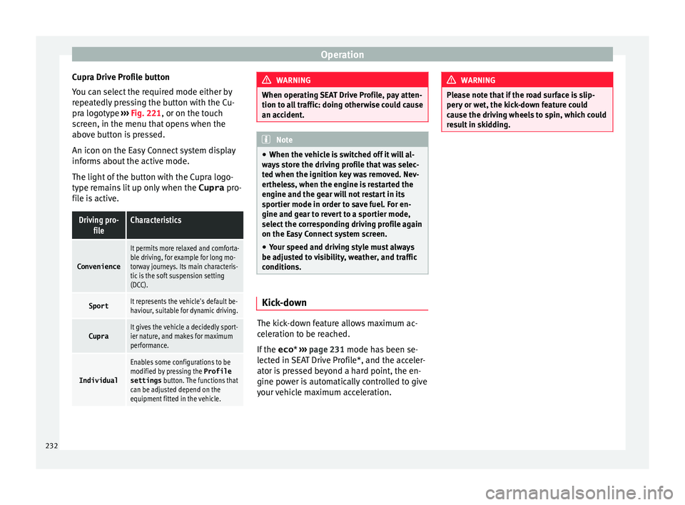
Centre console: Cupra Drive Profile
b utt
on. You can select from
Convenience, Sport,
Cupra and Individual . »
231
Technical data
Advice
Operation
Emergencies
Safety
Page 234 of 332
Operation
Cupra Drive Profile button
Y ou c
an sel
ect the required mode either by
repeatedly pressing the button with the Cu-
pra logotype ››› Fig. 221, or on the touch
screen, in the menu that opens when the
above button is pressed.
An icon on the Easy Connect system display
informs about the active mode.
The light of the button with the Cupra logo-
type remains lit up only when the Cupra pro-
file is active.
Driving pro- fileCharacteristics
Convenience
It permits more relaxed and comforta-
ble driving, for example for long mo-
torway journeys. Its main characteris-
tic is the soft suspension setting
(DCC).
SportIt represents the vehicle's default be-
haviour, suitable for dynamic driving.
CupraIt gives the vehicle a decidedly sport-
ier nature, and makes for maximum
performance.
Individual
Enables some configurations to be
modified by pressing the Profile
settings button. The functions that
can be adjusted depend on the
equipment fitted in the vehicle. WARNING
When operating SEAT Drive Profile, pay atten-
tion to a l
l traffic: doing otherwise could cause
an accident. Note
● When the v ehic
le is switched off it will al-
ways store the driving profile that was selec-
ted when the ignition key was removed. Nev-
ertheless, when the engine is restarted the
engine and the gear will not restart in its
sportier mode in order to save fuel. For en-
gine and gear to revert to a sportier mode,
select the corresponding driving profile again
on the Easy Connect system screen.
● Your speed and driving style must always
be adjus
ted to visibility, weather, and traffic
conditions. Kick-down
The kick-down feature allows maximum ac-
c
el
er
ation to be reached.
If the eco* ›››
page 231 mode has been se-
lected in SEAT Drive Profile*, and the acceler-
ator is pressed beyond a hard point, the en-
gine power is automatically controlled to give
your vehicle maximum acceleration. WARNING
Please note that if the road surface is slip-
pery or w
et, the kick-down feature could
cause the driving wheels to spin, which could
result in skidding. 232
Page 235 of 332
Driver assistance systems
Traffic sign detection system* 1)
Intr oduction The traffic sign detection system records the
st
and
ard traffic signs in front of the vehicle
with a camera located on the base of the in-
terior mirror and provides information about
speed limits and overtaking prohibitions.
Within its limitations, the system also dis-
plays additional signals, such as time-specif-
ic prohibitions, signs for vehicles towing trail-
ers ›››
page 246 or limitations that only apply
in the event of rain. Even on journeys without
signs, the system may display any applicable
speed limits.
In Germany, on motorways and vehicle roads,
besides speed limits and overtaking provi-
sions the system also displays the end of
prohibition signs. The valid speed limit at the
time in other countries is always shown. WARNING
The technology in the traffic sign detection
sys t
em cannot change the limits imposed by
the laws of physics and only works within the
system's limits. Do not let the extra conven-
ience afforded by the traffic sign detection
system tempt you into taking any risks when
driving. The system is not a replacement for
driver awareness. ●
Adapt
your speed and driving style to suit
visibility, weather, road and traffic condi-
tions.
● Poor visibility, darkness, snow, rain and fog
may
lead to the system failing to display traf-
fic signs or not displaying them correctly.
● If the camera's field of vision is dirty, cov-
ered or dam
aged, system operation may be
impaired. WARNING
The driving recommendations and traffic indi-
c ation s
shown on the traffic sign detection
system may differ from the actual current
traffic situation.
● The system may not detect or correctly
show al
l the traffic signs.
● Traffic signs and traffic regulations have
priority ov
er the recommendations and dis-
plays provided by the system. Note
In order not to compromise the system's op-
eration, p l
ease take the following points into
account:
● Regularly clean the area of vision of the
camera and k
eep it in a clean state, without
snow or ice. ●
Do not c o
ver the field of vision of the cam-
era.
● Always replace damaged or worn blades
when required t
o avoid lines on the camera's
field of vision.
● Check that the windscreen is not damaged
in the area of
the camera's field of vision. Note
● The u se of out
dated maps on the naviga-
tion system may cause the system to show
traffic signs incorrectly.
● In the waypoints mode of the navigation
syst
em, the traffic sign detection system is
only partly available. 1)
System available depending on the country.
233
Technical data
Advice
Operation
Emergencies
Safety
Page 237 of 332

Driver assistance systems
signs in front of the vehicle. After checking
and ev aluatin
g the inf
ormation from the cam-
era, the navigation system and the current
vehicle data, up to three valid traffic signs
are displayed ››› Fig. 222 B in conjunction
with their corresponding additional signs.
The sign that is currently valid for the
driver is shown in the left side of the
screen For example, a maximum speed
limit of 130 km/h (100 mph)
››› Fig. 222 A.
A sign valid only in certain circum-
stances, e.g. 100 km/h (60 mph) is
shown second, together with the addi-
tional rain sign.
If the windscreen wiper is
working while you are driving, the signal
with the additional rain sign will be
shown first, on the left, as it is the one
that is applicable at the time.
A sign valid only with restrictions, e.g.
No overtaking at certain times, will be
displayed third ››› Fig. 222 C.
Speed warning
If the system detects that the permitted
speed is exceeded, it may warn the driver
with a “gong” and visually with a message
on the dash panel display.
The speed warning can be adjusted or deacti-
vated completely in the infotainment system
using the button and the
S
ET
TINGS and
First:
Second:
Additional sign:
Third:
Driver Assistance function buttons
› ›
›
page 33. The speed is adjusted in
steps of 5 km/h (3 mph) within a range of be-
tween 0 km/h (mph) and 20 km/h (12 mph)
above the maximum speed permitted.
Trailer mode
In vehicles equipped with a towing bracket
device from the factory and a trailer that is
electrically connected to the vehicle, it is pos-
sible to activate or deactivate the display of
specific traffic signs for vehicles with trailer,
such as speed limits or overtaking prohibi-
tions. Activation or deactivation is performed
on the infotainment system using the button and the
S
ET
TINGS and
Driv er As
s
istance function buttons
› ›
›
page 33.
For trailer mode, the display of speed limits
applicable to the type of trailer or to the legal
provisions can be adjusted. The speed is ad-
justed in steps of 10 km/h (5 mph) within a
range of between 60 km/h (40 mph) and
130 km/h (80 mph). If it is adjusted to a
speed greater than that which is permitted in
the country in question for driving with a
trailer, the system automatically displays the
usual speed limits, e.g. in Germany 80 km/h
(50 mph).
If the speed warning for the trailer is deacti-
vated, the system displays the speed limits
as if there were no trailer hitched. Limited operation
The traffic s
ign detection system has certain
limitations. The following cases may lead the
system to operate with limitations or not at
all:
● In the case of poor visibility, e.g. in snow,
rain, fog or int
ense mist.
● In cases of dazzling, e.g. caused by head-
on traffic or b
y the sun.
● When driving at high speeds.
● If the camera is covered or dirty.
● If the traffic signs are out of the camera's
field of
vision.
● If the traffic signs are partially or totally
cov
ered, e.g. by trees, snow, dirt or other ve-
hicles.
● In the case of traffic signs that do not fulfil
the regu
lations.
● In the case of damaged or bent traffic
signs.
● In the c
ase of variable messages on over-
head or g
antry signs (LED-based variable traf-
fic signs or other lighting units).
● If the maps on the navigation system are
not up-to-d
ate.
● In the case of adhesives affixed to vehicles
that depict
traffic signs, e.g. speed limits on
lorries.
235
Technical data
Advice
Operation
Emergencies
Safety
Page 247 of 332

Driver assistance systems
Parking and manoeuvring with the
r e
ar a
ssist Fig. 231
Display on the Easy Connect system
s c
r
een: orientation lines. Switching the system on and off
●
The rear assist will switch on when the igni-
tion i s
on or the en
gine running, on engaging
reverse gear (manual gearbox) or on chang-
ing the selector lever to the R position (auto-
matic gearbox).
● The system switches off 8 seconds after
diseng
aging reverse gear (manual gearbox)
or removing the selector lever from the R po-
sition (automatic gearbox). The system will
also disconnect immediately after the igni-
tion is switched off. ●
The camera w
ill stop transmitting images
above the speed of 15 km/h (9 mph) with re-
verse engaged.
In combination with the Parking System Plus
››› page 237, the camera image will cease to
be transmitted immediately when reverse
gear is disengaged or when the selector lever
is moved from the R position, and the optical
information provided by the Parking Aid sys-
tem will be displayed.
Also in combination with the system, the rear
assist image can also be concealed:
● By pressing one of the Infotainment system
button
s on the display.
● OR: By pressing the miniature vehicle that
appe
ars on the left of the screen (which
switches to the full-screen mode of the Park-
ing System Plus's optical system).
If you wish to display the rear assist image
again:
● Disengage reverse, or change the selector
lever's
position, engage reverse again or
move the selector lever to position R.
● OR: Press the RVC fu
nction button1)Meaning of the orientation lines
›››
Fig. 231
Side lines: extension of the vehicle (the
approximate width of the vehicle plus the
rear view mirrors) on the road surface.
End of the side lines: the area marked in
green ends approximately 2 m behind
the vehicle on the road surface.
Intermediate line: indicates a distance of
approximately 1 m behind the vehicle on
the road surface.
Red horizontal line: indicates a safe dis-
tance of approximately 40 cm at the rear
of the vehicle on the road surface.
Parking manoeuvre
● Place the vehicle in front of the parking
spac
e and engage reverse gear (manual
gearbox) or move the selector to the R posi-
tion (automatic gearbox).
● Reverse slowly, and turn the steering wheel
so that the s
ide orientation lines lead to-
wards the parking space.
● Guide the vehicle into the parking space so
that the s
ide orientation lines run parallel to
it. 1
2
3
4
1)
WARNING: the RVC function b
utton will only be ac-
tivated and available when the reverse gear is en-
gaged or the selector lever is set to position R.
245
Technical data
Advice
Operation
Emergencies
Safety
Page 253 of 332
Towing bracket device
Trailer towing Wh at
do
you need to bear in mind
when towing a trailer? Your vehicle may be used to tow a trailer
when fitted w
ith the c
orrect equipment.
If you wish to retrofit a towing bracket, con-
sult ››› page 254.
Connectors
Your vehicle is fitted with a 13-pin connector
for the electrical connection between the
trailer and the vehicle.
If the trailer has a 7-pin plug you will need to
use an adapter cable. It is available at any
Technical Service.
Trailer weight/drawbar load
Never exceed the authorised trailer weight. If
you do not load the trailer up to the maxi-
mum permitted trailer weight, you can then
climb correspondingly steeper slopes.
The maximum trailer weights listed are only
applicable for altitudes up to 1000 m above
sea level. With increasing altitude the engine
power and therefore the vehicle climbing
ability are impaired because of the reduced
air density. The maximum trailer weight has
to be reduced accordingly. The weight of the
vehicle and trailer combination must be re- duced by 10% for every further 1000 m (or
par
t
thereof). The gross combination weight
is the actual weight of the laden vehicle plus
the actual weight of the laden trailer. When
possible, operate the trailer with the maxi-
mum permitted drawbar load on the ball joint
of the towing bracket, but do not exceed the
specified limit.
The figures for trailer weights and drawbar
loads that are given on the data plate of the
towing bracket are for certification purposes
only. The correct towing bracket figures for
your specific model, which may be lower than
these figures, are given in the vehicle docu-
mentation or on ››› page 289, Technical
specifications.
Distributing the load
Distribute loads in the trailer so that heavy
objects are as near to the axle as possible.
Loads carried in the trailer must be secured
to prevent them moving.
Tyre pressure
The maximum permissible tyre pressure val-
ues are shown on the sticker on the back of
the left front door frame. Set the tyre pres-
sure of the trailer tyres in accordance with the
trailer manufacturer's recommendations. Exterior mirrors
Check whether
you can see enough of the
road behind the trailer with the standard rear
vision mirrors. If this is not the case, you
should have additional exterior mirrors fitted.
Both exterior mirrors should be mounted on
hinged extension brackets. Adjust the mirrors
to give sufficient vision to the rear.
Tow rope
Always use a cable between the vehicle and
the trailer ››› page 252.
Trailer rear lights
The trailer's rear lights should comply with
the statutory safety regulations ››› page 252. WARNING
Never transport people in a trailer. This could
re s
ult in fatal accidents. Note
● To w
ing a trailer places additional demands
on the vehicle. We recommend additional
services between the normal inspection inter-
vals if the vehicle is used frequently for tow-
ing a trailer.
● Find out whether special regulations apply
to to
wing a trailer in your country. 251
Technical data
Advice
Operation
Emergencies
Safety
Page 269 of 332
Checking and refilling levels
Super unleaded 95 octane or normal 91 oc-
t ane u
n
leaded petrol
We recommend you use super 95 octane pet-
rol. If this is not available: normal 91 octane
petrol, with a slight decrease in power.
Super unleaded petrol with a minimum of 95
octanes
You should use super petrol with a minimum
of 95 octanes.
If super is not available, in an emergency you
may refuel with normal 91 octane petrol. In
this case only use moderate engine speeds
and a light throttle. Refuel with super as soon
as possible.
Super unleaded 98 octane or super 95 oc-
tane unleaded petrol
We recommend you use super plus 98 octane
petrol. If this is not available: super 95 oc-
tane petrol, with a slight decrease in power.
If super is not available, in an emergency you
may refuel with normal 91 octane petrol. In
this case only use moderate engine speeds
and a light throttle. Refuel with super as soon
as possible.
Petrol additives
The quality of the fuel influences the behav-
iour, power and service life of the engine.
This is why the petrol you use should carry
suitable additives already included by the petrol industry, free of metals. These addi-
tives
will help to prevent corrosion, keep the
fuel system clean and prevent deposits from
building up in the engine.
If good-quality petrol with metal-free addi-
tives is not available or engine problems
arise, the necessary additives must be added
when refuelling ››› .
Not al
l
petrol additives have been shown to
be effective. The use of unsuitable petrol ad-
ditives may cause significant damage to the
engine and the catalytic converter. Metal ad-
ditives should never be used. Metal additives
may also be contained in petrol additives for
improving anti-detonation ratings or octane
ratings ››› .
S EA
T r
ecommends “genuine Volkswagen
Group Fuel Additives for petrol engines”.
These additives can be bought at SEAT deal-
ers, where information on how to use them
can also be obtained. CAUTION
● Do not r ef
uel if the filler indicates that the
fuel contains metal. LRP ( lead replacement
petrol) fuels contain high concentrations of
metal additives. Using them may damage the
engine!
● Never refuel with fuels containing a large
proportion of
ethanol (for example, E50, E85).
This could damage the fuel system. ●
Jus t
filling one full tank of leaded fuel or
fuel containing other metal additives would
seriously impair the efficiency of the catalytic
converter.
● Only use fuel additives that have been ap-
prov
ed by SEAT. Octane boosting or anti-
knock additives may contain metal additives
that could seriously damage the engine or
the catalytic converter. These additives must not be used.
● High engine speed and full throttle can
damag
e the engine when using petrol with an
octane rating lower than the correct grade for
the engine. Note
● You m a
y use petrol with a high octane num-
ber than the one recommended for your en-
gine.
● In those countries where unleaded petrol is
not avai
lable, you may refuel with a fuel with
a low lead content. Diesel fuel
Please note the information on the inside of
the f
uel
t
ank flap.
We recommend the use of diesel fuel which
complies to European standard EN 590. If
diesel fuel which meets European standard
EN 590 is not available, the Cetane number
(CZ) must, at minimum, be 51. If the engine »
267
Technical data
Advice
Operation
Emergencies
Safety
Page 279 of 332

Checking and refilling levels
CAUTION
● Do not mi x
cleaning products recommen-
ded by SEAT with other products. This could
lead to flocculation and may block the wind-
screen washer jets.
● When topping up service fluids, make abso-
lutely c
ertain that you fill the fluids into the
correct reservoirs. Using the wrong fluids
could cause serious malfunctions and engine
damage!
● Not having windscreen wiper fluid reduces
vis
ibility through the windscreen, and leads
to loss of visibility in headlights in models
with headlight washer. Battery
Gener a
l
informationRead the additional information carefully
› ›
›
page 61.
The battery is located in the engine compart-
ment and is almost maintenance-free. It is
checked as part of the Inspection Service.
Nevertheless, check the terminals are clean
and have the correct tightening torque, espe-
cially in summer and winter.
Disconnecting the battery
The battery should only be disconnected in
exceptional cases. When the battery is dis- connected, some of the vehicle's functions
are “los
t” (››› table on page 277). These
functions will require resetting after the bat-
tery is reconnected.
Deactivate the anti-theft alarm* before you
disconnect the battery Otherwise the alarm
will be triggered.
FunctionReprogramming
One-touch function of
the electric windows››› page 138, One-touch
opening and closing*.
Remote control key
If the vehicle does not re-
spond to the key, they
should be synchronised
››› page 132.
Digital clock››› page 116.
ESC warning lampAfter driving for a few me-
tres, the warning lamp goes
out again. If the vehicle is not used for long periods
The
v
ehic
le has a system for monitoring the
current consumption when the engine is left
unused for long periods of time ››› page 201.
Some functions, such as the interior lights, or
the remote door opening, may be temporarily
disabled to prevent the battery from running
flat. These functions will come back on as
soon as the ignition is switched on and the
engine started. Winter conditions
During the w
inter, the starting power may be
reduced, and if necessary, the battery should
be charged ››› in Important safety warn-
in g
s
for handling a vehicle battery on
page 278
Important safety warnings for han-
dling a v
ehicle battery All work on batteries requires specialist
kno
wl
edg
e. Please refer to a SEAT Official
Service or a workshop specialising in batter-
ies: risk of burns or exploding battery!
The battery must not be opened. Never try to
change the fluid level of the battery. Other-
wise explosive gas is released from the bat-
tery that could cause an explosion.
Wear eye protection.
Battery acid is very corrosive and caustic. Wear
protective gloves and eye protection. In the event
of electrolyte splashes, rinse off with plenty of
water.
Fires, sparks, open flames and smoking are pro-
hibited.
The battery should only be charged in a well-ven-
tilated zone. Risk of explosion!
Keep children away from acid and batteries!»
277
Technical data
Advice
Operation
Emergencies
Safety
Page 280 of 332

Advice
WARNING
● When rep airin
g or working on the electrical
system, proceed as follows:
–1. Remove the key from the ignition. The
negative cable on the battery must be
disconnected.
– 2. When the repair is finished, reconnect
the negative pole of the battery.
● Switch off all electrical devices before re-
connecting the b
attery. Reconnect first the
positive cable and then the negative cable.
Never reverse the polarity of the connections.
This could cause an electrical fire.
● Ensure that the vent hose is always connec-
ted to the b
attery.
● Never use damaged batteries. This could
cause an e
xplosion! Replace a damaged bat-
tery immediately. CAUTION
● Never di s
connect the battery if the ignition
is switched on or if the engine is running.
This could damage the electrical system or
electronic components. Charging the battery
Terminals for charging the battery are fitted
in the en
gine comp
artment. –
Note the warnin
gs ››› in Important safety
w arnin
g
s for handling a vehicle battery on
page 278 and ››› .
– Switch off all electrical devices. Remove the
ignition k ey
.
– R
aise the bonnet ›››
page 271.
– Open the battery cover.
– Connect the charger clamps as described
to the po
sitive pole of the battery (+) and
exclusively to an earth on the bodywork
(–).
– Only use a charger which is compatible for
use with 12
V nominal voltage batteries.
The charge must not exceed a voltage of 15
V.
– Now connect the battery charger to the
power soc
ket and switch on.
– After charging the battery: switch off the
batter
y charger and disconnect the power
socket cable.
– Finally disconnect the charger cables from
the batter
y.
– Replace the battery cover correctly.
– Close the bonnet ›››
page 271.
Important: Before you charge the battery
make sure you read the manufacturer's in-
structions for using the battery charger. WARNING
Never charge a battery that has frozen: re-
pl ac
e battery! Failure to do so may lead to an
explosion. Note
Use only the terminals in the engine compart-
ment t o c
harge the battery. Replacing the battery
The new battery should have the same speci-
fic
ation
s
(amperage, load and voltage) as the
used battery.
Your vehicle is equipped with an intelligent
power management system to control the
distribution of electrical energy ›››
page 201.
The power management function ensures
that the battery is charged much more effi-
ciently than on vehicles without a power
management system. To maintain this func-
tion after replacing the battery, we recom-
mend that the replacement battery used is of
the same make and type as the original fitted
battery. To make proper use of the power
management function after the battery has
been changed, have the battery coded to the
power management mode at a specialised
workshop.
278