technical specifications Seat Mii 2013 Owner's manual
[x] Cancel search | Manufacturer: SEAT, Model Year: 2013, Model line: Mii, Model: Seat Mii 2013Pages: 306, PDF Size: 4.3 MB
Page 241 of 306
239
Practical information
If and when
Practical information
Frequently asked questions
If you suspect that the vehicle has a fault or is damaged when using it, be-
fore consulting a SEAT dealership or a specialised workshop, carefully read
the following instructions. Similarly, the terms in the alphabetical index
“Things to note” or “Checklist” may be of help.
ProblemPossible causes,
among othersPossible solution
The engine does
not start.
The vehicle battery is
flat.– Carry out the jump start
⇒ page 275.
– Charge the battery
⇒ page 193.
You are using an incor-
rect vehicle key.Use the correct key
⇒ page 28.
The fuel tank level is
insufficient.Refuel ⇒ page 171.
The vehicle cannot
be locked or un-
locked with the
key.
– Vehicle key battery is
flat.
– Too far away from
the vehicle.
– Buttons pressed out-
side the radius of
reach.– Change the battery
⇒ page 28.
– Move closer to the vehicle.
– Synchronize the vehicle
key ⇒ page 28.
– Manually lock or unlock
the vehicle ⇒ page 244.
Unusual noises.
Engine cold, City Safe-
ty Assist system, steer-
ing column electronic
lock.See entry “Noises” in the de-
tailed alphabetical index.
ProblemPossible causes,
among othersPossible solution
Handling is
strange.
Assistance systems ac-
tive.See entry “Assistance sys-
tems” in the detailed alpha-
betical index.
You are using an incor-
rect tyre pressure.Check the tyre pressure
⇒ page 210.
Damage to the wheel
trims or tyres.
Inspect wheel trims and
tyres regularly for damage
⇒ page 210 and replace
them if necessary
⇒ page 252.
Vehicle has no
jack, spare wheel
or tire mobility set
present.Equipment subject to
the vehicle.
No direct solution, depends
on the equipment. In this
case, you should contact a
SEAT Dealership
⇒ page 247.
Surface not correct-
ly illuminated.
– Headlights covered
for driving on the left-
hand side or right-
hand side.
– Headlight adjust-
ment too high.
– Faulty bulbs.
– Dipped headlights
switched off.– Cover the headlights for
driving on the left-hand side
or right-hand side
⇒ page 82.
– Adjust the headlight range
⇒ page 82.
– Change the bulbs
⇒ page 266.
– Switch on the dipped
headlights ⇒ page 82.
Vehicle diagramPrior to a journey...While drivingCare, cleaning and mainte-
nanceIf and whenTechnical specifications
Page 243 of 306
241
Practical information
In case of emergency
Introduction
Additional information and warnings:
● Braking, stopping and parking ⇒ page 134
● Emergency locking and unlocking ⇒ page 244
● Vehicle tools ⇒ page 247
● Change wheel ⇒ page 252
WARNING
A faulty vehicle in traffic represents a risk of accident for the driver and
for other road users.
● Stop the vehicle safely as soon as possible. Park the vehicle a safe
distance from surrounding traffic to lock all the doors in case of an emer-
gency. Turn on the hazard warning lights to warn other road users.
● Never leave children or disabled people alone in the vehicle if the
doors are to be locked. In case of an emergency, passengers will be trap-
ped inside the vehicle. Individuals locked in the vehicle can be exposed
to very high or very low temperatures.
Protecting yourself and securing the vehicle
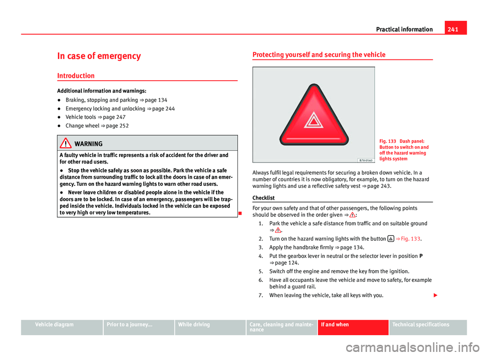
Fig. 133 Dash panel:
Button to switch on and
off the hazard warning
lights system
Always fulfil legal requirements for securing a broken down vehicle. In a
number of countries it is now obligatory, for example, to turn on the hazard
warning lights and use a reflective safety vest ⇒ page 243.
Checklist
For your own safety and that of other passengers, the following points
should be observed in the order given ⇒
:
1. Park the vehicle a safe distance from traffic and on suitable ground ⇒
.
2. Turn on the hazard warning lights with the button ⇒
Fig. 133.
3. Apply the handbrake firmly ⇒ page 134.
4. Put the gearbox lever in neutral or the selector lever in position P ⇒ page 124.
5. Switch off the engine and remove the key from the ignition.
6. Have all occupants leave the vehicle and move to safety, for example behind a guard rail.
7. When leaving the vehicle, take all keys with you.
Vehicle diagramPrior to a journey...While drivingCare, cleaning and mainte-
nanceIf and whenTechnical specifications
Page 245 of 306
243
Practical information
First aid kit, warning triangle and fire extinguishers*
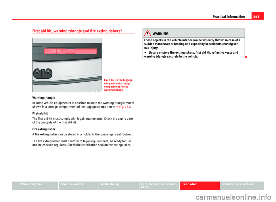
Fig. 134 In the luggage
compartment: storage
compartment for the
warning triangle
Warning triangle
In some vehicle equipment it is possible to store the warning triangle model
shown in a storage compartment of the luggage compartment ⇒ Fig. 134.
First-aid kit
The first aid kit must comply with legal requirements. Check the expiry date
of the contents of the first aid kit.
Fire extinguisher
A fire extinguisher can be stored in a holder in the passenger seat footwell.
The fire extinguisher must conform to legal requirements, be ready for use
and be checked regularly. Check the certification seal on the extinguisher.
WARNING
Loose objects in the vehicle interior can be violently thrown in case of a
sudden manoeuvre or braking and especially in accidents causing seri-
ous injury.
● Secure or store fire extinguishers, first aid kit, reflective vests and
warning triangle securely in the vehicle.
Vehicle diagramPrior to a journey...While drivingCare, cleaning and mainte-
nanceIf and whenTechnical specifications
Page 247 of 306
245
Practical information
Manually locking the passenger side door
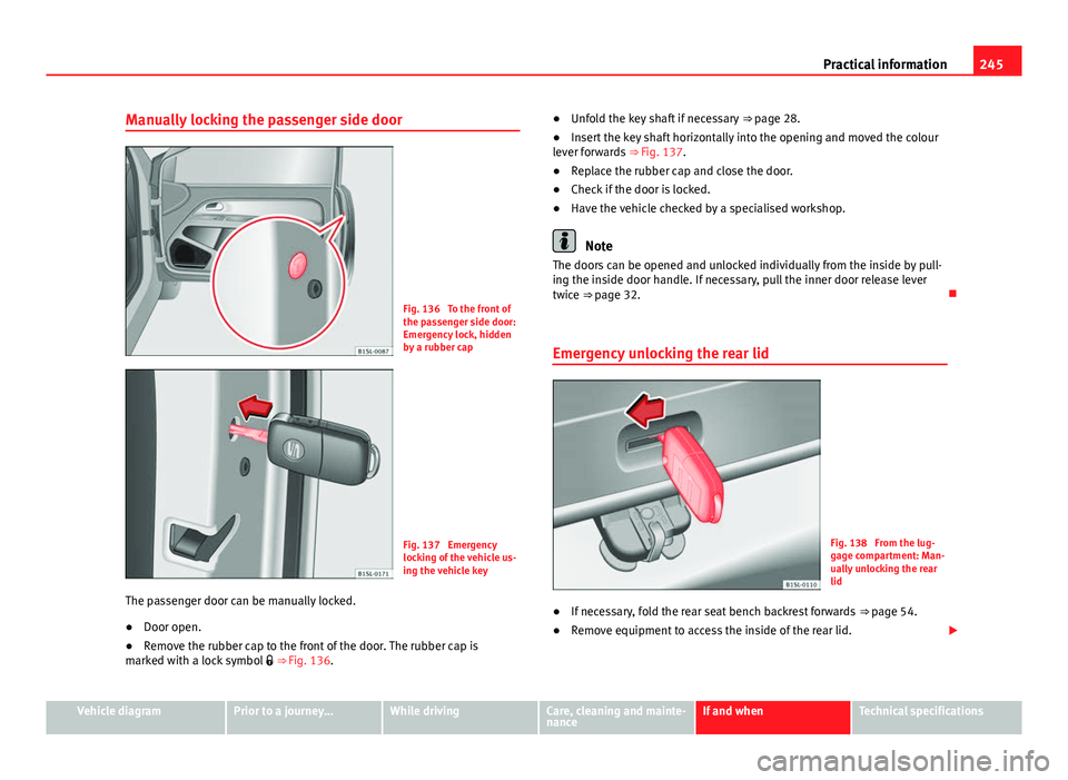
Fig. 136 To the front of
the passenger side door:
Emergency lock, hidden
by a rubber cap
Fig. 137 Emergency
locking of the vehicle us-
ing the vehicle key
The passenger door can be manually locked.
● Door open.
● Remove the rubber cap to the front of the door. The rubber cap is
marked with a lock symbol ⇒ Fig. 136. ●
Unfold the key shaft if necessary ⇒ page 28.
● Insert the key shaft horizontally into the opening and moved the colour
lever forwards ⇒ Fig. 137.
● Replace the rubber cap and close the door.
● Check if the door is locked.
● Have the vehicle checked by a specialised workshop.
Note
The doors can be opened and unlocked individually from the inside by pull-
ing the inside door handle. If necessary, pull the inner door release lever
twice ⇒ page 32.
Emergency unlocking the rear lid
Fig. 138 From the lug-
gage compartment: Man-
ually unlocking the rear
lid
● If necessary, fold the rear seat bench backrest forwards ⇒ page 54.
● Remove equipment to access the inside of the rear lid.
Vehicle diagramPrior to a journey...While drivingCare, cleaning and mainte-
nanceIf and whenTechnical specifications
Page 249 of 306
247
Practical information
Vehicle tool kit*
Introduction
When securing the vehicle in case of a breakdown, please note the legal re-
quirements for each country.
Vehicle tool kit
For vehicles with a factory-fitted spare wheel or temporary spare wheel, in
addition to winter wheels, the luggage compartment may contain additional
vehicle tools ⇒ page 247.
Additional information and warnings:
● Working in the engine compartment ⇒ page 180
● In case of emergency ⇒ page 241
● Change wheel ⇒ page 252
● Tire Mobility Set ⇒ page 258
WARNING
When the vehicle tool kit, tire mobility set and spare wheel are loose in
the interior they can be violently thrown in case of a sudden manoeuvre
or braking and especially in accidents causing serious injury.
● Ensure that the vehicle tool kit, the tire mobility set and the spare
wheel or temporary spare wheel are safely secured in the luggage com-
partment.
WARNING
Unsuitable or damaged vehicle tools can cause injury or accidents.
● Never work with inappropriate or damaged tools.
Location
Fig. 139 In the luggage
compartment: The carpet
is raised
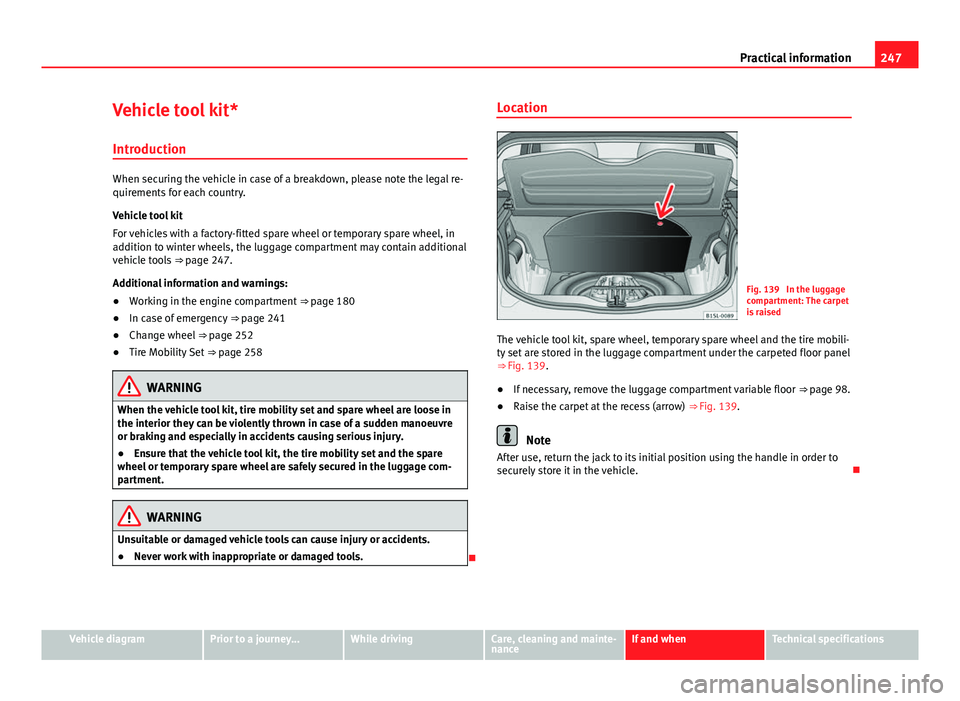
The vehicle tool kit, spare wheel, temporary spare wheel and the tire mobili-
ty set are stored in the luggage compartment under the carpeted floor panel
⇒ Fig. 139.
● If necessary, remove the luggage compartment variable floor ⇒ page 98.
● Raise the carpet at the recess (arrow) ⇒ Fig. 139.
Note
After use, return the jack to its initial position using the handle in order to
securely store it in the vehicle.
Vehicle diagramPrior to a journey...While drivingCare, cleaning and mainte-
nanceIf and whenTechnical specifications
Page 251 of 306
249
Practical information
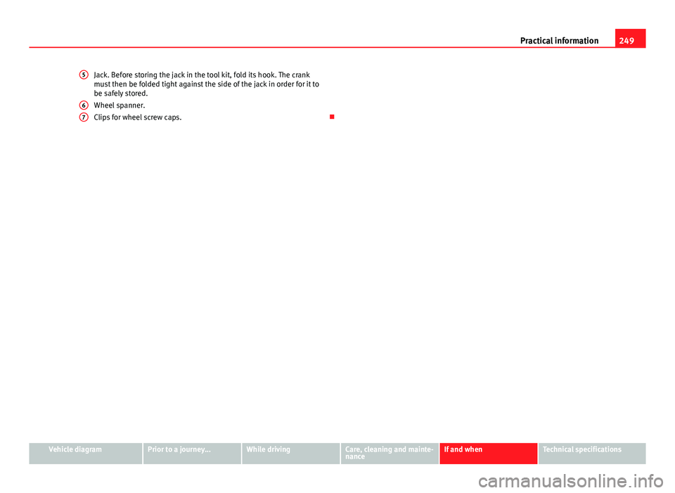
Jack. Before storing the jack in the tool kit, fold its hook. The crank
must then be folded tight against the side of the jack in order for it to
be safely stored.
Wheel spanner.
Clips for wheel screw caps.
5
67
Vehicle diagramPrior to a journey...While drivingCare, cleaning and mainte-
nanceIf and whenTechnical specifications
Page 253 of 306
251
Practical information
Full hubcaps
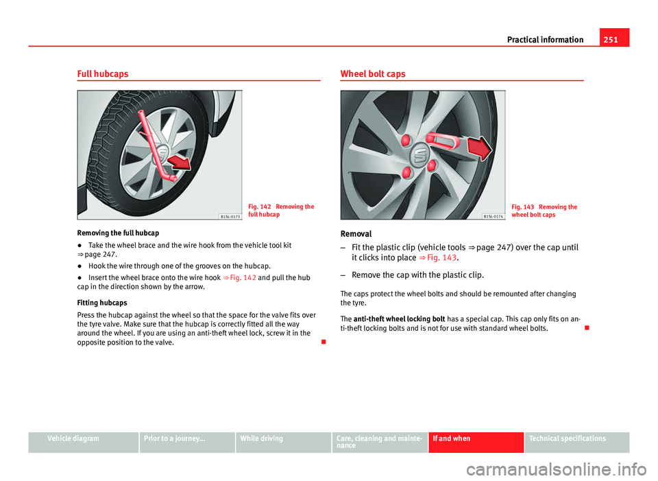
Fig. 142 Removing the
full hubcap
Removing the full hubcap
● Take the wheel brace and the wire hook from the vehicle tool kit
⇒ page 247.
● Hook the wire through one of the grooves on the hubcap.
● Insert the wheel brace onto the wire hook
⇒ Fig. 142 and pull the hub
cap in the direction shown by the arrow.
Fitting hubcaps
Press the hubcap against the wheel so that the space for the valve fits over
the tyre valve. Make sure that the hubcap is correctly fitted all the way
around the wheel. If you are using an anti-theft wheel lock, screw it in the
opposite position to the valve. Wheel bolt capsFig. 143 Removing the
wheel bolt caps
Removal
– Fit the plastic clip (vehicle tools ⇒ page 247) over the cap until
it clicks into place ⇒ Fig. 143.
– Remove the cap with the plastic clip.
The caps protect the wheel bolts and should be remounted after changing
the tyre.
The anti-theft wheel locking bolt has a special cap. This cap only fits on an-
ti-theft locking bolts and is not for use with standard wheel bolts.
Vehicle diagramPrior to a journey...While drivingCare, cleaning and mainte-
nanceIf and whenTechnical specifications
Page 255 of 306

253
Practical information
Preparations for changing a wheel
Check list
Before changing a wheel, complete the following operations in the order
given ⇒
:
1. In the event of a flat tyre, park the vehicle a safe distance from traffic and on suitable ground.
2. Apply the handbrake firmly ⇒ page 134.
3. Automatic gearbox: move the selector lever to position P
⇒ page 124.
4. Stop the engine and remove the key from the ignition ⇒ page 119.
5. Manual gearbox: Select a gear ⇒ page 124.
6. Have all vehicle occupants get out of the vehicle and wait in a safe place (for example, behind the safety barrier).
7. Chock the wheel opposite the wheel being changed with a stone or similar object.
8. If the luggage compartment is full: take the baggage out of the vehi- cle.
9. Remove the spare wheel or the temporary spare wheel and the vehi- cle tool kit from the luggage compartment.
10. Remove the wheel trims ⇒ page 250.
WARNING
Failure to follow the checklist prepared for your own safety could lead to
accidents and severe injuries.
● Always complete the operations given in the checklist and observe
the general rules of safety.
Wheel bolts
Fig. 144 Changing a
wheel: Slacken the wheel
bolts.
Fig. 145 Changing a
wheel: Tyre valve
1 and
position of anti-theft
wheel locking bolt 2
Only use the tool supplied with the vehicle to loosen the wheel bolts.
Loosen the wheel bolts only about one turn before raising the vehicle with
the jack.
Vehicle diagramPrior to a journey...While drivingCare, cleaning and mainte-
nanceIf and whenTechnical specifications
Page 257 of 306
255
Practical information
Raising the vehicle with the jack
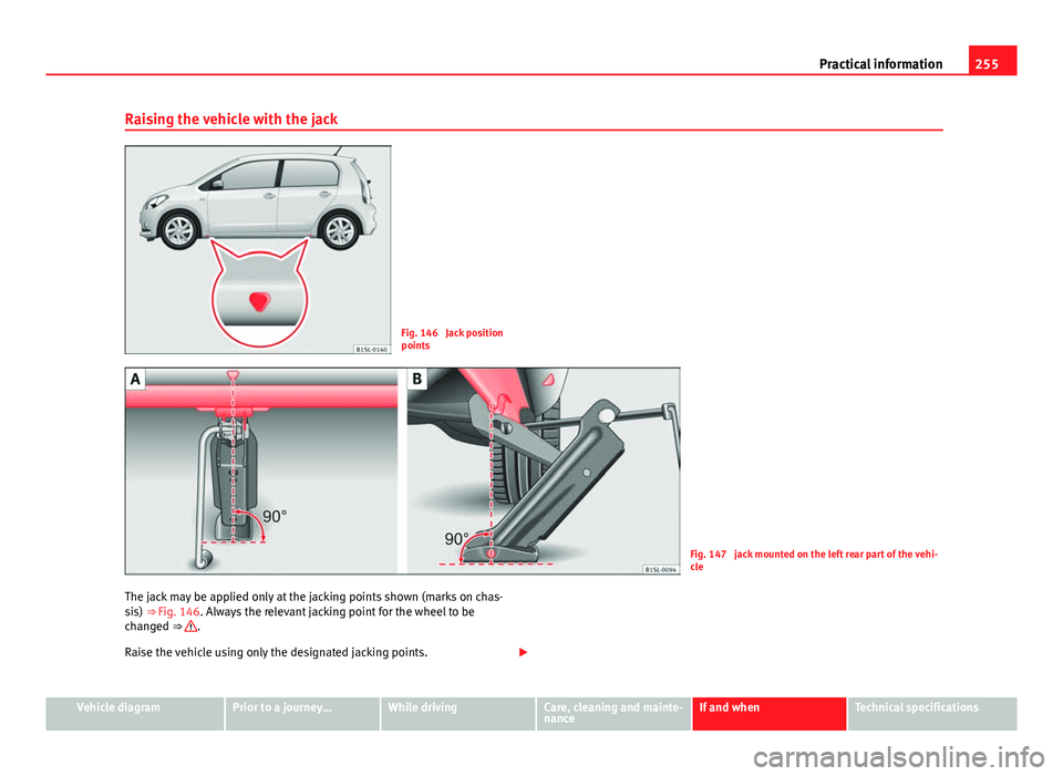
Fig. 146 Jack position
points
Fig. 147 jack mounted on the left rear part of the vehi-
cle
The jack may be applied only at the jacking points shown (marks on chas-
sis) ⇒ Fig. 146. Always the relevant jacking point for the wheel to be
changed ⇒
.
Raise the vehicle using only the designated jacking points.
Vehicle diagramPrior to a journey...While drivingCare, cleaning and mainte-
nanceIf and whenTechnical specifications
Page 259 of 306
257
Practical information
Changing a wheel
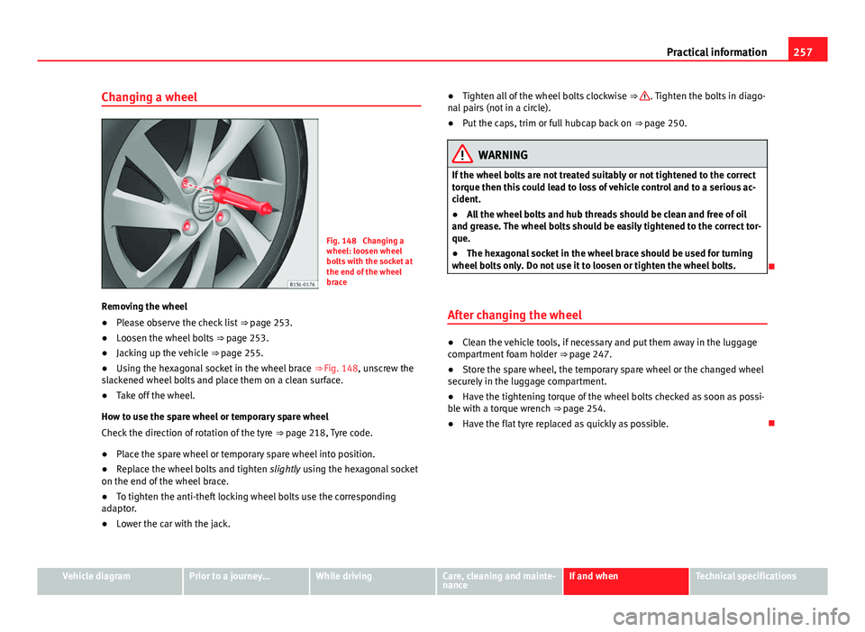
Fig. 148 Changing a
wheel: loosen wheel
bolts with the socket at
the end of the wheel
brace
Removing the wheel
● Please observe the check list ⇒ page 253.
● Loosen the wheel bolts ⇒ page 253.
● Jacking up the vehicle ⇒ page 255.
● Using the hexagonal socket in the wheel brace ⇒ Fig. 148, unscrew the
slackened wheel bolts and place them on a clean surface.
● Take off the wheel.
How to use the spare wheel or temporary spare wheel
Check the direction of rotation of the tyre ⇒ page 218, Tyre code.
● Place the spare wheel or temporary spare wheel into position.
● Replace the wheel bolts and tighten slightly using the hexagonal socket
on the end of the wheel brace.
● To tighten the anti-theft locking wheel bolts use the corresponding
adaptor.
● Lower the car with the jack. ●
Tighten all of the wheel bolts clockwise ⇒
. Tighten the bolts in diago-
nal pairs (not in a circle).
● Put the caps, trim or full hubcap back on ⇒ page 250.
WARNING
If the wheel bolts are not treated suitably or not tightened to the correct
torque then this could lead to loss of vehicle control and to a serious ac-
cident.
● All the wheel bolts and hub threads should be clean and free of oil
and grease. The wheel bolts should be easily tightened to the correct tor-
que.
● The hexagonal socket in the wheel brace should be used for turning
wheel bolts only. Do not use it to loosen or tighten the wheel bolts.
After changing the wheel
● Clean the vehicle tools, if necessary and put them away in the luggage
compartment foam holder ⇒ page 247.
● Store the spare wheel, the temporary spare wheel or the changed wheel
securely in the luggage compartment.
● Have the tightening torque of the wheel bolts checked as soon as possi-
ble with a torque wrench ⇒ page 254.
● Have the flat tyre replaced as quickly as possible.
Vehicle diagramPrior to a journey...While drivingCare, cleaning and mainte-
nanceIf and whenTechnical specifications