start stop button Seat Mii 2016 Owner's manual
[x] Cancel search | Manufacturer: SEAT, Model Year: 2016, Model line: Mii, Model: Seat Mii 2016Pages: 232, PDF Size: 4.9 MB
Page 89 of 232
General instrument panel
Operation
Gener a
l
instrument panel
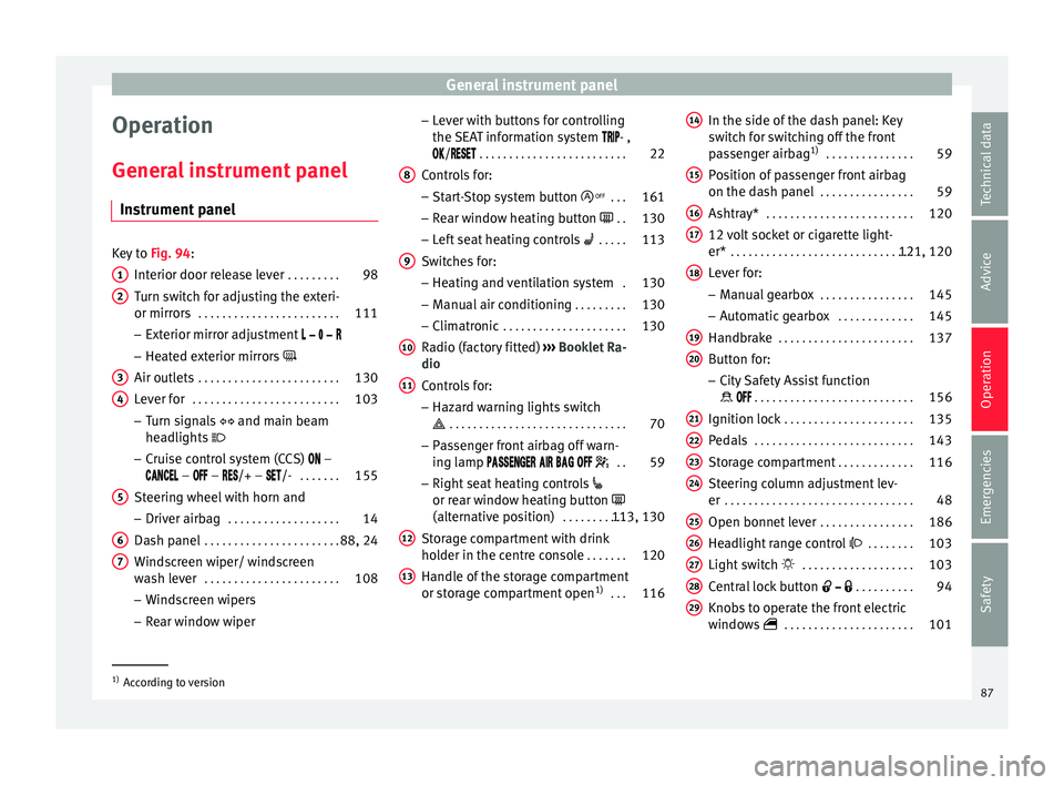
Instrument panel Key to
Fig. 94:
Interior door r el
ease lever . . . . . . . . . 98
Turn switch for adjusting the exteri-
or mirrors . . . . . . . . . . . . . . . . . . . . . . . . 111
– Exterior mirr or a
djustment
– Heated exterior mirrors
Air outlets . . . . . . . . . . . . . . . . . . . . . . . . 130
Lever for . . . . . . . . . . . . . . . . . . . . . . . . . 103
– Turn sign
als and main beam
headlights
– Cruise control system (CCS) –
– – /+ – /- . . . . . . .155
Steering wheel with horn and – Driver airb ag . . . . . . . . . . . . . . . . . . . 14
Da
sh panel . . . . . . . . . . . . . . . . . . . . . . . 88, 24
Windscreen wiper/ windscreen
wash l
ever . . . . . . . . . . . . . . . . . . . . . . . 108
– Wind s
creen wipers
– Rear window wiper
1 2
3
4
5
6
7 –
Lev
er w
ith buttons for controlling
the SEAT information system - ,
/ . . . . . . . . . . . . . . . . . . . . . . . . . 22
Controls for:
– Start
-Stop system button . . .161
– Rear w
indow heating button . .130
– Left
seat heating controls . . . . . 113
Switches for: – Heating and
ventilation system .130
– Manual air c
onditioning . . . . . . . . . 130
– Clim atr
onic . . . . . . . . . . . . . . . . . . . . . 130
Radio (factory fitted) ›››
Booklet Ra-
dio
Controls for:
– Hazard warning lights switch
. . . . . . . . . . . . . . . . . . . . . . . . . . . . . . 70
– Pa s
senger front airbag off warn-
ing lamp . .59
– Right seat
heating controls
or rear window heating button
(alternative position) . . . . . . . . . . .113, 130
Storage compartment with drink
hol der in the c
entre console . . . . . . .120
Handle of the storage compartment
or stor
age compartment open 1)
. . . 116
8 9
10
11
12
13 In the side of the dash panel: Key
sw
it
c
h for switching off the front
passenger airbag 1)
. . . . . . . . . . . . . . . 59
Position of passenger front airbag
on the dash p
anel . . . . . . . . . . . . . . . . 59
Ashtray* . . . . . . . . . . . . . . . . . . . . . . . . . 120
12 volt socket or cigarette light-
er* . . . . . . . . . . . . . . . . . . . . . . . . . . . . . . . 121, 120
Lever for:
– Manual g
earbox . . . . . . . . . . . . . . . . 145
– Autom atic
gearbox . . . . . . . . . . . . . 145
Handbrake . . . . . . . . . . . . . . . . . . . . . . . 137
Button for:
– City
Safety Assist function
. . . . . . . . . . . . . . . . . . . . . . . . . . . 156
Ignition lock . . . . . . . . . . . . . . . . . . . . . . 135
Pedals . . . . . . . . . . . . . . . . . . . . . . . . . . . 143
Storage compartment . . . . . . . . . . . . .116
Steering column adjustment lev-
er . . . . . . . . . . . . . . . . . . . . . . . . . . . . . . . . 48
Open bonnet lever . . . . . . . . . . . . . . . . 186
Headlight range control . . . . . . . . 103
Light switch . . . . . . . . . . . . . . . . . . . 103
Central lock button . . . . . . . . . .94
Knobs to operate the front electric
window
s . . . . . . . . . . . . . . . . . . . . . . 101 14
15
16
17
18
19
20
21
22
23
24
25
26
27
28
29
1)
According to version
87
Technical data
Advice
Operation
Emergencies
Safety
Page 91 of 232
General instrument panel
bottom buttons of the rocker
sw it
c
h ›››
Fig. 33
B .
– Pr e
s
s the button to change
the hour , so th
at
it is flashing.
– To continue setting the time,
press button 0.0/SET . Hold button
do wn t
o s
croll through the num-
bers quickly.
– Press the button again to
c h
an
ge the minutes, so that it
flashes.
– To continue setting the time,
press button 0.0/SET . Hold button
do wn t
o s
croll through the num-
bers quickly.
– Press button again to end the
c loc
k
setting. CAUTION
● When the engine i s
cold, avoid high revs
and heavy acceleration and do not make the
engine work hard.
● To prevent damage to the engine, the revo-
lution count
er needle should only remain in
the red zone for a short period of time. For the sake of the environment
Changing up a gear in time reduces fuel con-
sumption and noi se. Indications on the display
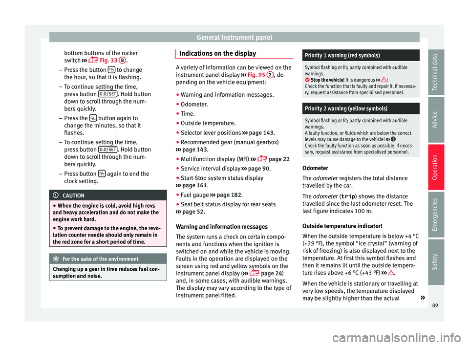
A variety of information can be viewed on the
ins
trument
panel display ››› Fig. 95 2 , de-
pending on the v
ehicle equipment:
● Warning and information messages.
● Odometer.
● Time.
● Outside temperature.
● Selector lever positions ›››
page 143.
● Recommended gear (manual gearbox)
›› ›
page 143.
● Multifunction display (MFI) ›››
page 22
● Service interval display ›››
page 90 .
● Start-Stop system status display
›››
page 161.
● Fuel gauge ›››
page 182.
● Seat belt status display for rear seats
›››
page 52.
Warning and information messages
The system runs a check on certain compo-
nents and functions when the ignition is
switched on and while the vehicle is moving.
Faults in the operation are displayed on the
screen using red and yellow symbols on the
instrument panel display ( ›››
page 24)
and, in some cases, with audible warnings.
The display may vary according to the type of
instrument panel fitted.
Priority 1 warning (red symbols)
Symbol flashing or lit; partly combined with audible
warnings.
Stop the vehicle! It is dangerous ››› !
Check the function that is faulty and repair it. If necessa-
ry, request assistance from specialised personnel.
Priority 2 warning (yellow symbols)
Symbol flashing or lit; partly combined with audible
warnings.
A faulty function, or fluids which are below the correct
levels may cause damage to the vehicle! ›››
Check the faulty function as soon as possible. If neces-
sary, request assistance from specialised personnel. Odometer
The odomet
er
r
egisters the total distance
travelled by the car.
The odometer (trip ) shows the distance
travelled since the last odometer reset. The
last figure indicates 100 m.
Outside temperature indicator!
When the outside temperature is below +4 °C
(+39 °F), the symbol “ice crystal” (warning of
risk of freezing) is also displayed next to the
temperature. At first this symbol flashes and
then it remains lit until the outside tempera-
ture rises above +6 °C (+43 °F) ››› .
When the v
ehic
le is stationary or travelling at
very low speeds, the temperature displayed
may be slightly higher than the actual »
89
Technical data
Advice
Operation
Emergencies
Safety
Page 124 of 232
Operation
sockets in order to charge the vehicle's
batt
er
y.
● Only use accessories with approved elec-
tromagnetic
compatibility according to cur-
rent regulations.
● To avoid damage due to voltage variations,
switc
h off all devices connected to the 12 V
socket before switching the ignition on or off
and before starting the engine.
● Never connect an appliance to the 12 volt
power soc
ket that consumes more than the
power indicated in watts. Exceeding the max-
imum power absorption could damage the ve-
hicle's electrical system. For the sake of the environment
Do not leave the engine running when the ve-
hicl e i
s at a standstill. Note
● Us in
g devices with the engine stopped and
the ignition switched on will drain the bat-
tery.
● Unshielded equipment can cause interfer-
ence on the ra
dio equipment and the vehi-
cle's electrical system.
● Interference can occur on the radio's AM
wave
band if electrical appliances are used
near the aerial. Portable Smartphone base
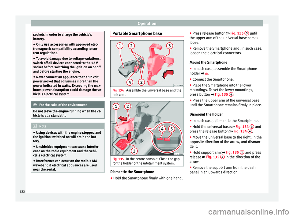
Fig. 134
Assemble the universal base and the
link arm. Fig. 135
In the centre console: Close the gap
f or the ho
l
der of the infotainment system. Dismantle the Smartphone
● Hold the Smartphone firmly with one hand. ●
Pr e
s
s release button ››› Fig. 135 5 until
the up per arm of
the u
niversal base comes
loose.
● Remove the Smartphone and, in such case,
loosen the electric
al connectors.
Mount the Smartphone
● In such case, assemble the Smartphone
holder ›
›› .
● Connect the Smartphone.
● Place the Smartphone into the lower
mou ntin
g
s. To set the lower mountings,
press button ››› Fig. 135 4 .
● Press the upper arm of the universal base
u nti
l
the Smartphone remains firmly in place.
Dismount the holder
● In such case, dismantle the Smartphone.
● Hold the universal base ›››
Fig. 134 3 and
pr e
s
s the release button ››› Fig. 134 4 .
● Move the universal base to the right, in the
op po
s
ite direction of the arrow, and disman-
tle it.
● Hold support arm ›››
Fig. 135 1 and press
r el
e
ase ››› Fig. 135 4 in the direction of the
arr o
w
.
● Remove the support arm from the dash
panel in an up
wards direction.
122
Page 137 of 232
Driving
Stopping and starting the en-
gine Sw it
c
hing on the ignition and starting
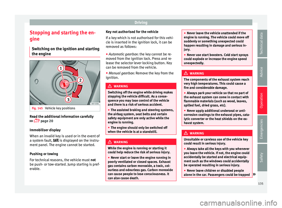
the engine Fig. 145
Vehicle key positions Read the additional information carefully
› ›
›
page 20
Immobiliser display
When an invalid key is used or in the event of
a system fault, is displayed on the instru-
ment panel. The engine cannot be started.
Pushing or towing
For technical reasons, the vehicle must not
be push- or tow-started. Jump starting is pref-
erable. Key not authorised for the vehicle
If a key
which is not authorised for this vehi-
cle is inserted in the ignition lock, it can be
removed as follows:
● Automatic gearbox : the key c
annot be re-
moved from the ignition lock. Press and re-
lease the selector lever locking button. Key
can be removed from the vehicle.
● Manual gearbox: Remov
e the key from the
ignition. WARNING
Switching off the engine while driving makes
st op
ping the vehicle difficult. As a conse-
quence you may lose control of the vehicle
and there is a risk of serious accident.
● The assisted braking and steering systems,
the airbag sys
tem, seat belts and certain
safety equipment are only active while the
engine is running.
● The engine should only be switched off
when the vehic
le is at a standstill. WARNING
While the engine is running or starting it
cou l
d help reduce the risk of serious injury.
● Never start or leave the engine running in
poorly v
entilated or closed spaces. Exhaust
gas contains carbon monoxide, a toxic, col-
ourless and odourless gas. Carbon monoxide
can cause people to lose consciousness. It
can also cause death. ●
Never l e
ave the vehicle unattended if the
engine is running. The vehicle could move off
suddenly or something unexpected could
happen resulting in damage and serious in-
jury.
● Never use start boosters. Cold start sprays
coul
d explode or increase the engine speed
unexpectedly. WARNING
The components of the exhaust system reach
v er y
high temperatures. This could cause a
fire and considerable damage.
● Always park your vehicle so that no part of
the exhau
st system can come in contact with
flammable materials (such as wood, leaves,
spilled fuel, dried grass, etc).
● Never apply additional underseal or anti-
corro
sion coatings to the exhaust pipes, cata-
lytic converter or the heat shields on the ex-
haust system. WARNING
Unsuitable or careless use of the vehicle key
cou l
d result in serious injury.
● Always take all the keys with you whenever
you le
ave the vehicle. If not, the engine could
accidentally be started and electrical equip-
ment such as the windows could accidentally
be operated resulting in serious injury.
● Never leave children or disabled people
alone in the car
. Passengers could be trapped » 135
Technical data
Advice
Operation
Emergencies
Safety
Page 138 of 232
Operation
in the car in an emergency and not be able to
get
themselv
es to safety. For example, de-
pending on the time of the year, tempera-
tures inside a locked and closed vehicle can
be extremely high or extremely low resulting
in serious injuries and illness or even death,
particularly for young children.
● Never remove the key from the ignition if
the vehic
le is in motion. The steering may
lock and it will not be possible to turn the
steering wheel. CAUTION
● An attempt t
o start the engine while driving
or starting the engine immediately after turn-
ing it off can cause damage to the engine or
starter motor.
● When the engine is cold, avoid high revs
and heavy ac
celeration and do not make the
engine work hard.
● Do not push or tow start the engine. Un-
burnt f
uel could damage the catalytic con-
verter. For the sake of the environment
Do not warm the engine at idle speed; start
drivin g immedi
ately if the visibility is OK.
This helps the engine reach operating tem-
perature faster and reduces emissions. Note
● If the k ey
is left in the ignition lock with the
engine off for long periods, the vehicle bat-
tery will run flat.
● For automatic gearbox vehicles, the key can
only be r
emoved from the ignition lock if the
gear selector lever is in position N. In this
case, press and release the selector lever
locking button.
● Electrical devices with a high power con-
sumption are sw
itched off temporarily when
the engine starts.
● When the engine is started cold, there may
be stron
g vibrations for a few moments for
technical reasons. This is quite normal, and
no cause for concern.
● Natural gas engines always start up with
petrol, a
s a certain operating temperature is
required for running with gas. Once the re-
quired operating temperature is reached, the
engine will change to operate with natural
gas. Stopping the engine
Switching off the engine
– Stop the vehicle ››
›
.
– Turn the ignition key to position 1 ›››
Fig. 145. Engaging the steering wheel lock
In
v
ehic
les with automatic gearbox, the igni-
tion key can only be removed when the selec-
tor lever is in position N.
– Remove the key from the ignition in posi-
tion 1
› ››
Fig. 145
›
›› .
– Turn the steering wheel until you hear it en-
gag
e.
P
ossible vehicle theft is prevented with the
steering lock engaged. WARNING
Never switch off the engine while the vehicle
is mo
ving. You may lose control of the vehicle
and there is a risk of serious accident.
● The airbags and belt tensioners do not
work when the ignition i
s switched off.
● The brake servo does not work with the en-
gine off. T
o stop, the brake pedal must be
pressed with more force.
● As the power steering does not work if the
engine is
not running, you will need more
strength to steer than normally.
● If the key is removed from the ignition, the
steerin
g may lock and it will not be possible
to steer the vehicle. 136
Page 163 of 232
Driver assistance systems
WARNING
● If y
ou do not start the vehicle immediately
after taking your foot off the brake pedal, the
vehicle may start to roll back under certain
conditions. Depress the brake pedal or use
the hand brake immediately.
● If the engine stalls, depress the brake ped-
al or u
se the hand brake immediately.
● When following a line of traffic uphill, if you
want t
o prevent the vehicle from rolling back
accidentally when starting off, hold the brake
pedal down for a few seconds before starting
off. Note
The Official Service or a specialist workshop
can t el
l you if your vehicle is equipped with
this system. Start-Stop System
C ontr
o
l lamps
It lights up
The Start-Stop system is enabled.
It lights up
The Start-Stop sys-
tem is enabled but
the engine cannot
be automatically
stopped.
Contact a specialised workshop.
It lights up
The Start-Stop sys-
tem cannot start the
engine.Start the engine by hand using
the vehicle's key
››› page 135.
There is a fault in the
alternator.››› page 196
Flashes
The Start-Stop sys-
tem is not available.Contact a specialised workshop.
Some warning and control lamps will light up
briefly
when the ignition i
s
switched on to
check certain functions. They will switch off
after a few seconds. WARNING
Observe the safety warnings ›››
in On the
ins trument
panel on page 26. Start-Stop system
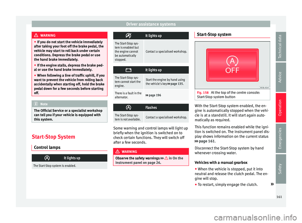
Fig. 158
At the top of the centre console:
St ar
t
-Stop system button With the Start-Stop system enabled, the en-
gine i
s
aut
omatically stopped when the vehi-
cle is at a standstill. It will start again auto-
matically as required.
This function remains enabled while the igni-
tion is switched on. The instrument panel dis-
play shows information on the current status
››› page 161.
Disconnect the Start-Stop system by hand
whenever crossing water.
Vehicles with a manual gearbox
● When the vehicle is stopped, put it into
neutral and r
elease the clutch pedal. The en-
gine will stop.
● To restart, simply engage the clutch. »
161
Technical data
Advice
Operation
Emergencies
Safety
Page 164 of 232
Operation
Vehicles with an automatic gearbox
● When the vehicle is at a standstill, depress
the br ak
e or k
eep it pressed down. The en-
gine switches off.
● The engine will start again as soon as you
rele
ase the brake pedal.
● With the selector lever set to position N,
the engine wi
ll not start until a range of gears
is selected or the accelerator pedal is de-
pressed.
Important conditions for the engine to stop
automatically
● The driver's seat belt must be fastened.
● The driver door must be closed.
● The bonnet must be closed.
● The engine must have reached a minimum
temperat
ure.
● The vehicle must have moved since the last
time the engine wa
s stopped.
● The vehicle's battery must be sufficiently
char
ged.
● The battery temperature must not be too
low or too high.
● The
vehicle must not be on a very steep
slope. Condition
s for the engine to restart automat-
ical
ly
The engine can be automatically restarted in
the following cases:
● If the vehicle starts to moves.
● If the battery voltage drops.
Conditions
requiring engine start-up using
the key
The engine has to be manually started in the
following cases:
● If the driver unbuckles his/her seat belt.
● If the driver door is opened.
● If the bonnet is opened.
Switc
hing the Start-Stop system on and off
● Press the button situat
ed in the centre
console ››› Fig. 158.
● The button will light up when the Start-Stop
syst
em is switched off.
The engine will start immediately if the vehi-
cle is in Stop mode when the system is
switched off by hand. WARNING
The smart technology included in the hill
hol d c
annot change the laws of physics. Do
not let the extra convenience afforded by the hill hold tempt you into taking any risks
when drivin
g.
● An
y accidental movement of the vehicle
coul
d result in serious injury.
● The hill hold is not a replacement for driver
awar
eness.
● Adjust your speed and driving style to visi-
bility
, weather, road and traffic conditions.
● The hill hold cannot always keep the vehi-
cle at
a standstill on a slope or brake suffi-
ciently when travelling downhill (e.g. on slip-
pery or frozen surfaces). WARNING
The brake servo and the electromechanical
st eerin
g do not work when the engine is
switched off.
● The vehicle must never be allowed to move
with the engine sw
itched off.
● Disconnect the Start-Stop system before
workin
g in the engine compartment. CAUTION
The vehicle's battery could be damaged if the
vehic l
e is used for long periods at very high
outside temperatures. Note
In some cases, it may be necessary to start
the engine b y
hand using the key. Refer to162
Page 222 of 232
Index
tyre pressure . . . . . . . . . . . . . . . . . . . . . . . . . . . 203
w ind
s
creen washer bottle . . . . . . . . . . . . . . . . 173
Driving safety . . . . . . . . . . . . . . . . . . . . . . . . . . . . . 47
Driving through water . . . . . . . . . . . . . . . . . . . . . 153
Driving tips for a loaded vehicle . . . . . . . . . . . . . . . . . . . . . 114
Duplicate keys . . . . . . . . . . . . . . . . . . . . . . . . . . . . 92
Dust filter . . . . . . . . . . . . . . . . . . . . . . . . . . . . . . . 133
Dynamic headlight range control . . . . . . . . . . . . 107
E E10 see Ethanol (fuel) . . . . . . . . . . . . . . . . . . . . . . . 181
EDL see Electronic differential lock . . . . . . . . . . . . . 139
EDS see "Brake assist systems" . . . . . . . . . . . . . . . 140
Electric windows . . . . . . . . . . . . . . . . . . . . . . . . . . . . . . . 11
Electrical devices . . . . . . . . . . . . . . . . . . . . 121, 122
Electric windows . . . . . . . . . . . . . . . . . . . . . . . . . . . 11 buttons . . . . . . . . . . . . . . . . . . . . . . . . . . . . . . . 101
closing . . . . . . . . . . . . . . . . . . . . . . . . . . . . . . . . 101
opening . . . . . . . . . . . . . . . . . . . . . . . . . . . . . . . 101
see Windows . . . . . . . . . . . . . . . . . . . . . . . . . . . 101
Electronic differential lock . . . . . . . . . . . . . . . . . . 139
Electronic immobiliser . . . . . . . . . . . . . . . . . . . . . 137 operating fault . . . . . . . . . . . . . . . . . . . . . . . . . 135
Electronic Stability Control (ESC) . . . . . . . . . . . . 139
Emergencies . . . . . . . . . . . . . . . . . . . . . . . . . . . . . . 70 bulbs . . . . . . . . . . . . . . . . . . . . . . . . . . . . . . . . . . 35
changing a wheel . . . . . . . . . . . . . . . . . . . . . . . . 36
emergency towing of the vehicle . . . . . . . . . . . . 42
fire extinguishers . . . . . . . . . . . . . . . . . . . . . . . . 70
first aid kit . . . . . . . . . . . . . . . . . . . . . . . . . . . . . . 70
fuses . . . . . . . . . . . . . . . . . . . . . . . . . . . . . . . . . . 34
hazard warning lights . . . . . . . . . . . . . . . . . . . 106 Jump leads . . . . . . . . . . . . . . . . . . . . . . . . . . . . . 43
punct
ure . . . . . . . . . . . . . . . . . . . . . . . . . . . . . . . 35
replacing a blown fuse . . . . . . . . . . . . . . . . . . . . 34
vehicle tool kit . . . . . . . . . . . . . . . . . . . . . . . . . . 70
warning triangle . . . . . . . . . . . . . . . . . . . . . . . . . 70
Emergency closing or opening driver door . . . . . . . . . . . . . . . . . . . . . . . . . . . . . . 8
passenger door . . . . . . . . . . . . . . . . . . . . . . . . . . . 9
Emergency locking and unlocking . . . . . . . . . . . . 77
Emergency unlocking boot hatch . . . . . . . . . . . . . . . . . . . . . . . . . . . . . . 10
Emergency unlocking the boot hatch boot hatch . . . . . . . . . . . . . . . . . . . . . . . . . . . . . . 10
Emission control system control and warning lamps . . . . . . . . . . . . . . . 151
Emissions data . . . . . . . . . . . . . . . . . . . . . . . . . . . 210
Engine assisted starting . . . . . . . . . . . . . . . . . . . . . . . . . 43
noises . . . . . . . . . . . . . . . . . . . . . . . . . . . . . . . . 136
running in . . . . . . . . . . . . . . . . . . . . . . . . . . . . . 148
start-Stop system . . . . . . . . . . . . . . . . . . . . . . . 161
Engine and ignition . . . . . . . . . . . . . . . . . . . . . . . 135 12 Volt sockets . . . . . . . . . . . . . . . . . . . . . . . . . 122
ignition lock . . . . . . . . . . . . . . . . . . . . . . . . . . . 135
immobiliser . . . . . . . . . . . . . . . . . . . . . . . . . . . . 137
starting the engine . . . . . . . . . . . . . . . . . . . . . . 135
stopping the engine . . . . . . . . . . . . . . . . . . . . . 136
unauthorised vehicle key . . . . . . . . . . . . . . . . . 135
Engine compartment . . . . . . . . . . . . . . . . . . 10, 186 battery . . . . . . . . . . . . . . . . . . . . . . . . . . . . 33, 196
brake fluid . . . . . . . . . . . . . . . . . . . . . . . . . 33, 194
coolant . . . . . . . . . . . . . . . . . . . . . . . . . . . 32, 191
engine oil . . . . . . . . . . . . . . . . . . . . . 31, 190, 191
windscreen washer reservoir . . . . . . . . . . 33, 195
Engine coolant . . . . . . . . . . . . . . . . . . . . . . . . . . . . 32 checking the level . . . . . . . . . . . . . . . . . . . . . . . 191
G 12 plus-plus . . . . . . . . . . . . . . . . . . . . . . . . . . 32 G 13 . . . . . . . . . . . . . . . . . . . . . . . . . . . . . . . . . . . 32
specific
ations . . . . . . . . . . . . . . . . . . . . . . . . . . . 32
temperature display . . . . . . . . . . . . . . . . . . . . . 192
Engine data . . . . . . . . . . . . . . . . . . . . . . . . . . . . . . 213
Engine management . . . . . . . . . . . . . . . . . . . . . . 151 control lamps . . . . . . . . . . . . . . . . . . . . . . . . . . 151
Engine oil . . . . . . . . . . . . . . . . . . . . . . . . . . . 31, 188 changing . . . . . . . . . . . . . . . . . . . . . . . . . . . . . . 188
checking oil level . . . . . . . . . . . . . . . . . . . . . . . 190
consumption . . . . . . . . . . . . . . . . . . . . . . . . . . . 190
control and warning lamps . . . . . . . . . . . . . . . 189
dipstick . . . . . . . . . . . . . . . . . . . . . . . . . . . . . . . 190
oil properties . . . . . . . . . . . . . . . . . . . . . . . . . . . 32
specifications . . . . . . . . . . . . . . . . . . . . . . . . . . 189
topping up . . . . . . . . . . . . . . . . . . . . . . . . . . . . 191
Environment environmental compatibility . . . . . . . . . . . . . . 149
Environmental ecological driving . . . . . . . . . . . . . . . . . . . . . . . 149
Environmental tips refuelling . . . . . . . . . . . . . . . . . . . . . . . . . . . . . . 185
Equipment . . . . . . . . . . . . . . . . . . . . . . . . . . . . . . 164 safety . . . . . . . . . . . . . . . . . . . . . . . . . . . . . . . . . . 60
ESC electronic stability control . . . . . . . . . . . . . . . . 139
Ethanol (fuel) . . . . . . . . . . . . . . . . . . . . . . . . . . . . 181
Event Data Recorder . . . . . . . . . . . . . . . . . . . . . . . 167
Exhaust gas purification system . . . . . . . . . . . . . 151
Exterior mirrors adjusting . . . . . . . . . . . . . . . . . . . . . . . . . . . . . . . 13
vehicle care . . . . . . . . . . . . . . . . . . . . . . . . . . . . 172
Exterior rear view mirrors control of the function . . . . . . . . . . . . . . . . . . . 112
electric exterior mirrors . . . . . . . . . . . . . . . . . . 112
exterior . . . . . . . . . . . . . . . . . . . . . . . . . . . . . . . 111
Exterior view . . . . . . . . . . . . . . . . . . . . . . . . . . . . . 5, 6
220