Seat Toledo 2013 Workshop Manual
Manufacturer: SEAT, Model Year: 2013, Model line: Toledo, Model: Seat Toledo 2013Pages: 258, PDF Size: 3.94 MB
Page 51 of 258

49
Child safety
Group 1 child seats
A suitable child seat and a correctly adjusted seat belt can
help you to protect your child.
Fig. 26 A category 1 for-
ward-facing child seat fit-
ted on the rear seat
Child seats using the ISOFIX system or seats in which the child faces the
rear of the vehicle are most appropriate for babies and small children
weighing between 9 and 18 kg.
Follow the manufacturer's instructions and observe any statutory require-
ments when installing and using child seats.
We recommend you to always include the manufacturer's Child Seat Instruc-
tion Manual together with the on-board documentation.
WARNING
Read and always observe information and warnings concerning the use
of child seats ⇒ page 46.
Group 2 and 3 child seats
A suitable child seat and a correctly adjusted seat belt can
help you to protect your child.
Fig. 27 Forward-facing
child seat installed on
rear seat
Follow the manufacturer's instructions and observe any statutory require-
ments when installing and using child seats.
We recommend you to always include the manufacturer's Child Seat Instruc-
tion Manual together with the on-board documentation.
Group 2 child seats
Children under 7 years of age weighing between 15 and 25 kg are best pro-
tected by group 2 child seats together with properly adjusted seat belts.
Group 3 child seats
Children over 7 years of age weighing between 22 and 36 kg but less than
1.5 metres tall are best protected by child seats with head restraints togeth-
er with properly worn seat belts ⇒ Fig. 27.
Safety FirstOperating instructionsPractical TipsTechnical specifications
Page 52 of 258
50Child safety
WARNING
● The shoulder part of the seat belt must lie approximately on the cen-
tre of the shoulder, never across the neck or the arm. The seat belt must
lie close to the upper part of the body. The lap belt part must lie across
the pelvis, not across the stomach, and always fit closely. Pull the belt
tight if necessary to take up any slack ⇒ page 26, Seat belts.
● Read and always observe information and warnings concerning the
use of child seats ⇒ page 46.
Page 53 of 258

51
Child safety
Securing child seats
Ways to secure a child seat
A child seat can be secured differently on the rear seat and
on the front passenger seat. You can secure a child seat to the rear seat or front passenger seat in the
following ways:
● Child seats in groups 0 to 3 can be secured with a seat belt.
● Child seats in groups 0, 0+ and 1 with the ISOFIX and Top Tether* sys-
tems can be secured without using the seatbelt, thanks to the ISOFIX and
Top Tether* securing rings ⇒ page 52.
CategoryWeightSeat locationsFront passen-
gerRear outerRear centre
Group 0<10 kgU*U/LUGroup 0+<13 kgU*U/LUGroup 19-18 kgU*U/LUGroup 2/315-36 kgU*UU
Suitable for universal approved restraining systems for use in this age
category (universal retention systems are those fitted using the adult
seat belt).
Move the front passenger seat as far back as possible, as high as pos-
sible and always disable the airbag.
Suitable for retention systems using the ISOFIX and Top Tether* an-
chors.
U:
*:
L:
WARNING
● When travelling, children must be secured in the vehicle with a re-
straint system suitable for age, weight and size.
● Never install a child seat facing backwards on the front passenger
seat unless the front passenger airbag has been disabled. This could
cause fatal injuries to the child! However, if, in exceptional cases, it is
necessary to transport a child in the front passenger seat, the front pas-
senger airbag ⇒ page 43 must always be disabled and the seat adjusted
to its highest position, where possible.
● Read and always observe information and warnings concerning the
use of child seats ⇒ page 46.
Safety FirstOperating instructionsPractical TipsTechnical specifications
Page 54 of 258
52Child safety
Child seats fastened with the “ISOFIX” and Top Tether*
system
Child seats with the ISOFIX or Top Tether* system can be se-
cured quickly, easily and safely on the rear outer seats.
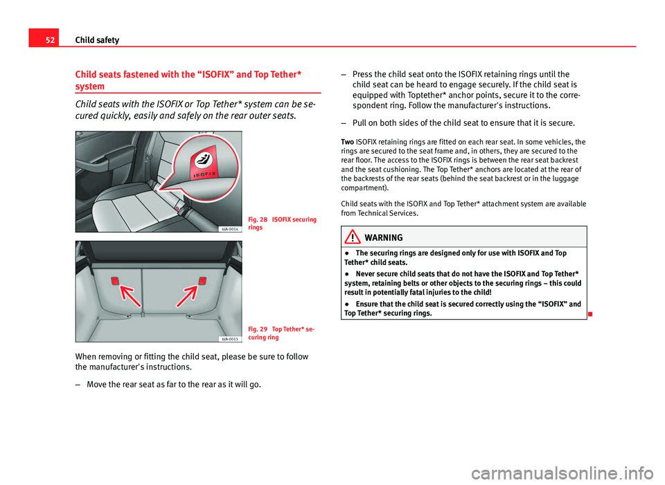
Fig. 28 ISOFIX securing
rings
Fig. 29 Top Tether* se-
curing ring
When removing or fitting the child seat, please be sure to follow
the manufacturer's instructions.
– Move the rear seat as far to the rear as it will go. –
Press the child seat onto the ISOFIX retaining rings until the
child seat can be heard to engage securely. If the child seat is
equipped with Toptether* anchor points, secure it to the corre-
spondent ring. Follow the manufacturer's instructions.
– Pull on both sides of the child seat to ensure that it is secure.
Two ISOFIX retaining rings are fitted on each rear seat. In some vehicles, the
rings are secured to the seat frame and, in others, they are secured to the
rear floor. The access to the ISOFIX rings is between the rear seat backrest
and the seat cushioning. The Top Tether* anchors are located at the rear of
the backrests of the rear seats (behind the seat backrest or in the luggage
compartment).
Child seats with the ISOFIX and Top Tether* attachment system are available
from Technical Services.
WARNING
● The securing rings are designed only for use with ISOFIX and Top
Tether* child seats.
● Never secure child seats that do not have the ISOFIX and Top Tether*
system, retaining belts or other objects to the securing rings – this could
result in potentially fatal injuries to the child!
● Ensure that the child seat is secured correctly using the “ISOFIX” and
Top Tether* securing rings.
Page 55 of 258

53
Child safety
Safety FirstOperating instructionsPractical TipsTechnical specifications
Page 56 of 258
54Controls and displays
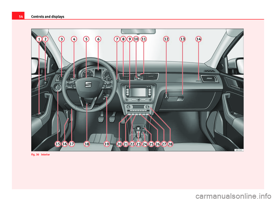
Fig. 30 Interior
Page 57 of 258
55
Controls and displays
Operating instructions Controls and displays
Overview
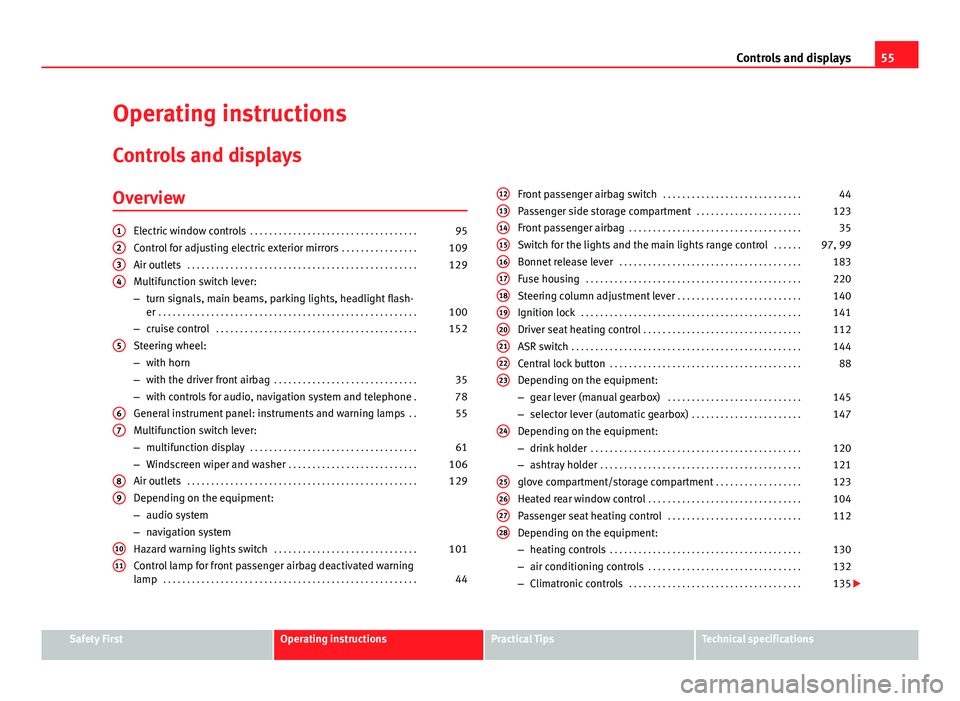
Electric window controls . . . . . . . . . . . . . . . . . . . . . . . . . . . . . . . . . . . 95
Control for adjusting electric exterior mirrors . . . . . . . . . . . . . . . .109
Air outlets . . . . . . . . . . . . . . . . . . . . . . . . . . . . . . . . . . . . . . . . . . . . . . . . 129
Multifunction switch lever:
– turn signals, main beams, parking lights, headlight flash-
er . . . . . . . . . . . . . . . . . . . . . . . . . . . . . . . . . . . . . . . . . . . . . . . . . . . . . . 100
– cruise control . . . . . . . . . . . . . . . . . . . . . . . . . . . . . . . . . . . . . . . . . . 152
Steering wheel:
– with horn
– with the driver front airbag . . . . . . . . . . . . . . . . . . . . . . . . . . . . . . 35
– with controls for audio, navigation system and telephone .78
General instrument panel: instruments and warning lamps . .55
Multifunction switch lever:
– multifunction display . . . . . . . . . . . . . . . . . . . . . . . . . . . . . . . . . . . 61
– Windscreen wiper and washer . . . . . . . . . . . . . . . . . . . . . . . . . . . 106
Air outlets . . . . . . . . . . . . . . . . . . . . . . . . . . . . . . . . . . . . . . . . . . . . . . . . 129
Depending on the equipment:
– audio system
– navigation system
Hazard warning lights switch . . . . . . . . . . . . . . . . . . . . . . . . . . . . . . 101
Control lamp for front passenger airbag deactivated warning
lamp . . . . . . . . . . . . . . . . . . . . . . . . . . . . . . . . . . . . . . . . . . . . . . . . . . . . . 44
1234
5
67
89
1011
Front passenger airbag switch
. . . . . . . . . . . . . . . . . . . . . . . . . . . . . 44
Passenger side storage compartment . . . . . . . . . . . . . . . . . . . . . .123
Front passenger airbag . . . . . . . . . . . . . . . . . . . . . . . . . . . . . . . . . . . . 35
Switch for the lights and the main lights range control . . . . . .97, 99
Bonnet release lever . . . . . . . . . . . . . . . . . . . . . . . . . . . . . . . . . . . . . . 183
Fuse housing . . . . . . . . . . . . . . . . . . . . . . . . . . . . . . . . . . . . . . . . . . . . . 220
Steering column adjustment lever . . . . . . . . . . . . . . . . . . . . . . . . . . 140
Ignition lock . . . . . . . . . . . . . . . . . . . . . . . . . . . . . . . . . . . . . . . . . . . . . . 141
Driver seat heating control . . . . . . . . . . . . . . . . . . . . . . . . . . . . . . . . . 112
ASR switch . . . . . . . . . . . . . . . . . . . . . . . . . . . . . . . . . . . . . . . . . . . . . . . . 144
Central lock button . . . . . . . . . . . . . . . . . . . . . . . . . . . . . . . . . . . . . . . . 88
Depending on the equipment:
– gear lever (manual gearbox) . . . . . . . . . . . . . . . . . . . . . . . . . . . . 145
– selector lever (automatic gearbox) . . . . . . . . . . . . . . . . . . . . . . .147
Depending on the equipment:
– drink holder . . . . . . . . . . . . . . . . . . . . . . . . . . . . . . . . . . . . . . . . . . . . 120
– ashtray holder . . . . . . . . . . . . . . . . . . . . . . . . . . . . . . . . . . . . . . . . . . 121
glove compartment/storage compartment . . . . . . . . . . . . . . . . . .123
Heated rear window control . . . . . . . . . . . . . . . . . . . . . . . . . . . . . . . . 104
Passenger seat heating control . . . . . . . . . . . . . . . . . . . . . . . . . . . . 112
Depending on the equipment:
– heating controls . . . . . . . . . . . . . . . . . . . . . . . . . . . . . . . . . . . . . . . . 130
– air conditioning controls . . . . . . . . . . . . . . . . . . . . . . . . . . . . . . . . 132
– Climatronic controls . . . . . . . . . . . . . . . . . . . . . . . . . . . . . . . . . . . . 135
121314151617181920212223
24
25262728
Safety FirstOperating instructionsPractical TipsTechnical specifications
Page 58 of 258
56Controls and displays
Note
The location of the controls of right-hand drive cars differs slightly from the
location shown here ⇒ Fig. 30. However, the symbols correspond to the re-
spective controls.
Page 59 of 258
57
Controls and displays
Instruments and warning lamps
General instrument panel – summary
Fig. 31 General instrument panel Rev counter ⇒ page 57
Digital display:
– with trip counter
⇒ page 59
– with service interval display
⇒ page 59
– with digital clock
⇒ page 60
– with multifunction display
⇒ page 61
– with informative digital display
⇒ page 66
– with outside temperature indicator
⇒ page 63
Speedometer ⇒ page 58
Coolant temperature indicator ⇒ page 58
1
2
34
Control for selecting the mode:
–
adjust hours/minutes
– activate/deactivate according to speed in mph or km/h respectively
– service intervals – show the days and kilometres (miles) remaining
Switch for:
– delete trip counter
– reset the service intervals
– adjust hours/minutes
– activate/deactivate the selected mode
Fuel reserve indicator ⇒ page 58
WARNING
● Always keep your attention on driving! As the driver, you have the full
responsibility for the safety of traffic.
● Never use the instrument panel controls when the vehicle is in mo-
tion. Do so only when the vehicle is stopped!
Rev counter
The red part of the rev counter scale 1 ⇒ Fig. 31 ⇒
page 57 marks the zone
where the engine control unit begins to limit the engine speed. The engine
control unit is responsible for reducing the revs to a safe limit.
Before the needle reaches the red zone change up into a higher gear, or
move the selector lever of the automatic gearbox to D.
In order to drive at an optimum RPM, respect the gear change indications
⇒ page 60.
5
6
7
Safety FirstOperating instructionsPractical TipsTechnical specifications
Page 60 of 258
58Controls and displays
For the sake of the environment
Changing to higher gears in advance helps to reduce fuel consumption and
noise levels, helps to protect the environment and benefits both the useful
life and the reliability of the engine.
Speedometer
Speed warning
An audible warning will be heard on exceeding 120 km/h (75 mph). If the
speed falls below this limit, the audible warning switches off.
Note
This function is only valid for certain countries.
Coolant temperature gauge
The coolant temperature gauge 4
⇒ Fig. 31
⇒ page 57 only works when
the ignition is switched on.
Damage to the engine can be avoided by observing the indications regard-
ing the temperature zones.
Engine cold
If the needle is still on the left of the scale, the engine has not yet reached
operating temperature. Avoid high engine speeds, hard acceleration and
submitting the engine to high loads.
Operating temperature zone
When the needle has reached the central part of the scale, this means the
engine has reached operating temperature. Running the engine at full throt- tle and the high temperatures involved can cause the needle to be posi-
tioned in the zone on the right.
CAUTION
The additional headlights and other parts placed in front of the fresh air in-
lets reduce the effect of engine cooling. With high outside temperatures
and engine speeds a risk becomes present of the engine overheating
⇒ page 72, Coolant level and temperature .
Fuel gauge
The fuel gauge 7 ⇒ Fig. 31 ⇒
page 57 operates only when the ignition is
switched on.
The fuel tank has a capacity of approx. 55 litres. When the needle reaches
the reserve area, the warning symbol ⇒ page 75 lights up on the gener-
al instrument panel and an audible warning can be heard.
CAUTION
Never completely empty the tank! An irregularity in the fuel supply system
can cause irregularities when the engine is running. Unburned fuel can
reach the exhaust gas system, which can cause deterioration of the catalytic
converter.
Note
Some vehicles come fitted with the fuel gauge on the general instrument
panel.