boot Seat Toledo 2014 User Guide
[x] Cancel search | Manufacturer: SEAT, Model Year: 2014, Model line: Toledo, Model: Seat Toledo 2014Pages: 200, PDF Size: 4.37 MB
Page 85 of 200

Transport and practical equipment
During an accident, even small and light ob-
jects can have so much kinetic energy that
they can cause very severe injuries. The
amount of kinetic energy depends on the
speed of the vehicle and the weight of the
object. However, the speed of the vehicle is
the most important factor.
Example: An unsecured object weighing 4.5
kg produces energy corresponding to 20
times its weight in a frontal collision at 50
km/h (31 mph). This means that its weight
reaches around 90 kg. You can imagine the
severity of the injuries that might be sus-
tained if this “projectile” strikes an occupant
as it flies through the vehicle interior. WARNING
● Store objects in the luggage compartment
and secure to the fastening points.
● In an accident or sudden manoeuvre, loose
objects in the interior can be flung forward
and possibly injure vehicle occupants or oth-
ers. This risk is even greater if the flying ob-
jects hit a triggering airbag. In this case, any
rebounding objects could injure vehicle occu-
pants. Risk of fatal injuries!
● Take into account that transporting heavy
objects changes the centre of gravity that
could also cause changes in vehicle handling.
Risk of accident! Therefore, always adjust
your speed and driving style to suit these cir-
cumstances. ●
Securing the load to the rings using unsuit-
able or damaged straps could lead to injuries
in the event of an accident or sudden braking
manoeuvre. Secure suitable straps safely to
the rings to ensure this does not happen.
● Position the load so it cannot move forward
during a sudden braking manoeuvre. Risk of
injuries!
● If transporting sharp or dangerous objects
in the space provided when the rear seats are
folded, ensure the safety of the occupant of
the remaining rear seat ››› page 8.
● If the r
ear seat located alongside a folded
seat is occupied, ensure safety, for example,
by placing the load so that it stops the seat
from folding backward in the event of being
hit from behind.
● Never drive with the rear lid open or half-
closed, exhaust gases may penetrate into the
interior of the vehicle. Danger of poisoning!
● Never exceed the allowed axle loads or al-
lowed maximum weight. Risk of accident!
● Never transport passengers in the luggage
compartment! CAUTION
Make sure sharp objects stored in the boot
cannot not damage the rear window heating
filaments. Note
Tyre pressure must be adapted to suit the
load ››› page 144, Life cycle of tyres . Category N1 vehicles
Category N1 vehicles with no protection grille
must use a retaining set compliant with
Standard EN 12195 (1 – 4) to secure the
load.
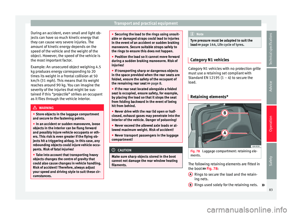
Retaining elements* Fig. 78
Luggage compartment: retaining ele-
ments. The following retaining elements are fitted in
the boot
›››
Fig. 78 :
Rin g
s to secure the load and the retain-
ing nets.
Rings used solely for the retaining nets. »
A B
83
Technical specifications
Advice
Operation
Safety
Page 86 of 200

Operation
CAUTION
The rings support a maximum load of 3.5 kN
(350 kg). Note
The front ring B is below the folding back-
rest of the rear seats ››› Fig. 78. Hook*
Fig. 79
Luggage compartment: hook. There are hooks on both sides of the boot to
secure light items of luggage such as bags,
etc.
›››
Fig. 79 . CAUTION
The side hooks support a maximum load of
7.5 kg. Retaining nets*
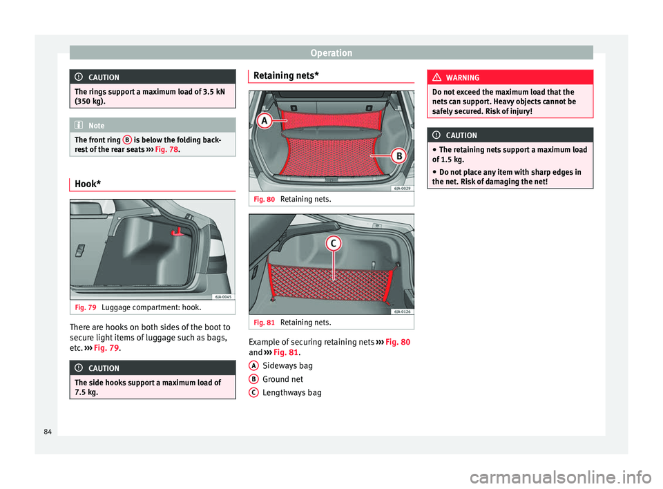
Fig. 80
Retaining nets. Fig. 81
Retaining nets. Example of securing retaining nets
››› Fig. 80
and ››› Fig. 81 .
Sidew a
ys bag
Ground net
Lengthways bag
A B
C WARNING
Do not exceed the maximum load that the
nets can support. Heavy objects cannot be
safely secured. Risk of injury! CAUTION
● The retaining nets support a maximum load
of 1.5 kg.
● Do not place any item with sharp edges in
the net. Risk of damaging the net! 84
Page 119 of 200

Towing bracket device
Description Fig. 99
Towing bracket device support for
hitching/ball-headed bar. The ball-headed bar is detachable. It is loca-
ted in the spare wheel compartment or in the
spare wheel compartment in the boot
››› page 150, Vehicle tool kit*.
Key to ››› Fig. 99
13-pin socket
Safety flange
1 2 Clamping bush
Clamping bush cap
Ball head cover
Ball-headed bar
Locking balls
Centred
Red marking on the manual regulator
Manual regulator
Key
Key slot cover
Red marking on the manual regulator
White marking on the ball-headed bar
Note
Contact an Authorised Service Partner if you
lose your key. 3
4
5
6
7
8
9
10
11
12
13
14 Placing in service position
Fig. 100
Placing in service position.
» 117Technical specifications
Advice
Operation
Safety
Page 121 of 200

Towing bracket device
Fig. 103
Placing the key slot cover. –
Remove the cap from the clamping bush 4›››
Fig. 99 by pulling downwards.
– Plac
e the ball-headed bar in the service po-
sition ››› page 117.
– Hol
d the ball-headed bar from underneath
››› Fig. 102
and push it into the clamping
bush as far as possible until you hear it
click into place ››› .
The manual regulator A
automatically turns
in the op po
site direction, adjusting to the
ball-headed bar ››› .
– Switch off the manual regulator lock with
key B by turning the key fully to the right
in the direction of arrow 1 – the arrow in
the key displays the “locked” symbol.
– Remove the key in the direction of arrow
2 .
– Place cover C over the manual regulator
lock in the direction of arrow 3
››› Fig. 103 .–
Verif
y the correct placement of the ball-
headed bar ››› page 119. WARNING
● Do not hold the manual regulator with your
hand when fitting the ball-headed bar since
you could sustain injuries to your fingers.
● When mounting the ball-headed bar, al-
ways lock it with a key and remove the key
from the slot.
● The ball-headed bar must not be in the
service position with the key in the key slot.
● If the ball-headed bar is not placed in the
service position you will not be able to place
it in the clamping bush. CAUTION
When removing the key, always place the
cover over the key slot of the manual regula-
tor to prevent dirt from entering. Note
Once removed, place the clamping bush cap
in an appropriate location in the boot. Verification of correct placement
Fig. 104
Correct placement of the ball-head-
ed bar. Before using the ball-headed bar, ensure it is
correctly fitted.
Ensure that:
● The ball-headed bar does not come out of
the clamping bush in a “jerky” manner.
● The red mark A
››› Fig. 104 on the manual
r e
gulator signals toward the white mark on
the ball-headed bar.
● The manual regulator is adjusted to the
ball-headed bar, leaving no space between
them.
● The regulator is locked and the key has
been removed.
● Cover B has been placed over the manual
regulator lock. »
119
Technical specifications
Advice
Operation
Safety
Page 122 of 200

Operation
WARNING
Only use the towing bracket device when the
ball-headed bar is properly fitted! Disassembly of the ball-headed bar
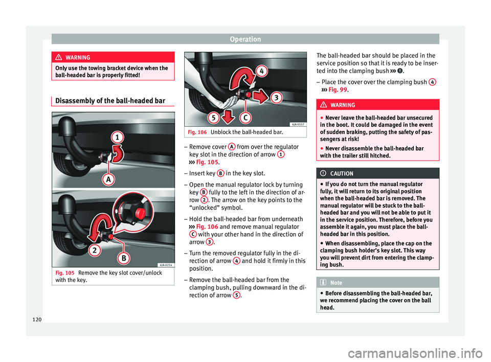
Fig. 105
Remove the key slot cover/unlock
with the key. Fig. 106
Unblock the ball-headed bar. –
Remove cover A from over the regulator
key slot in the direction of arrow 1 ›››
Fig. 105 .
– Inser
t key B in the key slot.
– Open the manual regulator lock by turning
key B fully to the left in the direction of ar-
row 2 . The arrow on the key points to the
“unlocked” symbol.
– Hold the ball-headed bar from underneath
››› Fig. 106 and remove manual regulator
C with your other hand in the direction of
arrow 3 .
– Turn the removed regulator fully in the di-
rection of arrow 4 and hold it firmly in this
position.
– Remove the ball-headed bar from the
clamping bush, pulling downward in the di-
rection of arrow 5 .The ball-headed bar should be placed in the
service position so that it is ready to be inser-
ted into the clamping bush
››› .
– Place the cover over the clamping bush 4 ›››
Fig. 99 . WARNING
● Never leave the ball-headed bar unsecured
in the boot. It could be damaged in the event
of sudden braking, putting the safety of pas-
sengers at risk!
● Never disassemble the ball-headed bar
with the trailer still hitched. CAUTION
● If you do not turn the manual regulator
fully, it will return to its original position
when the ball-headed bar is removed. The
manual regulator will be stuck to the ball-
headed bar and you will not be able to put it
in the service position. Therefore, before you
assemble it again, you must place the ball-
headed bar in this position.
● When disassembling, place the cap on the
clamping bush holder’s key slot. This way
you will prevent dirt from entering the clamp-
ing bush. Note
● Before disassembling the ball-headed bar,
we recommend placing the cover on the ball
head. 120
Page 123 of 200

Towing bracket device
●
Clean the ball-headed bar thoroughly be-
fore returning it to the on-board toolbox. Use and maintenance
Cover the clamping bush with the cap to pre-
vent dirt from entering.
Before hooking on the trailer, check the ball
head and, if necessary, lubricate it with ade-
quate lubricant.
Place the protective cover over the ball head
when storing the bar. This way, you will avoid
getting the boot dirty.
If it gets dirty, clean and dry the clamping
bush thoroughly with an appropriate prod-
uct.
CAUTION
The top part of the clamping bush opening is
lubricated. Be careful not to remove this lu-
brication. 121Technical specifications
Advice
Operation
Safety
Page 129 of 200

Care and maintenance
Underbody sealant The underside of the vehicle is coated to per-
manently protect it from chemical and me-
chanical agents.
Given that damage to the
protective coating
during driving cannot be completely ruled
out, we recommend you check the condition
of the protective coating on the underbody
and suspension at regular intervals, prefera-
bly before the start and end of the coldest
season of the year.
Authorised SEAT dealers have suitable spe-
cial products and the necessary facilities and
are aware of the techniques required for their
application. We therefore recommend all
touch-up work or additional anti-corrosion
measures be performed by an authorised
SEAT dealer. WARNING
Do not apply underseal or anti-corrosion
coatings to the exhaust pipes, catalytic con-
verter, particulate filter or heat shields on the
exhaust system. Once the engine has
reached operating temperature, these sub-
stances could catch fire. Risk of fire! Cavity waxing
All cavities on the vehicle exposed to corro-
sion are permanently factory-protected by a
wax solution
.
This wax solution does not need to be
checked or touched up. Should wax run out
of the cavities at high ambient temperatures,
remove it using a plastic scraper and clean
away any stains using lighter fluid. WARNING
Note the regulations concerning safety and
environmental protection if you use lighter
fluid to remove the wax. Risk of fire! Leatherette and upholstery
Leatherette can be cleaned with a damp
cloth. If this is not sufficient, these parts
should only be cleaned with
solvent-free
plastic care and cleaning products .
Textile covers and trim parts on doors, boot
lid, etc. can be cleaned with special deter-
gents, e.g. dry foam. A soft sponge or brush
or a micro-fibre cloth for normal cleaning can
be used. Use special products to clean the
headliner.
The dye used in many garments, for example
dark jeans, is not always sufficiently colour-
fast. Seat upholstery (fabric and leather), es- pecially when light-coloured, may visibly dis-
colour if the dye comes out of clothing, even
in normal conditions. This is not an uphols-
tery defect but indicates that the dye in the
item of clothing is not solid enough.
Heated seat upholstery Do not clean the seat upholstery with
damp
products, as this could damage the seat
he atin
g system.
Clean the upholstery with special products,
e.g. dry foam, etc.
Natural leather Leather should be looked after from time to
time, depending on its use.
Normal cleaning
Moisten a cotton or woollen cloth with water
and wipe over the leather surfaces.
More stubborn dirt
Do not let water soak through the leather or
penetrate the seams.
Dry it with a soft, dry cloth.
»
127
Technical specifications
Advice
Operation
Safety
Page 156 of 200

Advice
– Adjust the jack so that its claw surrounds
the jacking point on the door sill ››› Fig. 126
- B underneath the stamp on the door sill.
– Make sure that the base of the jack is en-
tirely supported on a flat surface and that it
is vertical ››› Fig. 126 to the point where the
c l
aw surrounds the jacking point on the
door sill.
– Continue to wind up the jack using the
crank handle until the defective wheel is
clear off the ground.
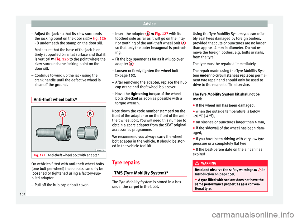
Anti-theft wheel bolts* Fig. 127
Anti-theft wheel bolt with adapter. On vehicles fitted with anti-theft wheel bolts
(one bolt per wheel) these bolts can only be
loosened or tightened using a factory-sup-
plied adapter.
– Pull off the hub cap or bolt cover. –
Insert the adapter B
››› Fig. 127 with its
t oothed s
ide as far as it will go on the inte-
rior toothing of the anti-theft wheel bolt A so that only the outer hexagonal is protrud-
ing.
– Fit the box spanner as far as it will go over
adapter B .
– Loosen or firmly tighten the wheel bolt
››› page 152 .
– Af t
er removing the adapter, replace the hub
cap or the anti-theft wheel bolt cover.
– Have the tightening torque of the wheel
bo
lts checked as soon as possible with a
tor
que wrench.
Note down the code number stamped on the
front of the adapter or on the front of the anti-
theft wheel bolt. You will need this number to
obtain a spare adapter from the SEAT original
accessories programme.
We recommend you always carry the wheel
bolt adapter in the vehicle. It should be stor-
ed in the vehicle tool kit.
Tyre repairs TMS (Tyre Mobility System)* The Tyre Mobility System is stored in a box
under the carpet in the boot.Using the Tyre Mobility System you can relia-
bly seal tyres damaged by foreign bodies,
provided that cuts or punctures are no larger
than approx. 4 mm in diameter. Do not re-
move the foreign bodies, e.g. bolts or nails,
from the tyre!
The tyre must be repaired immediately.
The repair made using the Tyre Mobility Sys-
tem
under no circumstances replaces
perm
a-
nent
tyre repair and should only be used to
drive to the nearest official service.
The Tyre Mobility System kit shall not be
used:
● If the wheel rim has been damaged,
● when the outside temperature is below
-20 °C (-4 °F),
● on slashes or punctures larger than 4 mm,
● if the sidewall of the wheel has been dam-
aged,
● If you have been driving with very low tyre
pressure or a completely flat tyre
● If the best-before date on the air can has
expired WARNING
Read and observe the safety warnings ››› in
Introduction on page 150.
● A ty r
e filled with sealant does not have the
same performance properties as a conven-
tional tyre. 154
Page 157 of 200

Emergencies
●
Do not drive faster than 80 km/h (50 mph).
● Avoid heavy acceleration, hard braking and
fast cornering.
● Check the tyre pressure after 10 minutes of
driving!
● The sealant is harmful to health and must
be immediately rinsed from affected skin. For the sake of the environment
Used or out-of-date sealant must be disposed
of in line with environmental protection regu-
lations. Note
● Observe the usage instructions provided by
the snow chain manufacturer.
● A new can of sealant can be acquired from
the selection of SEAT Original Accessories.
● Change the tyre repaired using the Tyre
Mobility System as soon as possible or ask
an official service about the possibility of re-
pairing it for you. Components of the Tyre Mobility
System*
Fig. 128
Contents of the Tyre Mobility System. The Tyre Mobility System contains the follow-
ing components:
An adapter to fit and remove the valve
Sticker indicating the speed: “max. 80
km/h” or “max. 50 mph”
Flexible filling hose with cap
Compressor
Flexible tyre inflating hose
Tyre pressure gauge
Air release screw
ON/OFF button
12 V cable connector ››› page 79
Can of sealant
1 2
3
4
5
6
7
8
9
10 Spare valve
The valve extractor 1
››› Fig. 128 has a slot
in its lo
wer end that fits onto the valve insert.
This is used to remove the valve insert from
the tyre and to replace it. This is also valid for
the spare valve insert 11 .
Work prior to using the Tyre Mobility
System The following jobs must be performed before
using the Tyre Mobility System:
– If you have a flat tyre, stop the vehicle well
away from moving traffic. Stop on flat, solid
ground.
– All vehicle occupants should leave the ve-
hicle . Vehicle occupants should wait in a
s af
e place (e.g. behind the roadside crash
barrier) while the wheel is being changed.
– Switch off the ignition and engage neutral
or move the selector lever on the automatic
g
earbox to position P.
– Apply the handbrake firmly.
– Check
whether the tyre can be repaired us-
ing the Tyre Mobility System ›››
page 154.
– If towing a trailer, unhitch it.
– Remove the Tyre Mobility System from the
boot
. »
11
155
Technical specifications
Advice
Operation
Safety
Page 173 of 200

Fuses and bulbs
Position of the bulbs››› Fig. 156Bulb function
ATurn signals: PY21W NA LL
BSide lights-brake lights: P21/5W
CSide lights: P21/5W Note
Check the condition of the seal. If damaged, a
replacement can be acquired from an Official
Service. Fitting rear light
Fig. 157
Fit the tail light unit. Fig. 158
Fit the tail light unit. –
Make sure the connector is correctly in
place.
– Press the rear light unit backwards (driving
direction) by fitting the fastenings into the
rubber mountings ››› Fig. 157 A .
– Take the screwdriver or a Torx 20 key (T20)
from the vehicle tool kit and tighten (turn-
ing clockwise ››› Fig. 158 ) the two retaining
s c
rews that secure the front of the light. Changing rear lights (in rear
lid)
Remove the bulb holder Fig. 159
Remove the cover from the boot lid.
» 171
Technical specifications
Advice
Operation
Safety