change wheel Seat Toledo 2014 Owner's manual
[x] Cancel search | Manufacturer: SEAT, Model Year: 2014, Model line: Toledo, Model: Seat Toledo 2014Pages: 200, PDF Size: 4.37 MB
Page 42 of 200

Operation
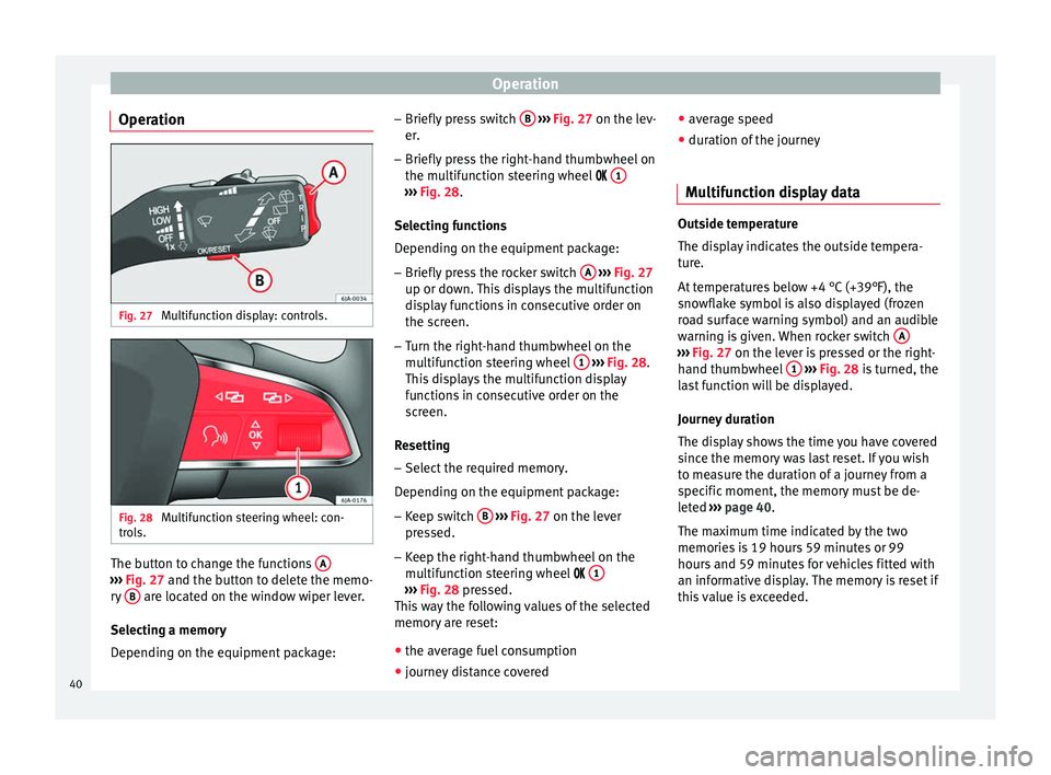
Operation Fig. 27
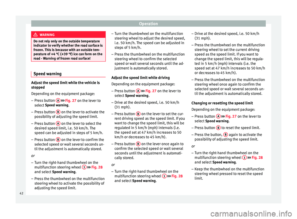
Multifunction display: controls. Fig. 28
Multifunction steering wheel: con-
trols. The button to change the functions
A›››
Fig. 27 and the button to delete the memo-
r y
B are located on the window wiper lever.
Selecting a memory
Depending on the equipment package: –
Briefly press switch B
››› Fig. 27 on the lev-
er .
– Briefly
press the right-hand thumbwheel on
the multifunction steering wheel 1 ›››
Fig. 28 .
Sel ectin
g functions
Depending on the equipment package:
– Briefly press the rocker switch A
››› Fig. 27
up or down. This displays the multifunction
display functions in consecutive order on
the screen.
– Turn the right-hand thumbwheel on the
multifunction steering wheel 1
››› Fig. 28.
This displays the multifunction display
functions in consecutive order on the
screen.
Resetting
– Select the required memory.
Depending on the equipment package: – Keep switch B
››› Fig. 27 on the lever
pr e
ssed.
– Keep the right-hand thumbwheel on the
multifunction steering wheel 1 ›››
Fig. 28 pressed.
Thi s
way the following values of the selected
memory are reset:
● the average fuel consumption
● journey distance covered ●
average speed
● duration of the journey
Multifunction display data Outside temperature
The display indicates the outside tempera-
ture.
At temperatures below +4 °C (+39°F), the
snowflake symbol is also displayed (frozen
road surface warning symbol) and an audible
warning is given. When rocker switch
A ›››
Fig. 27 on the lever is pressed or the right-
h and thumb
wheel 1
›››
Fig. 28 is turned, the
l a
st function will be displayed.
Journey duration
The display shows the time you have covered
since the memory was last reset. If you wish
to measure the duration of a journey from a
specific moment, the memory must be de-
leted ›››
page 40
.
The maximum time indicated by the two
memories is 19 hours 59 minutes or 99
hours and 59 minutes for vehicles fitted with
an informative display. The memory is reset if
this value is exceeded.
40
Page 44 of 200

Operation
WARNING
Do not rely only on the outside temperature
indicator to verify whether the road surface is
frozen. This is because with an outside tem-
perature of +4 °C (+39 °F) ice can form on the
road - Warning of frozen road surface! Speed warning
Adjust the speed limit while the vehicle is
stopped
Depending on the equipment package:
– Press button A
›››
Fig. 27 on the lever to
select Speed warning
.
– Press button B on the lever to activate the
possibility of adjusting the speed limit.
– Press button A on the lever to select the
desired speed limit, i.e. 50 km/h. The
speed can be adjusted in steps of 5 km/h.
– Press button B on the lever to confirm the
selected speed or wait several seconds un-
til the adjustment is automatically stored.
or – Turn the right-hand thumbwheel on the
multifunction steering wheel 1
›››
Fig. 28
and select Speed warning
.
– Press the thumbwheel on the multifunction
steering wheel to activate the possibility of
adjusting the speed limit. –
Turn the thumbwheel on the multifunction
steering wheel to adjust the desired speed,
i.e. 50 km/h. The speed can be adjusted in
steps of 5 km/h.
– Press the thumbwheel on the multifunction
steering wheel to confirm the selected
speed or wait several seconds until the ad-
justment is automatically stored.
Adjust the speed limit while driving
Depending on the equipment package: – Press button A
››› Fig. 27 on the lever to
select Speed warning.
– Drive at the desired speed, i.e. 50 km/h
(31 mph).
– Press button B on the lever to set the cur-
rent driving speed as the speed limit. If you
want to change the speed limit, this will be
regulated in 5 km/h (mph) intervals (i.e.
the speed set at 47 km/h increases to 50
km/h or decreases to 45 km/h).
– Press button B on the lever once again to
confirm the selected speed or wait several
seconds until the adjustment is automati-
cally stored.
or – Turn the right-hand thumbwheel on the
multifunction steering wheel 1
››› Fig. 28
and select Speed warning. –
Drive at the desired speed, i.e. 50 km/h
(31 mph).
– Press the thumbwheel on the multifunction
steering wheel to set the current driving
speed as the speed limit. If you want to
change the speed limit, this will be regula-
ted in 5 km/h (mph) intervals (i.e. the
speed set at 47 km/h increases to 50 km/h
or decreases to 45 km/h).
– Press the thumbwheel on the multifunction
steering wheel once again to confirm the
selected speed or wait several seconds un-
til the adjustment is automatically stored.
Changing or resetting the speed limit
Depending on the equipment package: – Press button A
››› Fig. 27 on the lever to
select Speed warning.
– Press button B to reset the speed limit.
– Press the button, B again to activate the
possibility of adjusting the speed limit.
or – Turn the right-hand thumbwheel on the
multifunction steering wheel 1
››› Fig. 28
and select Speed warning.
– Keep the thumbwheel on the multifunction
steering wheel pressed to reset the speed
limit.
42
Page 48 of 200

Operation
Resetting service interval display
The service interval display can be reset only
after a service message or pre-warning has
been displayed in the general instrument
panel display.
To reset the display, it is advisable to visit a
technical service, to perform the following ac-
tions:
● reset the display memory after performing
the applicable inspection,
● record the information in the Maintenance
Programme,
● place a sticker on the side of the instru-
ment panel in the driver area indicating the
date of the next inspection.
The service interval display can be reset by
pressing the 6
››› Fig. 24
›
›› page 30 button.
In vehicles equipped with an informative dis-
play the service interval display can be reset
from the menu, Settings ››› page 44. CAUTION
We advise against resetting the service inter-
val display yourself, given that this action
could upset service intervals, and as a result,
lead to faults in the vehicle. Note
● Never reset the display between service in-
tervals as this could lead to erroneous indica-
tions.
● After disconnecting the battery of the vehi-
cle, the service interval display values remain
stored.
● If the general instrument panel is changed
after a repair, the correct values must be in-
put in the service interval display. This opera-
tion is carried out by a specialised service.
● After resetting the display with flexible
service intervals, the information will be indi-
cated in the same way as vehicles with fixed
service intervals. Therefore, we recommend
that a SEAT Authorised Service resets the
service interval display, who will do so cor-
rectly using diagnostics equipment.
● For more detailed information, please con-
sult the Maintenance Programme. Communication
Steering wheel controls* General information The vehicle includes a multifunction module
from where it is possible to control the audio,
telephone and radio/navigation functions
without needing to distract the driver.
There are two versions of the multifunction
module:
●
Audio version, to control the available au-
dio functions from the steering wheel (Radio,
audio CD, MP3 CD, iPod ®1)
, USB 1)
).
● Audio + telephone versions o control the
available audio functions from the steering
wheel (Radio, audio CD, MP3 CD, iPod ®1)
,
USB 1)
, SD 1)
) and the Bluetooth system. 1)
Depending on the vehicle equipment.
46
Page 49 of 200

Communication
Audio system operation Fig. 31
Controls on the steering wheel.ButtonRadioMedia (except AUX)AUX
A TurnUp/down volumeUp/down volumeUp/down volume
A PressNo functionNo functionNo function
BMutePauseMute
CSearch for last stationShort press: switch to the previous song
Hold down: quick rewindNo function
DSearch for the next stationShort press: switch to the next song
Hold down: fast forwardNo function
EPrevious presetPrevious folderNo function
FNext preset stationNext folderNo function
GChange sourceChange sourceChange source
H TurnSwitch MFA functionSwitch MFA functionSwitch MFA function
H PressActs on the MFAActs on the MFAActs on the MFA 47
Technical specifications
Advice
Operation
Safety
Page 50 of 200

Operation
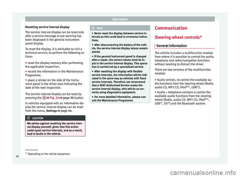
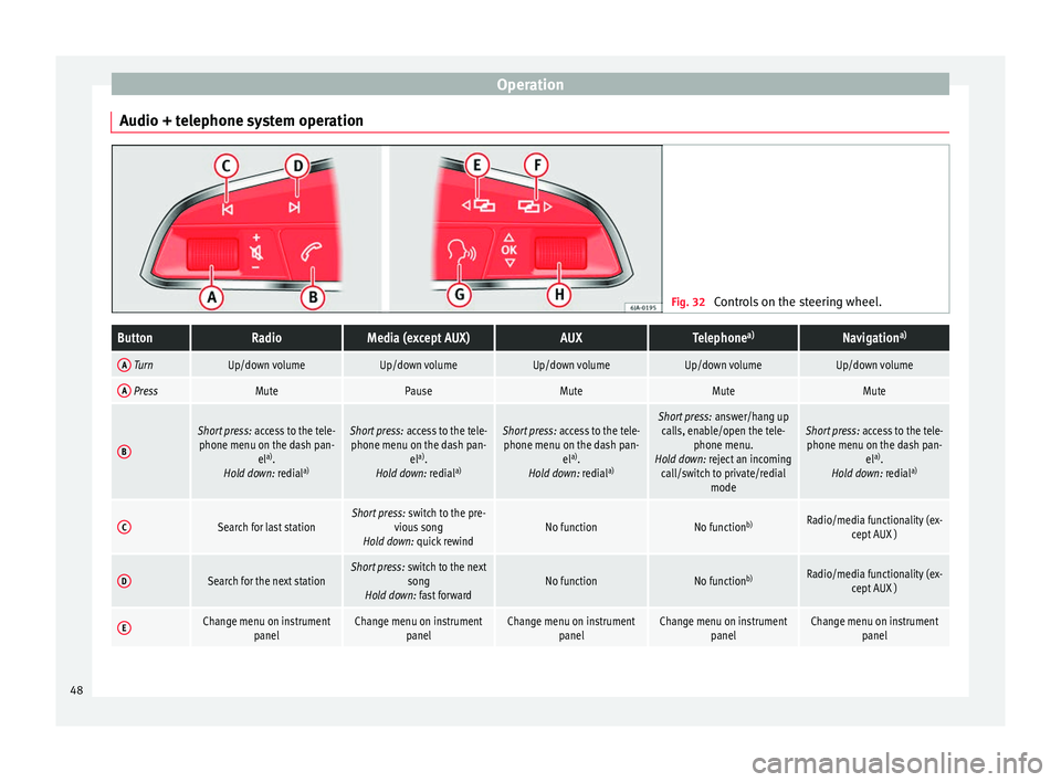
Audio + telephone system operation Fig. 32
Controls on the steering wheel.ButtonRadioMedia (except AUX)AUXTelephone a)Navigation a)
A TurnUp/down volumeUp/down volumeUp/down volumeUp/down volumeUp/down volume
A PressMutePauseMuteMuteMute
B
Short press:
access to the tele-
phone menu on the dash pan- ela)
.
Hold down: redial a)Short press:
access to the tele-
phone menu on the dash pan- ela)
.
Hold down: redial a)Short press:
access to the tele-
phone menu on the dash pan- ela)
.
Hold down: redial a)Short press:
answer/hang up
calls, enable/open the tele- phone menu.
Hold down: reject an incoming call/switch to private/redial modeShort press: access to the tele-
phone menu on the dash pan- ela)
.
Hold down: redial a)
CSearch for last stationShort press:
switch to the pre-
vious song
Hold down: quick rewindNo functionNo function b)Radio/media functionality (ex-
cept AUX )
DSearch for the next stationShort press: switch to the next
song
Hold down: fast forwardNo functionNo function b)Radio/media functionality (ex-
cept AUX )
EChange menu on instrument panelChange menu on instrumentpanelChange menu on instrumentpanelChange menu on instrumentpanelChange menu on instrumentpanel48
Page 51 of 200

CommunicationButtonRadioMedia (except AUX)AUXTelephone
a)Navigation a)
FChange menu on instrument
panelChange menu on instrumentpanelChange menu on instrumentpanelChange menu on instrumentpanelChange menu on instrumentpanel
GEnable/disable voice control a)Enable/disable voice controla)Enable/disable voice controla)No functionb)Enable/disable voice control
H TurnNext/previous preset station c)Next/previous songc)Acts upon the dash panel
menu depending on where it is locatedActs upon the dash panel
menu depending on where it is locatedActs upon the dash panel
menu depending on where it is located
H Press
Acts on the MFA or confirms
the menu option of the dash
panel depending on the menu optionActs on the MFA or confirms
the menu option of the dash
panel depending on the menu optionActs on the MFA or confirms
the menu option of the dash
panel depending on the menu optionActs on the MFA or confirms
the menu option of the dash
panel depending on the menu optionActs on the MFA or confirms
the menu option of the dash
panel depending on the menu option
a)According to the vehicle's equipment package.
b) When a call is being made, radio/media functionality (except AUX).
c) Only if the dash panel is in audio menu.
Voice control Fig. 33
Multifunction steering wheel: voice
control. The time during which the system is ready to
receive voice commands and execute them is
called dialogue. The system provides acous-
tic warnings and if necessary, will guide you
through the respective functions.
It is recommended to use the
Help menu the
first time that voice control is used in order to
familiarize yourself with this function.
Optimum operation of the voice commands
depends on several factors:
● Speak slowly and clearly, as far as possi-
ble. The system will not recognise words pro-
nounced unclearly, or words and numbers in
which syllables are omitted. ●
Speak with normal voice volume, without
exaggerated intonation or long pauses.
● Close the doors, windows and sunroof for
the purpose of dampening or insulating
against unwanted noise from the exterior. Do
not aim the air from the diffusers at the roof.
● If you are driving very fast, it is recommen-
ded that you speak a little louder.
● While talking, avoid making other noise in-
side the vehicle, i.e., occupants that are talk-
ing at the same time.
● Do not speak when the system is providing
information. »
49
Technical specifications
Advice
Operation
Safety
Page 65 of 200

Lights and visibility
Turn signal and main beam lever Fig. 47
Turn signal and main beam lever. The turn signal and main beam lever also op-
erates the parking lights and the headlight
flasher.
Right and left-hand
turn signal
– Move the lever ››› Fig. 47 up A or down
B .
– In order for the turn signals to flash three
times (turn signal to change lanes), move
the lever briefly up or down just as far as
point of resistance and then release it.
– Keep the lever held down at the point of re-
sistance for the turn signals to flash for as
long as you hold the lever, e.g. when
changing lanes.
Main beams
– Switch on the dipped beam ›››
page 61. –
Press the lever ››› Fig. 47 forward in the di-
r ection indic
ated by arrow C .
– Pull the lever back to its original position in
the direction indicated by arrow D to
switch the main beam off.
Headlight flasher
– Pull the lever ››› Fig. 47 towards the steer-
ing wheel (point of resistance) in the direc- tion indicated by arrow D .
Parking lights
Instructions for use ››› page 65. CAUTION
Never use the main beam headlights or the
headlight flasher if they could dazzle other
drivers. Note
● The turn signals only work when the igni-
tion is switched on. The corresponding warn-
ing lamp or flashes in the general instru-
ment p
anel.
● The turn signals switch off automatically
when the steering wheel is returned to the
straight-ahead position.
● If a turn signal bulb is defective, the control
lamp flashes at double speed. Automatic headlight control (AHC)
If the light switch is in this position
››› Fig. 45, the side lights, headlights and the
number p l
ate lights will turn on or off auto-
matically.
The light is adjusted according to the data re-
corded by the light sensor that is installed
between the windscreen and the inside rear
view mirror.
If the light switch is in position , the sym-
bol located next to the light switch will il-
luminate. If the light illuminates automatical-
ly, symbol located next to the light switch
will also illuminate.
Automatic headlights in case of rain
If the light switch is in position and is
connected to the automatic wipe in case of
rain for more than 10 seconds or wipe (posi-
tion 2 or
3 ) for longer than 15 seconds,
››› page 69 then the side lights and head-
lights w
ill automatically switch on.
The light automatically switches off if more
than 4 minutes have elapsed and the auto-
matic wipe or wipe (position 2 or
3 ) have
not been switched on. »
63
Technical specifications
Advice
Operation
Safety
Page 71 of 200

Lights and visibility
●
Remove snow and ice from the wipers be-
fore starting your journey.
● Careless handling could lead to the wiper
arms damaging the windscreen.
● For safety reasons, the wiper blades should
be changed once or twice a year. They can be
purchased at a SEAT Authorised Service.
● The ignition cannot be switched on while
the windscreen wiper arms are in a raised po-
sition. Otherwise, the windscreen wipers
would return to their original position and
could damage the paintwork on the bonnet. Note
Keep the wipers clean. The wipers can be
soiled with remains of wax solutions from car
washes ››› page 124.
● On vehicles equipped with windscreen
washer jets, these are heated once the en-
gine is running. Handling windscreen wipers and
washers
Fig. 56
Window wiper lever. Short wipe
– Give the windscreen a brief wipe by moving
the lever down to position 4
››› Fig. 56 .
W ipe int
ervals/automatic wipe with rain
sensor*
– Push the lever up to position 1
››› Fig. 56 .
– With sw
itch A , adjust the wipe interval or
rain sensor sensitivity.
Switch A has 4 positions.
The rain sensor* is part of the intermittent
wipe function.
The rain sensor* controls the frequency of
the windscreen wiper intervals, depending
on the amount of rain. Slow wipe
–
Push the lever up to position 2
››› Fig. 56 .
C ontinuou
s wipe
– Push the lever up to position 3
››› Fig. 56 .
Aut om
atic windscreen wash and wipe
– Pull the lever towards the steering wheel,
position 5
››› Fig. 56 , and the windscreen
w a
sher and wipers are switched on.
– Release the lever. The washer will stop and
the windscreen wipers will keep running for
1-3 wipes (depending on the windscreen
washer operating time).
Rear window wiper*
– Press the lever forward to position 6 ›››
Fig. 56 and the rear window wiper will
ru n ev
ery 6 seconds.
Automatic rear window wash and wipe* – Press the lever fully forward to position 7 ›››
Fig. 56 and the rear window wiper and
w a
sher switch on at the same time.
– Release the lever. The rear window washer
will stop and the rear window wipers will
keep running for 1-3 wipes (depending on
the jet operating time). When released, the
lever remains in position 6 .
»
69
Technical specifications
Advice
Operation
Safety
Page 73 of 200

Seats and head restraints
●
Do not touch the exterior mirrors when the
heating system is running.
● If the electrical adjustment should ever fail
to operate, the rear vision mirrors can be ad-
justed by hand by pressing the edge of the
mirror glass.
● Visit the technical service in the event of a
fault in the electrical rear vision mirror ad-
justment system. Seats and head restraints
Adjusting seats and head
restraints
Introduction Set the driver seat in such a way that the
pedals can be fully depressed with your legs
slightly bent.
Set the driver seat backrest so that you can
reach the upper point of the steering wheel
with your arms slightly bent.
The correct seat position is very important
for:
●
reaching all of the controls safely and
quickly,
● a relaxed posture that will not produce fati-
gue,
● maximum protection from the seat belts
and airbag system WARNING
● Adjust the driver seat only when the vehi-
cle is stationary. Risk of accident!
● Be careful when adjusting the front seats!
Careless and uncontrolled adjustment can
cause injuries. ●
The backrests must not be reclined too far
back while driving. This could limit the effect
of the seat belts and the airbag system. Risk
of injury!
● Never transport more than the permitted
amount of people in your vehicle.
● Every occupant in the vehicle must properly
fasten and wear the seat belt belonging to
his or her seat. Children must be protected
with an appropriate child restraint system
››› page 24, Transporting children safety.
● The front seats, head restraints and seat
belts must always be adjusted to the size of
the vehicle occupant to provide you and your
passengers with the greatest possible protec-
tion.
● Your feet should remain in the footwell
while the vehicle is moving; never rest them
on the dash panel, on the window or on the
seat! This also applies to passengers. An in-
correct sitting position exposes you to an in-
creased risk of injury in case of a sudden
braking or an accident. If the airbag is trig-
gered, you could sustain severe injuries due
to an incorrect sitting position!
● It is important for the driver and front pas-
senger to keep a distance of at least 25 cm
from the steering wheel and dash panel. Fail-
ure to respect the minimum distance means
that the airbag will not protect you. Risk of
fatal injury if triggered!
● Objects must not be placed in the footwell,
as they could move to the area of the pedals
in the event of a braking manoeuvre or
change of direction. This would prevent the » 71Technical specifications
Advice
Operation
Safety
Page 101 of 200

Driving
●
On long, steep gradients, reduce your
speed and change to a lower gear (manual
gearbox) or move the selector lever to a lower
gear position (automatic gearbox). This uses
the force of the engine and the brakes do not
suffer as much. If you still have to brake, do
so intermittently, pressing down repeatedly
on the brake pedal.
● Vehicle modifications (e.g. to the engine,
brakes, frame or a combination of wheels and
tyres) could impair the brake assist systems
››› page 122, Accessories and modifications
to the vehicle .
● In the event of a fault in the ABS system,
the ESC, TCS and EDL are switched off auto-
matically. A fault in the ABS is indicated by
the ››› page 36 warning lamp. Brakes
Wear
The rate of wear of the brake pads depends
on the driving style and on the way in which
the vehicle is used. The brake pads will wear
more quickly if you use your vehicle frequent-
ly in urban traffic and short trips or drive in a
sporty style. Under these
demanding condi-
tions , visit your specialised service, even be-
f or
e the scheduled service date, so that the
thickness of the brake pads can be meas-
ured. Wet roads or road salt
If brakes are wet or frozen, or if you are driv-
ing on roads which have been gritted with
salt, braking power may set in later than nor-
mal. Dry the brakes as soon as possible by
braking repeatedly.
Corrosion
Long periods of inactivity and little use can
lead to rust on the brake discs and dirt on the
brake pads. Where the brake system is sub-
jected to light stress or in the case of corro-
sion, clean the brake discs by braking fully
several times at a high speed.
Brake system fault
If you notice that the braking distance sud-
denly increases and the brake pedal can be
pressed down more fully, there may be a fault
in the brake system. Visit a specialised serv-
ice immediately and adjust your driving style
to the extent of the damage and to limit the
effect of the brakes.
Low brake fluid level
Insufficient brake fluid could cause faults in
the brake system. The brake fluid level is con-
trolled electronically
››› page 33, Brake sys-
tem . Brake servo
The brake servo supplements the pressure
you exert on the brake pedal. The brake servo
only works when the engine is running.
Handbrake Fig. 90
Centre console: handbrake. Applying the handbrake
– Pull the handbrake lever up all the way.
Releasing the handbrake
– Pull the handbrake lever up slightly and
press the unlock button at the same time
››› Fig. 90 .
– Keep the b
utton pressed down and push
the lever all the way down.
The warning lamp lights up when the hand-
brake is applied with the ignition on .
99
Technical specifications
Advice
Operation
Safety