service indicator Seat Toledo 2014 Owner's manual
[x] Cancel search | Manufacturer: SEAT, Model Year: 2014, Model line: Toledo, Model: Seat Toledo 2014Pages: 200, PDF Size: 4.37 MB
Page 32 of 200

Operation
Instruments and warning lamps
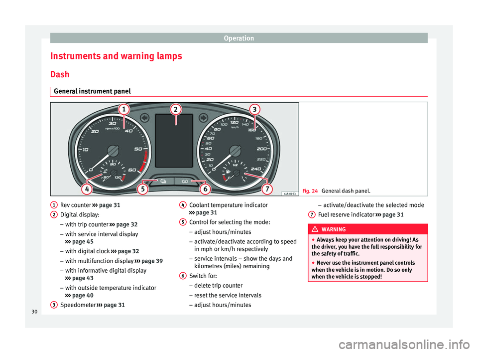
Dash General instrument panel Fig. 24
General dash panel. Rev counter
››› page 31
Digital display:
– with trip counter ››› page 32
– with service interval display
››› page 45
– with digital clock ››› page 32
– with multifunction display ››› page 39
– with informative digital display
››› page 43
– with outside temperature indicator
››› page 40
Speedometer ››› page 31
1 2
3 Coolant temperature indicator
››› page 31
Control for selecting the mode:
– adjust hours/minutes
– activate/deactivate according to speed
in mph or km/h respectively
– service intervals – show the days and
kilometres (miles) remaining
Switch for:
– delete trip counter
– reset the service intervals
– adjust hours/minutes
4 5
6 –
activate/deactivate the selected mode
Fuel reserve indicator ››› page 31 WARNING
● Always keep your attention on driving! As
the driver, you have the full responsibility for
the safety of traffic.
● Never use the instrument panel controls
when the vehicle is in motion. Do so only
when the vehicle is stopped! 7
30
Page 34 of 200

Operation
Trip counter* Daily trip counter (trip)
The daily trip counter indicates the distance
that has been covered since the last time the
function was reset in 100 metre sections.
In order to reset the daily distance covered
keep the button
6
››› Fig. 24 ››› page 30
pressed down.
Odometer
The odometer indicates the total number of
kilometres (or mileage) that the vehicle has
covered until now.
Fault indication
In the event of a fault the word Error
will be
permanently displayed on the informative
display. Please take the vehicle to a special-
ised Technical Service to solve this fault. Note
In vehicles equipped with an informative dis-
play, if the indicator of the second speed in
mph or in kph are activated respectively, this
speed will be displayed in place of the odom-
eter. Digital clock
The clock is set using the buttons
5 to
6 ›››
Fig. 24 ››› p
age 30.
Select the indication you want to change with
button 5 and make the adjustment with but-
ton 6 .
In vehicles equipped with an informative dis-
play this can be reset from the menu, Time
››› page 44.
R ec
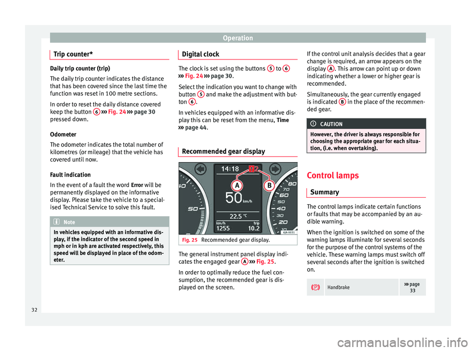
ommended gear display Fig. 25
Recommended gear display. The general instrument panel display indi-
cates the engaged gear
A
›››
Fig. 25 .
In or der t
o optimally reduce the fuel con-
sumption, the recommended gear is dis-
played on the screen. If the control unit analysis decides that a gear
change is required, an arrow appears on the
display
A . This arrow can point up or down
indicating whether a lower or higher gear is
recommended.
Simultaneously, the gear currently engaged
is indicated B in the place of the recommen-
ded gear. CAUTION
However, the driver is always responsible for
choosing the appropriate gear for each situa-
tion, (i.e. when overtaking). Control lamps
Summary The control lamps indicate certain functions
or faults that may be accompanied by an au-
dible warning.
When the ignition is switched on some of the
warning lamps illuminate for several seconds
for the purpose of the control systems of the
vehicle. These warning lamps must switch off
several seconds after the ignition is switched
on.
Handbrake›››
page
33 32
Page 46 of 200

Operation
Settings You can make certain adjustments using the
informative display. The current values are
displayed directly in their respective places
above and below the line.
The following items can be selected:
■ Language
■ MFD data
■ Time
■ Winter tyres
■ Units
■ Second speed
■ Inspec. Service
■ Factory settings
■ Back
Select the option Back
to return to the superi-
or menu level.
Language
Here the language used to display the warn-
ing and information texts can be selected.
MFD data
Here certain data shown on the multifunction
display can be switched on or off. Time
In this menu you can set, the time, the dis-
play format (24 or 12 hours) and changes
from winter to summer time.
Winter tyres
The speed at which an audible warning is
given can be adjusted here. This function can
be used with winter tyres, whose maximum
permitted speed is lower than the maximum
speed of the vehicle.
When exceeding the maximum speed the fol-
lowing is shown on the display:
Winter tyres max speed … km/h … (mph)
Units
The units of measure for temperature, con-
sumption and journey distances can be set
here.
Second speed
The second speed can be activated/deactiva-
ted in mph or km/h respectively here.
Inspection Service
Here you can choose to display the kilome-
tres (miles) and days remaining until the next
service, and reset the service interval display. Factory settings
Select
Factory setting to reset the values of
the informative display to their factory set-
tings.
Door, rear lid or bonnet open indicator If at least one of the doors, rear lid or bonnet
is open, a symbol is shown on the informa-
tive display indicating that the door, rear lid
or bonnet concerned is
open.
An audib l
e warning is also given simultane-
ously if the vehicle is being driven at a speed
higher than 6 km/h (4 mph).
Auto-check system Vehicle status
When the ignition is switched on, some vehi-
cle functions such as the condition of its sys-
tems are continually checked.
The warning messages about eventual faults
in addition to other information is displayed
on the informative display. This information
is displayed together with the respective
symbols on the informative display or by
warning lamps that illuminate on the general
instrument panel
›››
page 32 .
The option, V
ehic
le status , appears in the
menu when at least one warning message is
44
Page 139 of 200

Checking and refilling levels
climbing on mountain passes, the oil level
should preferably be kept within area A ,
but
no higher .
A w
arning lamp will appear on the instrument
panel ››› page 34, Engine oil if the oil lev-
el is too low. In this case, check the oil level
as soon as possible. Top up with the required
amount of oil. CAUTION
● The oil level must never exceed area A›››
Fig. 111. Risk of damage to the exhaust
sy s
tem!
● If the engine oil cannot be topped up under
the given conditions, do not drive on! Stop the engine and seek
the professional assis-
tance of an Official Service, as this could
cause serious damage to the engine. Topping up engine oil
–
Check the engine oil level ›››
page 136,
Checking the engine oil level .
– Unscrew the cap from the filler opening.
– Put in the specified grade of oil 0.5 litres at
a time ›››
page 135 .
– Chec k
the oil level ›››
page 136.
– Replace the oil filler cap carefully and push
the dipstick all the way in. Changing engine oil Engine oil must be changed with the frequen-
cy indicated in the Maintenance Programme
or according to the service interval indicator
››› page 45. CAUTION
Do not mix engine oil with additives. Risk of
damage to the engine! Damage caused by
these products is not covered by the warran-
ty. Note
Wash your skin thoroughly if it comes into
contact with engine oil. Coolant
General notes The cooling system is factory-filled with an
anti-freeze product.
Coolant consists of a mixture of water and
40% anti-freeze additive. This mixture gives
the required anti-freeze protection at temper-
atures down to -25 °C (-13 °F) and protects
the cooling and heating system against cor-
rosion. It also prevents scaling and raises the
boiling point of the coolant considerably.The coolant concentration must not be re-
duced by adding water, even in warmer sea-
sons or in warm countries.
The concentration
of the anti-freeze additive in the coolant
must be at least 40 %.
If greater anti-freeze protection is required in
very cold climates, the proportion of the anti-
freeze additive can be increased, but only up
to 60% (anti-freeze protection down to ap-
proximately -40 °C (-40 °F)). Exceeding this
proportion reduces anti-freeze protection and
the cooling effect.
Coolant fluid with protection down to -35 °C
(-31 °F) is added at the factory in vehicles
destined for countries with a cold climate. In
these countries, the concentration of coolant
should always be kept above 50%.
The type of anti-freeze to be used for topping
up is indicated on the coolant tank cover
››› Fig. 112 . CAUTION
● Anti-freeze that does not correspond to the
correct specification may particularly affect
corrosion protection considerably.
● Faults caused by corrosion may lead to
coolant leaks. Risk of serious engine faults! 137
Technical specifications
Advice
Operation
Safety
Page 144 of 200

Advice
Checking battery acid level Fig. 116
Battery: Electrolyte level indicator. We recommend you have the acid level regu-
larly checked at an official technical service,
particularly in the following cases.
● At high outside temperatures.
● On long daily trips.
● Whenever the vehicle is loaded
››› page 142, Charging the battery .
In v
ehicles equipped with a battery with col-
our indicator, the so-called magic eye
››› Fig. 116
changes colour to indicate the
acid level.
Air bubbles can influence the colour of the in-
dicator. Therefore, carefully knock the indica-
tor before checking the acid level.
● Black – the acid level is correct.
● Colourless or light yellow – acid level too
low, battery must be changed. Note
● The battery acid level is also regularly
checked during servicing at authorised SEAT
dealers.
● The electrolyte level on “AGM” batteries
cannot be checked for technical reasons.
● Vehicles equipped with the “Start-Stop”
system include a battery control unit to con-
trol the battery level for repeated engine
starting. Winter service
At low temperatures the battery provides only
a fraction of the starting power it has at nor-
mal temperatures.
A flat battery can also freeze at temperatures
slightly below to 0 °C (32 °F).
We therefore recommend you have the bat-
tery checked and, if necessary, charged at an
official SEAT technical service before the start
of winter.
Charging the battery A fully-charged battery is essential for relia-
ble starting.
– Switch off the ignition and all electrical
equipment. –
For “fast-charging” only: disconnect both
battery connection cables (first the “nega-
tive” terminal and then the “positive”).
– Connect the charger cables to the battery
terminals (red = “positive”, black = “nega-
tive”).
– Plug in the battery charger and switch on.
– After charging the battery: Switch off the
battery charger and disconnect the cable.
– Remove the charger cables.
– If necessary, reconnect both battery cables
to the battery (first the “positive” cable,
then the “negative” cable).
When charging with a low current (e.g. with a
small battery charger ), the battery does not
normally have to be disconnected. The in-
structions of the battery charger manufactur-
er must be followed.
Use a current equivalent to or lower than
10% of the battery capacity to fully charge
the battery.
Before “ fast-charging
” the battery however,
both b
attery cables must be disconnected.
“Fast-charging” a battery is dangerous and
requires a battery charger and special knowl-
edge. Fast charges should be performed by
an official technical service.
The battery caps should not be opened while
the battery is being charged.
142
Page 147 of 200

Wheels and tyres
indicators is given on the tyre sidewalls by
the letters “TWI”, triangular symbols or other
symbols.
The useful life of the tyres depends primarily
on the following factors:
Tyre pressure values
Under-inflation or over-inflation will consider-
ably reduce the useful life of the tyres and
impair the vehicle's handling. Therefore,
check the tyre pressure, including the spare
wheel, at least once a month and before any
long journey.
Inflation pressures for summer tyres are lis-
ted on a sticker inside the fuel tank flap. The
pressures for winter tyres are 0.2 bar (2.9
psi/20 kPa) above the summer values.
Always check the pressure when the tyre is
cold. Do not reduce over-pressure in warm
tyres. The tyre pressures must be altered to
suit notable changes in the load being car-
ried.
Driving style
Fast cornering, heavy acceleration and hard
braking all increase tyre wear.
Wheel balancing
The wheels on new vehicles are balanced.
Various factors encountered when driving
can cause them to become unbalanced, which results in vibration of the steering
wheel.
The wheel must be rebalanced if a new tyre is
fitted or if a tyre is repaired.
Incorrect wheel alignment
Incorrect front or rear wheel alignment cau-
ses excessive tyre wear, frequently on one
side, and also impairs vehicle safety. If tyre
wear is very irregular, contact an Official
Service.
Tyre damage
To avoid damage to tyres and wheels, only
drive over kerbs or similar obstacles slowly
and at a right angle if possible.
Check tyres and wheels regularly for damage
(punctures, cracks, blisters, deformities,
etc.). Remove any foreign objects embedded
in outside of the treads.
Unusual vibration or the car pulling to one
side may indicate that one of the tyres is
damaged.
Reduce speed immediately and
s t
op if you suspect that damage may have
occurred! Check the tyres for damage (blis-
ter
s, cracks, etc.). If no external damage is
visible, drive slowly and carefully to the near-
est Official Service and have the vehicle in-
spected. Interchanging tyres
Fig. 118
Interchanging tyres. Changing wheels around
If the wear is visibly greater on the front tyres,
they should be exchanged for the rear tyres
as shown in the diagram
››› Fig. 118 . All the
ty r
es will then last for about the same time.
To ensure that the wear is equal on all tyres
and maintain their optimum useful life, they
should be changed around every 10 000 km.
Storing tyres
When you remove the tyres, mark them in or-
der to maintain the same direction of rotation
when they are installed again.
When removed, the wheels and/or tyres
should be stored in a cool, dry and preferably
dark location. Store tyres in a vertical posi-
tion, if they are not fitted on wheel rims.
145
Technical specifications
Advice
Operation
Safety