stop start Seat Toledo 2015 Owner's manual
[x] Cancel search | Manufacturer: SEAT, Model Year: 2015, Model line: Toledo, Model: Seat Toledo 2015Pages: 248, PDF Size: 5.06 MB
Page 5 of 248
Table of Contents
Table of Contents
The e s
senti
als . . . . . . . . . . . . . . . . . . . . . . . . 5
Exterior view . . . . . . . . . . . . . . . . . . . . . . . . . . . . 5
Exterior view . . . . . . . . . . . . . . . . . . . . . . . . . . . . 6
Interior view (left guide) . . . . . . . . . . . . . . . . . . 7
Interior view (right-hand drive) . . . . . . . . . . . . . 8
How it works . . . . . . . . . . . . . . . . . . . . . . . . . . . . 9
Unlocking and locking . . . . . . . . . . . . . . . . . . . . 9
Before driving . . . . . . . . . . . . . . . . . . . . . . . . . . . 11
Airbags . . . . . . . . . . . . . . . . . . . . . . . . . . . . . . . . 13
Child seats . . . . . . . . . . . . . . . . . . . . . . . . . . . . . 16
Starting the vehicle . . . . . . . . . . . . . . . . . . . . . . 17
Lights and visibility . . . . . . . . . . . . . . . . . . . . . . 18
Easy Connect . . . . . . . . . . . . . . . . . . . . . . . . . . . 20
Driver information system . . . . . . . . . . . . . . . . . 22
Journey data . . . . . . . . . . . . . . . . . . . . . . . . . . . . 26
Cruise control . . . . . . . . . . . . . . . . . . . . . . . . . . . 31
Warning lamps . . . . . . . . . . . . . . . . . . . . . . . . . . 32
Gearbox lever . . . . . . . . . . . . . . . . . . . . . . . . . . . 34
Air conditioning . . . . . . . . . . . . . . . . . . . . . . . . . 36
Level control . . . . . . . . . . . . . . . . . . . . . . . . . . . . 39
Emergencies . . . . . . . . . . . . . . . . . . . . . . . . . . . . 43
Fuses . . . . . . . . . . . . . . . . . . . . . . . . . . . . . . . . . . 43
Bulbs . . . . . . . . . . . . . . . . . . . . . . . . . . . . . . . . . . 44
Action in the event of a puncture . . . . . . . . . . . 44
Changing a wheel . . . . . . . . . . . . . . . . . . . . . . . 46
Snow chains . . . . . . . . . . . . . . . . . . . . . . . . . . . . 49
Emergency towing of the vehicle . . . . . . . . . . . 50
How to jump start . . . . . . . . . . . . . . . . . . . . . . . . 51
Changing the windscreen wiper blades . . . . . . 53
Safety . . . . . . . . . . . . . . . . . . . . . . . . . . . . . . . . 55
Safe driving . . . . . . . . . . . . . . . . . . . . . . . . . . . . 55
Safety first! . . . . . . . . . . . . . . . . . . . . . . . . . . . . . 55
Advice about driving . . . . . . . . . . . . . . . . . . . . . 55 Correct position for passengers . . . . . . . . . . . . 56
Pedal area . . . . . . . . . . . . . . . . . . . . . . . . . . . . . . 60
Seat belts
. . . . . . . . . . . . . . . . . . . . . . . . . . . . . . 61
The whys and wherefores of seat belts . . . . . . . 61
How to properly adjust your seatbelt . . . . . . . . 64
Seat belt tensioners . . . . . . . . . . . . . . . . . . . . . . 65
Airbag system . . . . . . . . . . . . . . . . . . . . . . . . . . 66
Brief introduction . . . . . . . . . . . . . . . . . . . . . . . . 66
Airbag safety instructions . . . . . . . . . . . . . . . . . 69
Deactivating airbags . . . . . . . . . . . . . . . . . . . . . 71
Transporting children safely . . . . . . . . . . . . . . . 72
Safety for children . . . . . . . . . . . . . . . . . . . . . . . 72
Child seats . . . . . . . . . . . . . . . . . . . . . . . . . . . . . 74
Emergencies . . . . . . . . . . . . . . . . . . . . . . . . . . 75
Self-help . . . . . . . . . . . . . . . . . . . . . . . . . . . . . . . 75
Emergency equipment . . . . . . . . . . . . . . . . . . . . 75
Changing a wheel . . . . . . . . . . . . . . . . . . . . . . . 75
Tyre repairs . . . . . . . . . . . . . . . . . . . . . . . . . . . . . 76
Towing the vehicle . . . . . . . . . . . . . . . . . . . . . . . 78
Fuses and bulbs . . . . . . . . . . . . . . . . . . . . . . . . . 80
Fuses . . . . . . . . . . . . . . . . . . . . . . . . . . . . . . . . . . 80
Changing bulbs . . . . . . . . . . . . . . . . . . . . . . . . . 83
Changing the fog light bulbs . . . . . . . . . . . . . . . 86
Changing the rear lights (on the side panel) . . 87
Changing tail lights (on the rear lid) . . . . . . . . . 89
Changing the bulb on the number plate . . . . . . 91
Operation . . . . . . . . . . . . . . . . . . . . . . . . . . . . . 93
Controls and displays . . . . . . . . . . . . . . . . . . . . 93
General instrument panel . . . . . . . . . . . . . . . . . 92
Instruments and warning lamps . . . . . . . . . . . . 94
Instruments . . . . . . . . . . . . . . . . . . . . . . . . . . . . 94
Control lamps . . . . . . . . . . . . . . . . . . . . . . . . . . . 98
Introduction to the Easy Connect system* . . . . 104
System settings (CAR)* . . . . . . . . . . . . . . . . . . . 104 Communications and multimedia
. . . . . . . . . . . 105
Steering wheel controls* . . . . . . . . . . . . . . . . . . 105
Multimedia . . . . . . . . . . . . . . . . . . . . . . . . . . . . . 109
Opening and closing . . . . . . . . . . . . . . . . . . . . . 109
Remote control . . . . . . . . . . . . . . . . . . . . . . . . . . 109
Keys . . . . . . . . . . . . . . . . . . . . . . . . . . . . . . . . . . . 110
Central locking system . . . . . . . . . . . . . . . . . . . . 112
Anti-theft alarm system* . . . . . . . . . . . . . . . . . . 117
Rear lid . . . . . . . . . . . . . . . . . . . . . . . . . . . . . . . . 118
Opening and closing of electric windows . . . . . 120
Lights and visibility . . . . . . . . . . . . . . . . . . . . . . 121
Lights . . . . . . . . . . . . . . . . . . . . . . . . . . . . . . . . . 121
Interior lights . . . . . . . . . . . . . . . . . . . . . . . . . . . 127
Visibility . . . . . . . . . . . . . . . . . . . . . . . . . . . . . . . 128
Windscreen wipers and windscreen wash-
ers . . . . . . . . . . . . . . . . . . . . . . . . . . . . . . . . . . . . 129
R
ear vision mirrors . . . . . . . . . . . . . . . . . . . . . . . 130
Seats and head restraints . . . . . . . . . . . . . . . . . 131
Adjusting seats and head restraints . . . . . . . . . 131
Seat functions . . . . . . . . . . . . . . . . . . . . . . . . . . 133
Transport and practical equipment . . . . . . . . . 135
Practical equipment . . . . . . . . . . . . . . . . . . . . . . 135
Storing objects . . . . . . . . . . . . . . . . . . . . . . . . . . 141
Luggage compartment . . . . . . . . . . . . . . . . . . . . 142
Roof rack* . . . . . . . . . . . . . . . . . . . . . . . . . . . . . . 145
Air conditioning . . . . . . . . . . . . . . . . . . . . . . . . . 146
Heating and air conditioning . . . . . . . . . . . . . . . 146
Heating and fresh air . . . . . . . . . . . . . . . . . . . . . 148
Air conditioning (manual)* . . . . . . . . . . . . . . . . 149
Climatronic* (automatic air conditioning) . . . . 151
Driving . . . . . . . . . . . . . . . . . . . . . . . . . . . . . . . . 153
Starting and stopping the engine . . . . . . . . . . . 153
Brakes and brake servo systems . . . . . . . . . . . . 156
Manual gearbox . . . . . . . . . . . . . . . . . . . . . . . . . 158
Automatic gearbox . . . . . . . . . . . . . . . . . . . . . . . 158
Run-in and economical driving . . . . . . . . . . . . . 163
Wading and driving off-road . . . . . . . . . . . . . . . 166
3
Page 6 of 248
Table of Contents
Driver assistance systems . . . . . . . . . . . . . . . . . 167
Braking and stability systems . . . . . . . . . . . . . . 167
Parking aid . . . . . . . . . . . . . . . . . . . . . . . . . . . . . 168
Rear Assist “Rear View Camera”* . . . . . . . . . . . 173
cruise speed (Cruise control)* . . . . . . . . . . . . . . 176
Monitoring system Front Assist* . . . . . . . . . . . . 177
Start-Stop System* . . . . . . . . . . . . . . . . . . . . . . . 182
Tiredness detection (break recommenda-
tion)* . . . . . . . . . . . . . . . . . . . . . . . . . . . . . . . . . .
184
T o
wing bracket device . . . . . . . . . . . . . . . . . . . . 185
Driving with a trailer . . . . . . . . . . . . . . . . . . . . . . 185
Towing bracket device for trailer . . . . . . . . . . . . 187
Advice . . . . . . . . . . . . . . . . . . . . . . . . . . . . . . . . 193
Care and maintenance . . . . . . . . . . . . . . . . . . . . 193
Accessories and modifications to the vehi-
cle
. . . . . . . . . . . . . . . . . . . . . . . . . . . . . . . . . . . . 193
Care and cleaning . . . . . . . . . . . . . . . . . . . . . . . 194
Checking and refilling levels . . . . . . . . . . . . . . . 200
Fuel . . . . . . . . . . . . . . . . . . . . . . . . . . . . . . . . . . . 200
Engine compartment . . . . . . . . . . . . . . . . . . . . . 203
Engine oil . . . . . . . . . . . . . . . . . . . . . . . . . . . . . . 206
Coolant . . . . . . . . . . . . . . . . . . . . . . . . . . . . . . . . 208
Brake fluid . . . . . . . . . . . . . . . . . . . . . . . . . . . . . 209
Windscreen washer . . . . . . . . . . . . . . . . . . . . . . 210
Battery . . . . . . . . . . . . . . . . . . . . . . . . . . . . . . . . . 211
Wheels and tyres . . . . . . . . . . . . . . . . . . . . . . . . 215
Wheels . . . . . . . . . . . . . . . . . . . . . . . . . . . . . . . . 215
Spare wheel . . . . . . . . . . . . . . . . . . . . . . . . . . . . 218
Tyre monitoring systems . . . . . . . . . . . . . . . . . . 219
Winter service . . . . . . . . . . . . . . . . . . . . . . . . . . . 219
Technical data . . . . . . . . . . . . . . . . . . . . . . . . 221
Technical specifications . . . . . . . . . . . . . . . . . . 221
Important information . . . . . . . . . . . . . . . . . . . . 221
Information on fuel consumption . . . . . . . . . . . 223
Driving with a trailer . . . . . . . . . . . . . . . . . . . . . . 223
Wheels . . . . . . . . . . . . . . . . . . . . . . . . . . . . . . . . 224 Engine data . . . . . . . . . . . . . . . . . . . . . . . . . . . . . 225
Dimensions . . . . . . . . . . . . . . . . . . . . . . . . . . . . . 231
Index . . . . . . . . . . . . . . . . . . . . . . . . . . . . . . . . . 233
4
Page 20 of 248
The essentials
Turning on/switching off the ignition, glow
p lug
s
reheating
● Switch ignition on: Turn the key to the 2position.
●
Switch ignition off. Turn the key to the 1position.
●
Diesel vehicles : The glo
w p
lugs reheat
when the ignition is switched on
Starting the engine
● Manual gearbox: press the clutch pedal all
the way
down and move the gearbox lever in-
to neutral.
● Automatic gearbox: Press the brake pedal
and move the sel
ector lever to the P position
or into N.
● Turn the key to the 3 position. The key au-
t om
atic
ally returns to the 2 position. Do not
pr e
s
s the accelerator.
Start-Stop System*
When you stop and release the clutch pedal,
the Start-Stop system* turns off the engine.
The ignition remains switched on.
››› in Introduction on page 153
››› page 153 Lights and visibility
Light sw
it
ch Fig. 27
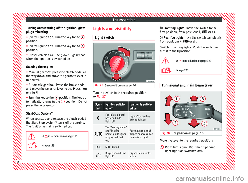
See position on page 7-8 Turn the switch to the required position
› ›
›
Fig. 27.
Sym-
bolIgnition switch-
ed offIgnition is switch-
ed on
Fog lights, dipped
beam and side
lights off.Light off or daytime
driving light on.
The “Coming home”
and “Leaving
home” guide lights
may be switched
on.Automatic control of
dipped beam and day-
time driving light.
Side light on.
Dipped beam head-
light offDipped beam switch-
ed on. Fr
ont fog lights:
mo
v
e the switch to the
first position, from positions , or .
Rear fog light: move the switch completely
from positions , or .
Switching off fog lights: Push the switch or
turn it to the position.
››› in Introduction on page 121
››› page 121 Turn signal and main beam lever
Fig. 28
See position on page 7-8 More the lever to the required position:
Right t
urn s
ignal: Right-hand parking
light (ignition switched off).
1 18
Page 30 of 248
The essentials
work hard and the outside temperature is
high, the en gine oi
l
temperature can in-
crease. This does not present any problem as
long as the warning lamps ››› table on
page 33 or ››› table on page 33 do not
appear on the display.
Additional electrical appliances ●
Operation with the windscreen wiper lever*:
Pre s
s the rocker switch ››› Fig. 35 2 until the
main menu ap pe
ars. Enter into the section
Journey data . With the rocker switch,
move to the display Convenience appli-
ances .
● Operation with the multi-function steering
whee l*:
Move with the buttons 1 or
2 to
Journey data and enter w
ith
OK . Turn the
thumbwheel to the right until the Conven-
ience appliances display appears.
In addition, a scale will inform you of the cur-
rent sum of all the additional appliances.
Saving tips Tips on how to save fuel will be displayed in
c
ondition
s
that increase fuel consumption.
Follow them to reduce consumption. The indi-
cations appear automatically only with the ef-
ficiency programme. After a time, the tips will
disappear automatically. If you wish to hide a saving tip immediately
after it
appears, press any button on the
windscreen wiper lever*/multifunction steer-
ing wheel*. Note
● If y
ou hide a saving tip, it will reappear af-
ter you switch the ignition on again.
● The saving tips do not appear in all situa-
tions, but
rather with a large separation of
time. Timer*
You can access the timer via the selection
menu
››
›
page 24.
It allows you to manually time lap times on a
racing circuit, memorise them and compare
them to the vehicle's previous best times.
The following menus can be displayed:
● Stop
● Lap
● Pause
● Partial time
● Statistics Change from one menu to another
● Vehicles without multifunction steering
wheel:
press the rocker switch in the
w ind
s
creen wiper lever.
● Vehicles with multifunction steering wheel:
pres
s or
.
Menu “Stop”
Start
The timer starts.
If there are existing laps and they are in-
cluded in the statistics, it will begin with
the number of laps in question.
It is only possible to begin with a new first
lap if the statistics have been reset first in
the Statistics
menu.
Since
startThe timer begins when the vehicle sets
off.
If the vehicle is already moving, the timer
begins once the vehicle has stopped.
Statis-
ticsThe Statistics menu is displayed on
the screen.
Menu “Lap”
New lap
The timer of the current lap stops and a
new lap starts immediately. The time for
the lap you have just completed is inclu-
ded in the statistics.
Partial timeFor about 5 seconds a partial time is dis-
played. The timer continues in parallel.
StopThe current lap timer will be interrupted.
The lap does not end. The Pause menu is
displayed. 28
Page 31 of 248
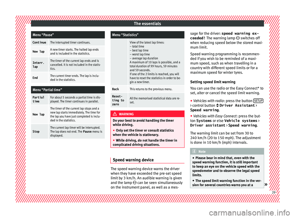
The essentialsMenu “Pause”
ContinueThe interrupted timer continues.
New lapA new timer starts. The halted lap ends
and is included in the statistics.
Interr.
lapThe timer of the current lap ends and is
cancelled. It is not included in the statis-
tics.
EndThe current timer ends. The lap is inclu-
ded in the statistics.
Menu “Partial time”
Partial
timeFor about 5 seconds a partial time is dis-
played. The timer continues in parallel.
New lap
The timer of the current lap stops and a
new lap starts immediately. The time for
the lap you have just completed is inclu-
ded in the statistics.
StopThe current lap timer will be interrupted.
The lap does not end. The Pause menu is
displayed.
Menu “Statistics”
View of the latest lap times:
– total time
– best lap time
– worst lap time
– average lap duration
A maximum of 10 laps is possible, and a
total duration of 99 hours, 59 minutes
and 59 seconds.
If one of the 2 limits is reached, you will
have to reset the statistics in order to be-
gin a new timer.
BackThis returns to the previous menu.
Reset-
ting to
zeroAll the memorised statistical data are re-
set. WARNING
Do your best to avoid handling the timer
whil e driv
ing.
● Only set the timer or consult statistics
when the vehic
le is stationary.
● While driving, do not handle the timer in
complic
ated driving situations. Speed warning device
The speed warning device warns the driver
when they
h
av
e exceeded the pre-set speed
limit by 3 km/h. An audible warning is given
and the lamp can be seen simultaneously
on the instrument panel, as well as a mes- sage for the driver: speed warning ex-
ceeded! The warning l
amp switches off
when reducing speed below the stored maxi-
mum limit.
Speed warning programming is recommen-
ded if you wish to be reminded of a maxi-
mum speed, such as when travelling in a
country with different speed limits or for a
maximum speed for winter tyres.
Setting speed limit warning
You can use the radio or the Easy Connect* to
set, alter or cancel the speed limit warning.
● Vehicles with radio : pres
s the button SETUP > control button Driver Assistant
>
Speed warning .
● Vehicles with Easy Connect : pre
s
s the but-
ton Systems or else Vehicle systems >
Driver assistant > Speed warning.
The warning limit can be set from 30 to
240 km/h (20 to 150 mph). The adjustment
is done in 10 km/h (mph) intervals. Note
● Ple a
se bear in mind that, even with the
speed warning function, it is still important
to keep an eye on the vehicle speed with the
speedometer and to observe the legal speed
limits.
● The speed limit warning function in the ver-
sion for sev
eral countries warns you at a » 29
Page 36 of 248
The essentials
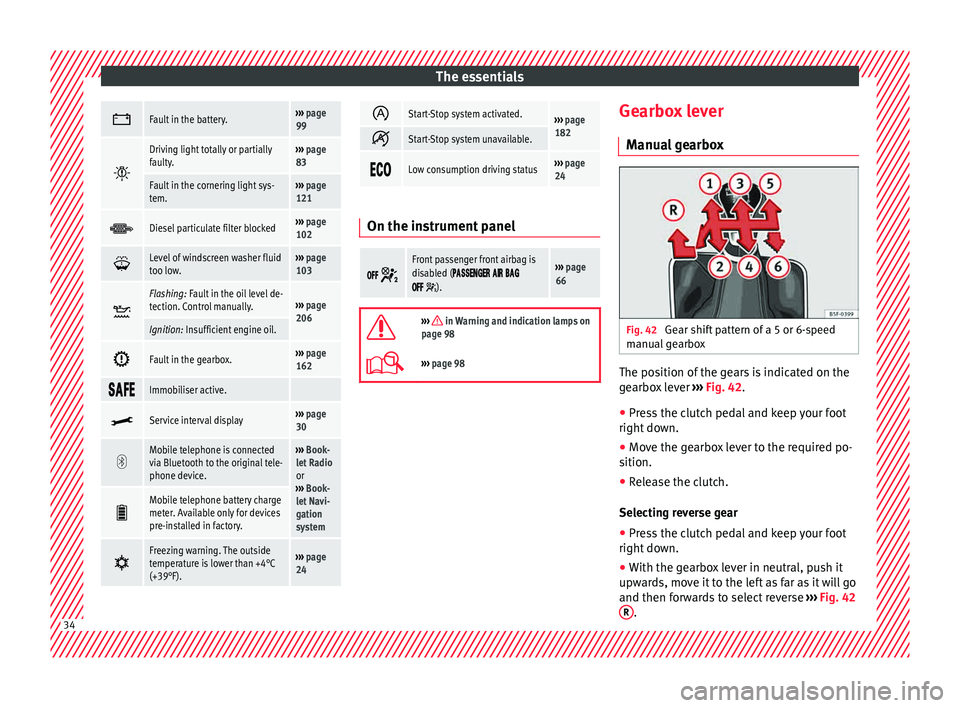
Fault in the battery.›››
page
99
Driving light totally or partially
faulty.›››
page
83
Fault in the cornering light sys-
tem.››› page
121
Diesel particulate filter blocked›››
page
102
Level of windscreen washer fluid
too low.›››
page
103
Flashing: Fault in the oil level de-
tection. Control manually.›››
page
206
Ignition: Insufficient engine oil.
Fault in the gearbox.›››
page
162
Immobiliser active.
Service interval display›››
page
30
Mobile telephone is connected
via Bluetooth to the original tele-
phone device.›››
Book-
let Radio
or
››› Book-
let Navi-
gation
system
Mobile telephone battery charge
meter. Available only for devices
pre-installed in factory.
Freezing warning. The outside
temperature is lower than +4°C
(+39°F).›››
page
24
Start-Stop system activated.›››
page
182
Start-Stop system unavailable.
Low consumption driving status›››
page
24 On the instrument panel
Front passenger front airbag is
disabled (
).
››› page
66
››› in Warning and indication lamps on
page 98
››› page 98 Gearbox lever
M anua
l
gearbox Fig. 42
Gear shift pattern of a 5 or 6-speed
m anual
g
earbox The position of the gears is indicated on the
g
e
arbo
x lever ››› Fig. 42.
● Press the clutch pedal and keep your foot
right down.
● Mo
ve the gearbox lever to the required po-
sition.
● Rel
ease the clutch.
Selecting r
everse gear
● Press the clutch pedal and keep your foot
right down.
● W
ith the gearbox lever in neutral, push it
upwar
ds, move it to the left as far as it will go
and then forwards to select reverse ››› Fig. 42
R .
34
Page 47 of 248
The essentials
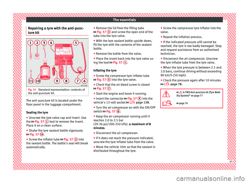
Repairing a tyre with the anti-punc-
t ur
e k
it Fig. 57
Standard representation: contents of
the anti-p u
nct
ure kit. The anti-puncture kit is located under the
floor p
anel
in the lug
gage compartment.
Sealing the tyre
● Unscrew the tyre valve cap and insert. Use
the ›››
Fig. 57 1 tool to remove the insert.
Pl ac
e it
on a clean surface.
● Shake the tyre sealant bottle vigorously
›››
Fig. 57 10 .
● Screw the inflator tube ››
›
Fig. 57 3 into
the se al
ant
bottle. The bottle's seal will break
automatically. ●
Remov
e the lid from the filling tube
››› Fig. 57 3 and screw the open end of the
t ube int
o the ty
re valve.
● With the tyre sealant bottle upside down,
fill
the tyre with the contents of the sealant
bottle.
● Remove the bottle from the valve.
● Place the insert back into the tyre valve us-
ing the too
l ››› Fig. 57 1 .
Infl atin
g the ty
re
● Screw the compressor tyre inflator tube
›››
Fig. 57 5 into the tyre valve.
● Check that the air bleed screw is closed
› ›
›
Fig. 57 7 .
● Start the engine and leave it running.
● Insert the connector ››
›
Fig. 57 9 into the
v ehic
l
e's 12-volt socket ›››
page 138.
● Turn the air compressor on with the ON/OFF
switc
h ››› Fig. 57 8 .
● Keep the air compressor running until it
r e
ac
hes 2.0 to 2.5 bar
(29-36 psi/200-250 kPa). a maximum of 8
minutes.
● Disconnect the air compressor.
● If it does not reach the pressure indicated,
uns
crew the tyre inflator tube from the valve.
● Move the vehicle 10m so that the sealant is
dis trib
uted throughout the tyre. ●
Scr ew the c
ompressor tyre inflator into the
valve.
● Repeat the inflation process.
● If the indicated pressure still cannot be
reac
hed, the tyre is too badly damaged. Stop
and request assistance from an authorised
technician.
● Disconnect the air compressor. Unscrew
the tyre infl
ator tube from the tyre valve.
● When the tyre pressure is between 2.5 and
2.0 bars, c
ontinue driving without exceeding
80 km/h (50 mph).
● Check the pressure again after 10 minutes
›››
page 78.
››› in TMS Anti-puncture kit (Tyre Mobi-
lity System)* on page 77
››› page 76 45
Page 54 of 248
The essentials
●
Ple a
se note the safety warnings referring to
working in the engine compartment
››› page 203.
● The non-insulated parts of the battery
clamp
s must not be allowed to touch. Addi-
tionally, the jump lead attached to the posi-
tive battery terminal must not touch metal
parts of the vehicle. Risk of short circuit!
● Do not connect the negative lead to the
negativ
e terminal of the discharged battery.
In the event of sparks when starting the en-
gine, the explosive gas given off by the bat-
tery could catch fire.
● Position the jump leads in such a way that
they cannot
come into contact with any mov-
ing parts in the engine compartment.
● Do not bend over the battery. Risk of acid
burns!
● The s
crew plugs on the battery cells must
be scr
ewed in firmly.
● Keep sources of fire (flames, lit cigarettes,
etc.) a
way from the battery. - Risk of explo-
sion!
● Never use the jump leads on batteries in
which the electr
olyte level is too low. Risk of
explosion and acid burns. Note
● The v ehic
les must not touch each other, as
electricity could flow as soon as the positive
terminals are connected. ●
The dis c
harged battery must be properly
connected to the vehicle electrical system.
● The jump leads should be checked in a spe-
cia
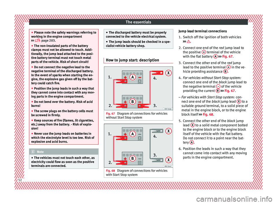
list vehicle battery shop. How to jump start: description
Fig. 67
Diagram of connections for vehicles
w ithout
Start Stop system Fig. 68
Diagram of connections for vehicles
w ith
St
art Stop system Jump lead terminal connections
1. Switch off the ignition of both vehicles
›››
.
2. Connect one end of the re
d
jump lead to
the positive + terminal of the vehicle
w ith the fl
at
battery A
› ››
Fig. 67
.
3.
Connect the other end of the red
jump
lead to the positive terminal + in the ve-
hic l
e pr
oviding assistance B .
4. For vehicles without Start-Stop system:
connect
one end of
the black jump lead to
the negative terminal – of the vehicle
pr o
v
iding the current B
› ›
› Fig. 67 .
– For vehicles with Start-Stop system: con-
nect one end of
the black jump lead X to a
s uit
ab
le ground terminal, to a solid piece of
metal in the engine block, or to the engine
block itself ››› Fig. 68.
5. Connect the other end of the black
jump
lead X to a solid metal component bolted
t o the en
gine b
lock or to the engine block
itself of the vehicle with the flat battery.
Do not connect it to a point near the bat-
tery A .
6. Position the leads in such a way that they cannot
c
ome into contact with any moving
parts in the engine compartment. 52
Page 78 of 248
Emergencies
distance. Observe applicable local legal regu-
lation
s.
This is for your own safety and that of
other drivers.
● If you have a flat tyre, stop the vehicle as
far aw
ay as possible from moving traffic. Stop
on flat, solid ground.
● If you have to change the tyre on a gradi-
ent, block
the wheel opposite the wheel be-
ing changed by placing a stone or similar ob-
ject under it to prevent the vehicle from roll-
ing away unexpectedly.
● If the vehicle has been fitted with tyres or
allo
ys that are different to those fitted in
manufacture, the instructions ››› page 217,
New tyres or wheels must be followed.
● Always raise the vehicle with the doors
closed.
● Nev
er place parts of your body, e.g. arms
and leg
s, underneath the vehicle when it is
supported only by the jack.
● Secure the base of the jack with suitable
suppor
ts so that it cannot slip. The jack could
slide if the ground below it is soft and slip-
pery and the vehicle could slip off it. There-
fore, place the jack on a firm surface or use a
large, stable base. On a slippery surface, e.g.
tile, use a non-slip base such as a rubber
mat.
● Never start the engine when the vehicle is
jack
ed. Risk of injury.
● The jack should only be used in the correct
jack
ing points. CAUTION
● The pre s
cribed tightening torque for wheel
bolts on steel and alloy wheels is 120 Nm.
● If the anti-theft wheel bolt is overly tight-
ened, this c
ould damage the bolt and the
adapter. Note
● The set of anti-thef
t wheel bolts or the
adapter are available from authorised SEAT
dealers.
● Please observe the relevant local legal reg-
ulation
s when changing the wheel. Wheel bolts
The wheel
bolts
ar
e m
atched to the rims.
When installing different wheels, e.g. to fit
light alloy wheels or wheels with winter tyres,
it is important to use the correct wheel bolts
with the right length and correctly shaped
bolt heads. This is essential for a secure fit of
the wheels and for proper operation of the
brake system. Note
● Never gr e
ase or oil the wheel bolts!
● If the wheel bolt is very tight, it may be
poss
ible to loosen it by pushing down the
end of the box spanner carefully with your foot. Hold on to the vehicle for support and
tak
e c
are not to slip.
● If you notice that the wheel bolts are rusty
and difficult
to turn when changing a wheel,
they must be replaced before having the
tightening torque checked. Tyre repairs
TMS Anti-p
uncture kit (Tyre Mobility
System)* Read the additional information carefully
› ›
›
page 45
The Tyre Mobility System is stored in a box
under the carpet in the boot.
Using the Tyre Mobility System you can relia-
bly seal tyres damaged by foreign bodies,
provided that cuts or punctures are no larger
than approx. 4 mm in diameter. Do not re-
move the foreign bodies, e.g. bolts or nails,
from the tyre!
The tyre must be repaired immediately.
The repair made using the Tyre Mobility Sys-
tem under no circumstances replaces perma-
nent tyre repair and should only be used to
drive to the nearest official service.
76
Page 95 of 248
Controls and displays
Operation
C ontr
o
ls and displays
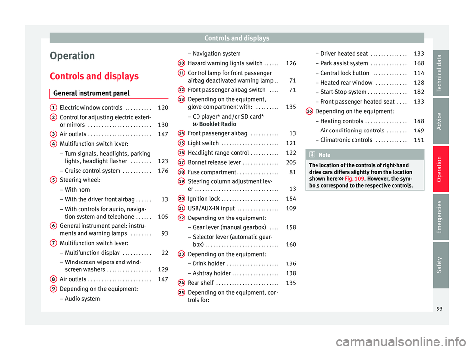
General instrument panel Electric window controls
. . . . . . . . . .120
Control for adjusting electric exteri-
or mirror s . . . . . . . . . . . . . . . . . . . . . . . . 130
Air outl
ets . . . . . . . . . . . . . . . . . . . . . . . . 147
Multifunction switch lever:
– Turn s ign
als, headlights, parking
lights, headlight flasher . . . . . . . .123
– Crui se c
ontrol system . . . . . . . . . . .176
Steering wheel:
– With horn
– With the driv
er front airbag . . . . . .13
– With c ontr
ols for audio, naviga-
tion system and telephone . . . . . .105
General instrument panel: instru-
ments and w arnin
g lamps . . . . . . . . 93
Multifunction switch lever:
– Multif
unction display . . . . . . . . . . .22
– Wind s
creen wipers and wind-
screen washers . . . . . . . . . . . . . . . . . 129
Air outlets . . . . . . . . . . . . . . . . . . . . . . . . 147
Depending on the equipment:
– Audio sy st
em
1 2
3
4
5
6
7
8
9 –
Nav ig
ation sy
stem
Hazard warning lights switch . . . . . .126
Control lamp for front passenger
airbag deactiv
ated warning lamp . .71
Front passenger airbag switch . . . .71
Depending on the equipment,
glove c
ompartment with: . . . . . . . . .135
– CD pla
yer* and/or SD card*
››› Booklet Radio
Front passenger airbag . . . . . . . . . . .13
Light switch . . . . . . . . . . . . . . . . . . . . . . 121
Headlight range control . . . . . . . . . . .122
Bonnet release lever . . . . . . . . . . . . . .205
Fuse compartment . . . . . . . . . . . . . . . . 81
Steering column adjustment lev-
er . . . . . . . . . . . . . . . . . . . . . . . . . . . . . . . . 13
Ignition lock . . . . . . . . . . . . . . . . . . . . . . 154
USB/AUX-IN input . . . . . . . . . . . . . . . . 109
Depending on the equipment: – Gear lev
er (manual gearbox) . . . .158
– Select or l
ever (automatic gear-
box) . . . . . . . . . . . . . . . . . . . . . . . . . . . . 160
Depending on the equipment:
– Drink ho l
der . . . . . . . . . . . . . . . . . . . . 136
– Ashtra y
holder . . . . . . . . . . . . . . . . . . 138
Rear shelf . . . . . . . . . . . . . . . . . . . . . . . . 135
Depending on the equipment, con-
tro l
s for:
10 11
12
13
14
15
16
17
18
19
20
21
22
23
24
25 –
Driv er he
at
ed seat . . . . . . . . . . . . . . 133
– Park a
ssist system . . . . . . . . . . . . . . 168
– Central
lock button . . . . . . . . . . . . . 114
– Heated r
ear window . . . . . . . . . . . . 128
– Start
-Stop system . . . . . . . . . . . . . . . 182
– Front p
assenger heated seat . . . .133
Depending on the equipment: – Heating c
ontrols . . . . . . . . . . . . . . . . 148
– Air conditioning c
ontrols . . . . . . . . 149
– Climatr
onic controls . . . . . . . . . . . . 151 Note
The location of the controls of right-hand
drive c ar
s differs slightly from the location
shown here ››› Fig. 109. However, the sym-
bols correspond to the respective controls. 26
93
Technical data
Advice
Operation
Emergencies
Safety