technical data Seat Toledo 2015 User Guide
[x] Cancel search | Manufacturer: SEAT, Model Year: 2015, Model line: Toledo, Model: Seat Toledo 2015Pages: 248, PDF Size: 5.06 MB
Page 73 of 248
Airbag system
Deactivating airbags D e
activ
ation of the front airbagThe disabling of airbags is only carried out in
cer
t
ain cases, i.e. if:
● a child seat is required in the front passen-
ger seat
with the child facing in the opposite
direction to the direction of travel (in some
countries, due to divergent legal require-
ments, facing in the direction of travel)
››› page 74;
● despite the driver seat being in the correct
pos ition, a minimum di
stance of 25 cm can-
not be maintained between the centre of the
steering wheel and the driver's torso,
● installation of special devices is required in
the steerin
g wheel area due to a physical dis-
ability,
● if you have special seats installed (e.g. an
orthopaedic
seat without side airbags).
The front passenger front airbag can be disa-
bled using the switch ›››
page 71.
We recommend that you contact an author-
ised SEAT dealer for the disabling of other air-
bags.
Airbag system control
The airbag system availability is controlled
electronically, regardless of whether an air-
bag is disabled. If an airbag was disabled using a diagnostics
syst
em:
● the airbag system warning lamp illumi-
n
ates after switching on the ignition for
about 4 seconds, and then flashes for about
12 seconds.
If the airbag has been disabled with the air-
bag switch on the side of the dash panel:
● the airbag control lamp wil
l illuminate
for about 4 seconds after the ignition is
switched on,
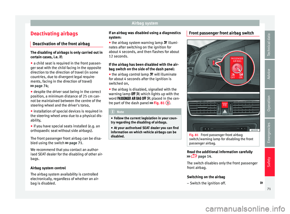
● the airbag is disabled, signalled with the
warning l
amp which lights up with the
word placed in the cen-
tre part of the dash panel ››› Fig. 81 3 .
Note
● Fo l
low the current legislation in your coun-
try regarding the disabling of airbags.
● At your authorised SEAT dealer you can find
information on whic
h vehicle airbags can be
disabled. Front passenger front airbag switch
Fig. 81
Front passenger front airbag
sw it
c
h/warning lamp for disabling the front
passenger airbag. Read the additional information carefully
› ›
›
page 14.
The switch disables only the front passenger
front airbag.
Switching on the airbag
– Switch the ignition off. »
71
Technical data
Advice
Operation
Emergencies
Safety
Page 75 of 248
Transporting children safely
Follow the manufacturer's instructions and
o b
ser
ve any statutory requirements when in-
stalling and using child seats. Always read
and note ››› page 73.
We recommend you always carry the manu-
facturer's Child Seat Instruction Manual to-
gether with the on-board documentation.
Important information regarding the
front p
assenger's airbag Read the additional information carefully
› ›
›
page 16.
Read and always observe the safety informa-
tion included in the following chapters:
● Safety distance with respect to the passen-
ger airbag ›
›› page 66, Why is it so important
to wear a seat belt and to sit correctly? .
● Objects between the passenger and the
pas
senger side airbag ››› in Front airbags
on p ag
e 69
.
The passenger side front airbag, when ena-
bled, is a serious risk for a child that is facing
backward since the airbag can strike the seat
with such force that it can cause serious or
fatal injuries. Children up to 12 years old
should always travel on the rear seat.
Therefore we strongly recommend you to
transport children on the rear seats. This is
the safest location in the vehicle. Alternative- ly, the front passenger airbag can be disa-
bled w
ith a key-operated switch ››› page 71.
When transporting children, use a child seat
suitable for the age and size of each child
››› page 72. WARNING
● If a c hi
ld seat is secured to the front pas-
senger seat, the risk to the child of sustain-
ing critical or fatal injuries in the event of an
accident increases.
● An inflating front passenger airbag can
strike the r
ear-facing child seat and project it
with great force against the door, the roof or
the backrest.
● Never install a child seat facing backwards
on the front p
assenger seat unless the front
passenger front airbag has been disabled.
Risk of potentially fatal injuries to the child!
However, if it is necessary, in exceptional ca-
ses, to transport a child in the front passen-
ger seat, the front passenger front airbag
must always be disabled ››› page 71. If the
front passenger seat has a height adjustment
option, move it to the highest position.
● For those vehicles that do not include a key
lock sw
itch to deactivate the airbag, the vehi-
cle must be taken to a technical service.
● All vehicle occupants, especially children,
must
assume the proper sitting position and
be properly belted in while travelling.
● Never hold children or babies on your lap,
this c
an result in potentially fatal injuries to
the child! ●
Never a l
low a child to be transported in a
vehicle without being properly secured, or to
stand up or kneel on a seat while travelling.
In an accident, the child could be flung
through the vehicle, causing possibly fatal in-
juries to themselves and to the other vehicle
occupants.
● If children assume an improper sitting posi-
tion when the vehic
le is moving, they expose
themselves to greater risk of injury in the
event of a sudden braking manoeuvre or in an
accident. This is particularly important if the
child is travelling on the front passenger seat
and the airbag system is triggered in an acci-
dent; as this could cause serious injury or
even death.
● A suitable child seat can protect your child!
● Never leave a child alone in the child seat
or inside the
vehicle because depending on
the season, very high temperatures may be
reached inside a parked vehicle, which could
be fatal.
● Children who are less than 1.5 metres tall
must
not wear a normal seat belt without a
child seat, as this could cause injuries to the
abdominal and neck areas during a sudden
braking manoeuvre or in an accident.
● Only one child may occupy a child seat
›››
page 74, Child seats. 73
Technical data
Advice
Operation
Emergencies
Safety
Page 77 of 248
Self-help
Emergencies
Self -help
Emer g
ency equipment
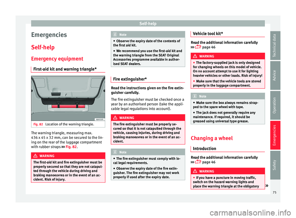
First-aid kit and warning triangle* Fig. 82
Location of the warning triangle. The warning triangle, measuring max.
436 x 45 x 32 mm, c
an be sec
ur
ed to the lin-
ing on the rear of the luggage compartment
with rubber straps ››› Fig. 82. WARNING
The first-aid kit and fire extinguisher must be
properly sec
ured so that they are not catapul-
ted through the vehicle during driving and
braking manoeuvres or in the event of an ac-
cident. Risk of injury. Note
● Ob ser
ve the expiry date of the contents of
the first aid kit.
● We recommend you use the first-aid kit and
the warning tri
angle from the SEAT Original
Accessories programme available in author-
ised SEAT dealers. Fire extinguisher*
Read the instructions given on the fire extin-
gui
sher c
ar
efully.
The fire extinguisher must be checked once a
year by an authorised person (take the appli-
cable legal regulations into account). WARNING
The fire extinguisher must be properly se-
cur ed so th
at it is not catapulted through the
vehicle, causing injuries, during driving and
braking manoeuvres or in the event of an ac-
cident. Note
● The fire e xtin
guisher must comply with lo-
cal legal requirements.
● Observe the expiry date of the fire extin-
guisher.
The fire extinguisher may not work
properly if used after the expiry date. Vehicle tool kit*
Read the additional information carefully
›› ›
page 46 WARNING
● The fact or
y-supplied jack is only designed
for changing wheels on this model of vehicle.
On no account attempt to use it for lighting
heavier vehicles or other loads. Risk of injury!
● Make sure that the vehicle tools are stored
properly in the lug
gage compartment. Note
● Mak e s
ure the box always remains strap-
ped to the spare wheel with tape.
● The jack does not generally require any
mainten
ance. If required, it should be
greased using universal type grease. Changing a wheel
Intr oduction Read the additional information carefully
› ›
›
page 46 WARNING
● If y
ou have a puncture in moving traffic,
switch on the hazard warning lights and
place the warning triangle at the obligatory » 75
Technical data
Advice
Operation
Emergencies
Safety
Page 79 of 248
Self-help
The Tyre Mobility System kit shall not be
u sed:
● If the wheel
rim has been damaged,
● when the outside temperature is below
-20°C (-4°F),
● on sl
ashes or punctures larger than 4 mm,
● if the sidewall of the wheel has been dam-
aged,
● If
you have been driving with very low tyre
pres
sure or a completely flat tyre
● If the best-before date on the air can has
expired WARNING
Using the tyre mobility system can be dan-
ger ou
s, especially when filling the tyre at the
roadside. Please observe the following rules
to minimise the risk of injury:
● Stop the vehicle safely as soon as possible.
Park it
at a safe distance from surrounding
traffic to fill the tyre.
● Ensure the ground on which you park is flat
and solid.
● Al
l passengers and particularly children
must
keep a safe distance from the work area.
● Turn on the hazard warning lights to warn
other roa
d users.
● Use the tyre mobility system only if you are
famili
ar with the necessary procedures. Oth-
erwise, you should seek professional assis-
tance. ●
The tyr e mo
bility set is intended for tempo-
rary emergency use only until you can reach
the nearest specialised workshop.
● Replace the repaired tyre with the tyre mo-
bility
set as soon as possible.
● The sealant is a health hazard and must be
cle
aned immediately if it comes into contact
with the skin.
● Always keep the tyre mobility set out of the
reac
h of small children.
● Never use an equivalent jack, even if it has
been appro
ved for your vehicle.
● Always stop the engine, apply the hand-
brake l
ever firmly and engage gear if using a
manual gearbox, in order to reduce the risk of
vehicle involuntary movement. WARNING
A tyre filled with sealant does not have the
same per f
ormance properties as a conven-
tional tyre.
● Never drive faster than 80 km/h (50 mph).
● Avoid heavy acceleration, hard braking and
fas
t cornering.
● Drive for only 10 minutes at a maximum
speed of 80
km/h (50 mph) and then check
the tyre. For the sake of the environment
Dispose of used or expired sealant observing
any l
egal requirements. Note
● A new bottle of se
alant can be purchased at
SEAT dealerships.
● Take into account the separate instruction
manual
of the tyre mobility set* manufactur-
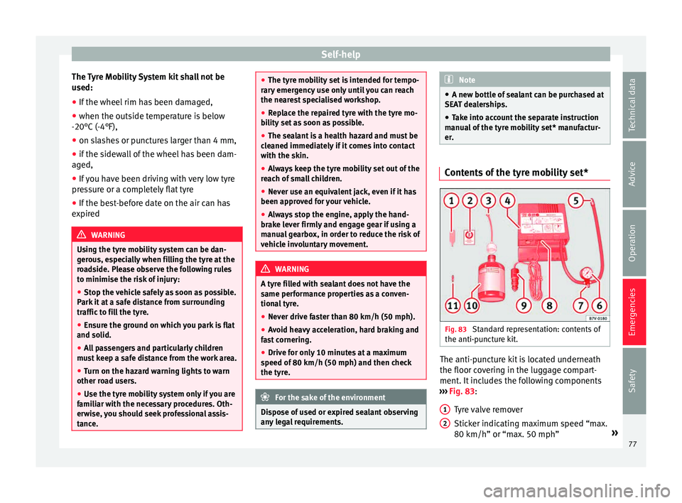
er. Contents of the tyre mobility set*
Fig. 83
Standard representation: contents of
the anti-p u
nct
ure kit. The anti-puncture kit is located underneath
the floor c
o
v
ering in the luggage compart-
ment. It includes the following components
››› Fig. 83:
Tyre valve remover
Sticker indicating maximum speed “max.
80 km/h” or “max. 50 mph” »
1 2
77
Technical data
Advice
Operation
Emergencies
Safety
Page 81 of 248
Self-help
CAUTION
● Do not t o
w-start the engine. Risk of engine
damage! In vehicles with a catalytic convert-
er, fuel that has not been burned could reach
the catalytic converter and catch fire in it.
This could damage and destroy the catalytic
converter. You may use the battery from an-
other vehicle to help you start your engine
››› page 52.
● If, due to a fault, there is no oil in the gear-
box, the car m
ay only be towed with the driv-
en wheels lifted clear of the road and trans-
ported on a special vehicle transporter or
trailer.
● If normal towing is not possible or if the ve-
hicle i
s to be towed for further than 50 km,
the vehicle must be transported on a special
vehicle transporter or trailer.
● The towrope should be slightly elastic to
reduce the lo
ad on both vehicles during tow-
ing. It is advisable to use a towrope made of
synthetic fibre or similar material only.
● Do not pull too hard with the towing vehicle
and alwa
ys take care to avoid jerking the tow-
rope. When towing on a loose surface there is
always a risk of overloading and damaging
the anchorage points.
● Attach the towrope or towbar only to the
towline anc
horages or to the removable tow-
ing bracket ››› page 185, or ››› page 79. Note
● We r ec
ommend you use the towrope or tow-
bar available in the SEAT Original Accessories
programme from authorised SEAT dealers.
● Towing a vehicle requires a certain degree
of practic
al skill. Both drivers should be fa-
miliar with the technique required for towing.
Inexperienced drivers should not attempt to
tow away another vehicle or to have their ve-
hicle towed.
● Note the legal regulations concerning tow-
ing, par
ticularly those regarding the signal-
ling of the towed and towing vehicle.
● The towrope must not be twisted, as under
cert
ain circumstances this could unscrew the
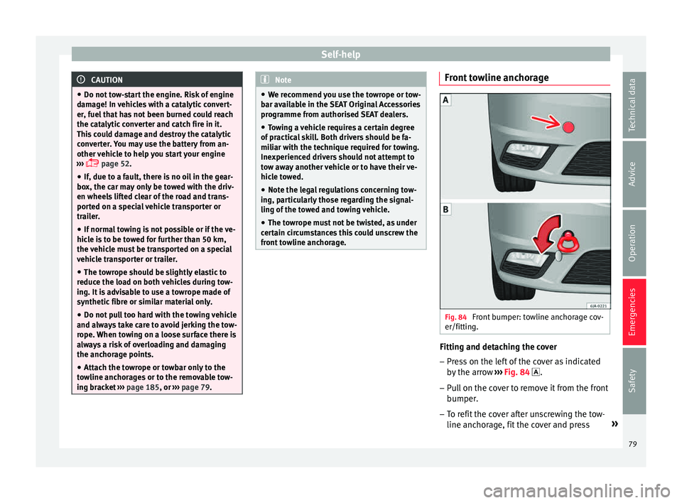
front towline anchorage. Front towline anchorage
Fig. 84
Front bumper: towline anchorage cov-
er/fittin g. Fitting and detaching the cover
– Press on the left of the cover as indicated
by
the arr
ow ››› Fig. 84 .
– Pull on the cover to remove it from the front
bumper.
– T
o refit the cover after unscrewing the tow-
line anchorag
e, fit the cover and press »
79
Technical data
Advice
Operation
Emergencies
Safety
Page 83 of 248
Fuses and bulbs
●
Prot ect
the fuse boxes when open to pre-
vent the entry of dust or humidity as they can
damage the electrical system.
● Always carefully remove the fuse box cov-
ers and r
efit them correctly to avoid problems
with your vehicle. Note
● One c omponent m
ay have more than one
fuse.
● Several components may run on a single
fuse.
● In the
vehicle, there are more fuses than
those indicat
ed in this chapter. These should
only be changed by a specialised workshop.
● Positions not containing a fuse do not ap-
pear in the fo
llowing tables.
● Some of the equipment listed in the tables
below pert
ain only to certain versions of the
model or are optional extras.
● Please note that the above lists, while cor-
rect at
the time of printing, are subject to
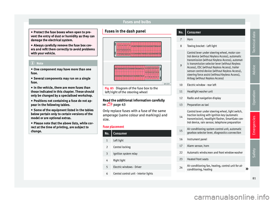
change. Fuses in the dash panel
Fig. 85
Diagram of the fuse box to the
l ef
t/right
of the steering wheel Read the additional information carefully
› ›
›
page 43
Only replace fuses with a fuse of the same
amperage (same colour and markings) and
size.
Fuse placement
No.Consumer
1Left light
2Central locking
3Ignition system relay
4Right light
5Electric windows - Driver
6Central control unit - Interior lights
No.Consumer
7Horn
8Towing bracket - Left light
9
Control lever under steering wheel, motor con-
trol device (without Keyless Access), automatic
transmission (without Keyless Access), automat-
ic transmission selector lever (without Keyless
Access), ESC (without Keyless Access), trailer
sensor control device (without Keyless Access),
steering force assist (without Keyless Access),
Airbag (without Keyless Access)
10Electric window - rear left
11Headlight washer unit
12Radio and navigation display
13Preparation as taxi
14
Control lever under steering wheel, light switch,
traction locking with ignition key (automatic
transmission), headlight flasher, SmartGate con-
trol device, rain sensor, telephone preparation
15Air conditioning system control unit, automatic
gearbox selector lever, diagnostics connection
16Instrument panel
17Alarm sensor, horn
22Automatic windscreen and front window washer
23Heated front seats
24Air conditioning fan, heating, control unit for air
conditioning, heating» 81
Technical data
Advice
Operation
Emergencies
Safety
Page 85 of 248
Fuses and bulbs
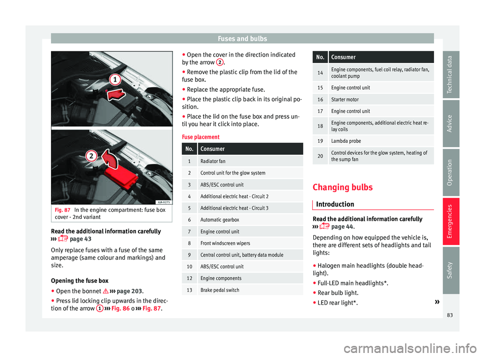
Fig. 87
In the engine compartment: fuse box
c o
v
er - 2nd variant Read the additional information carefully
› ›
›
page 43
Only replace fuses with a fuse of the same
amperage (same colour and markings) and
size.
Opening the fuse box ● Open the bonnet ›››
page 203.
● Press lid locking clip upwards in the direc-
tion of the arro
w 1
› ›
› Fig. 86 o ››› Fig. 87. ●
Open the cov
er in the direction indicated
by the arrow 2 .
● Remove the plastic clip from the lid of the
f u
se bo
x.
● Replace the appropriate fuse.
● Place the plastic clip back in its original po-
sition.
● Plac
e the lid on the fuse box and press un-
til
you hear it click into place.
Fuse placement
No.Consumer
1Radiator fan
2Control unit for the glow system
3ABS/ESC control unit
4Additional electric heat - Circuit 2
5Additional electric heat - Circuit 3
6Automatic gearbox
7Engine control unit
8Front windscreen wipers
9Central control unit, battery data module
10ABS/ESC control unit
12Engine components
13Brake pedal switch
No.Consumer
14Engine components, fuel coil relay, radiator fan,
coolant pump
15Engine control unit
16Starter motor
17Engine control unit
18Engine components, additional electric heat re-
lay coils
19Lambda probe
20Control devices for the glow system, heating of
the sump fan Changing bulbs
Intr oduction Read the additional information carefully
› ›
›
page 44.
Depending on how equipped the vehicle is,
there are different sets of headlights and tail
lights:
● Halogen main headlights (double head-
light).
● Full-LED main headlights*.
● Rear bulb light.
● LED rear light*. »
83
Technical data
Advice
Operation
Emergencies
Safety
Page 87 of 248
Fuses and bulbs
Dipped beam headlights
T urn s
ign
al lights
Daylight
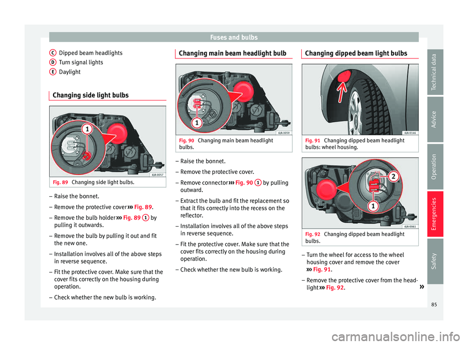
Changing side light bulbs Fig. 89
Changing side light bulbs. –
Raise the bonnet.
– Remove the protective cover ›
› ›
Fig. 89.
– Remove the bulb holder ›››
Fig. 89 1 by
p u
l
ling it outwards.
– Remove the bulb by pulling it out and fit
the new one.
– Installation involves all of the above steps
in rever
se sequence.
– Fit the protective cover. Make sure that the
cov
er fits correctly on the housing during
operation.
– Check whether the new bulb is working.
C D
E Changing main beam headlight bulb
Fig. 90
Changing main beam headlight
b u
l
bs. –
Raise the bonnet.
– Remove the protective cover.
– Remove connector ››
›
Fig. 90 1 by pulling
outw ar
d.
– Extr
act the bulb and fit the replacement so
that it
fits correctly into the recess on the
reflector.
– Installation involves all of the above steps
in rever
se sequence.
– Fit the protective cover. Make sure that the
cov
er fits correctly on the housing during
operation.
– Check whether the new bulb is working. Changing dipped beam light bulbs
Fig. 91
Changing dipped beam headlight
b u
l
bs: wheel housing. Fig. 92
Changing dipped beam headlight
b u
l
bs. –
Turn the wheel for access to the wheel
hou s
in
g cover and remove the cover
››› Fig. 91.
– Remove the protective cover from the head-
light ››
› Fig. 92. »
85
Technical data
Advice
Operation
Emergencies
Safety
Page 89 of 248
Fuses and bulbs
– Remo
v
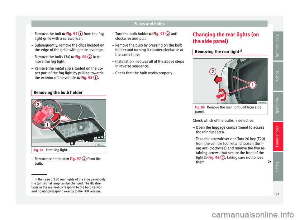
e the bolt ››› Fig. 95 1 from the fog
light gri
l
le with a screwdriver.
– Subsequently, remove the clips located on
the edge of the gri
lle with gentle leverage.
– Remove the bolts (3x) ›››
Fig. 96 2 to re-
mo v
e the f
og light.
– Remove the metal clip situated on the up-
per part
of the fog light by pulling towards
the exterior of the vehicle ››› Fig. 96 3 .
Removing the bulb holder Fig. 97
Front fog light. –
Remove connector ››
›
Fig. 97 1 from the
b u
l
b. –
Turn the bu
lb holder ››› Fig. 97 2 anti-
c loc
k
wise and pull.
– Remove the bulb by pressing on the bulb
holder and t
urning it counter-clockwise at
the same time.
– Installation involves all of the above steps
in rever
se sequence.
– Check that the bulb works properly. Changing the rear lights (on
the side panel)
R
emoving the rear light 1) Fig. 98
Remove the rear light unit from side
p anel
. Check which of the bulbs is defective.
– Open the luggage compartment to access
the r ainduct
ar
ea.
– Take the screwdriver or a Torx 20 key (T20)
from the v
ehicle tool kit and loosen (turn-
ing anti-clockwise) and remove the two re-
taining screws that secure the front of the
light ›››
Fig. 98 1 , taking care not to lose
them. »1)
In the case of LED rear lights of the side panel only
the turn s ign
al lamp can be changed. The illustra-
tions in the manual correspond to the bulb version
and do not correspond exactly to the LED version. 87
Technical data
Advice
Operation
Emergencies
Safety
Page 91 of 248
Fuses and bulbs
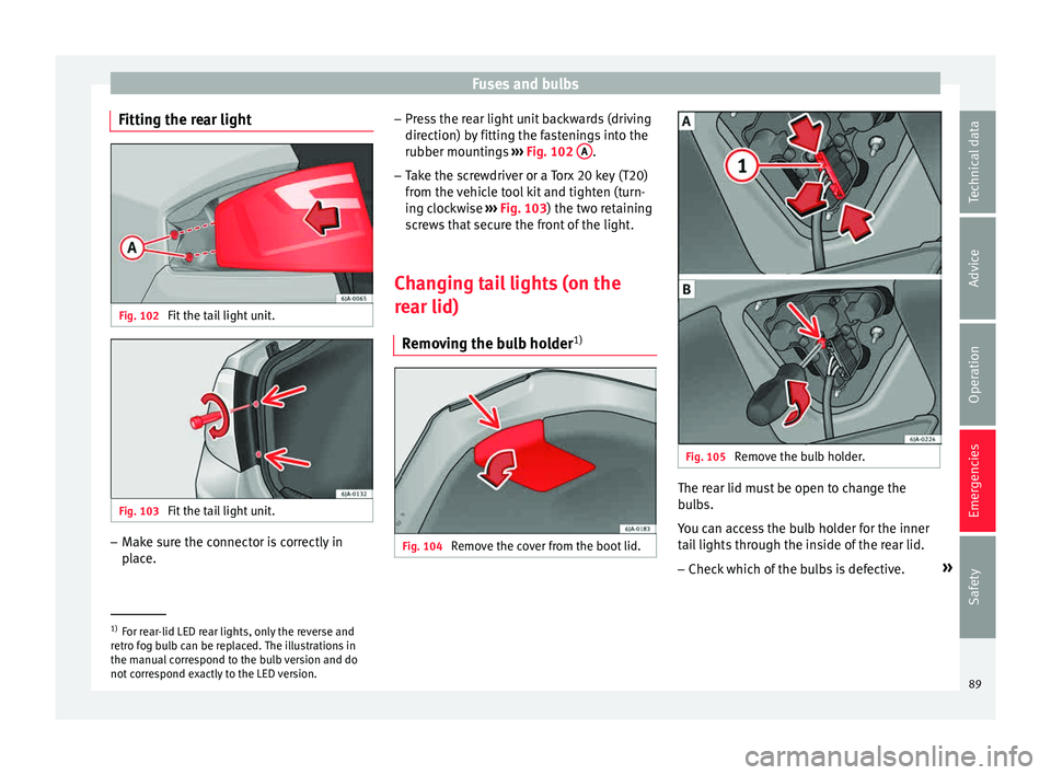
Fitting the rear light Fig. 102
Fit the tail light unit. Fig. 103
Fit the tail light unit. –
Make sure the connector is correctly in
pl
ac
e. –
Pres
s the rear light unit backwards (driving
direction) by fitting the fastenings into the
rubber mountings ››› Fig. 102 A .
– Take the screwdriver or a Torx 20 key (T20)
from the
v
ehicle tool kit and tighten (turn-
ing clockwise ››› Fig. 103) the two retaining
screws that secure the front of the light.
Changing tail lights (on the
rear lid) R
emoving the bulb holder 1) Fig. 104
Remove the cover from the boot lid. Fig. 105
Remove the bulb holder. The rear lid must be open to change the
b
u
l
bs.
You can access the bulb holder for the inner
tail lights through the inside of the rear lid.
– Check which of the bulbs is defective. »1)
For rear-lid LED rear lights, only the reverse and
retr o f
og bulb can be replaced. The illustrations in
the manual correspond to the bulb version and do
not correspond exactly to the LED version. 89
Technical data
Advice
Operation
Emergencies
Safety