steering Seat Toledo 2016 User Guide
[x] Cancel search | Manufacturer: SEAT, Model Year: 2016, Model line: Toledo, Model: Seat Toledo 2016Pages: 248, PDF Size: 5.82 MB
Page 33 of 248
The essentials
Reading a service notification
W ith the ignition sw
it
ched on, the engine off
and the vehicle at a standstill, the current
service notification can be read:
Press and hold the button 4 for more than 5
sec ond
s
to consult the service message.
When the service date has passed , a minus
sign is displayed in front of the number of kil-
ometres or days.
Vehicles with text messages : Service
since --- km or --- days ago will be
shown on the display.
The time can also be set via the key and
Set up function button in the Easy Connect
sy s
t
em ›››
page 99.
Resetting service interval display
If the service was not carried out by a SEAT
dealership, the display can be reset as fol-
lows:
● Switch off the ignition, press and hold but-
ton ››
› Fig. 110
4 .
● Switch ignition back on.
● Release the 4
› ›
›
Fig. 110
button and
press it again for the next 20 seconds. Note
● The serv ic
e message disappears after a few
seconds, when the engine is started or when OK/RESET
is pressed on the windscreen wiper
lev er
, or OK on the multifunction steering
wheel.
● In v
ehicles with the LongLife system in
which the batt
ery has been disconnected for
a long period of time, it is not possible to cal-
culate the date of the next service. Therefore
the service interval display may not be cor-
rect. In this case, bear in mind the maximum
service intervals permitted in the ››› Book-
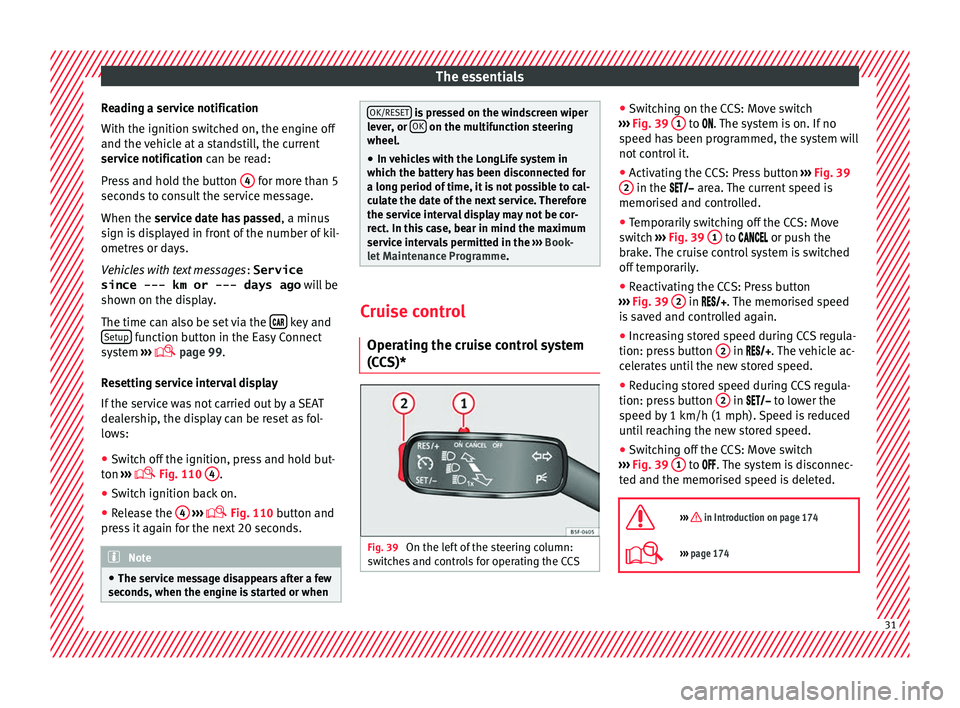
let Maintenance Programme. Cruise control
Oper atin
g the c
ruise control system
(CCS)* Fig. 39
On the left of the steering column:
sw it
c
hes and controls for operating the CCS ●
Sw it
c
hing on the CCS: Move switch
››› Fig. 39 1 to .
The system is on. If no
s peed h
as been programmed, the system will
not control it.
● Activating the CCS: Press button ›››
Fig. 39
2 in the ar
e
a. The current speed is
memorised and controlled.
● Temporarily switching off the CCS: Move
switc
h ››› Fig. 39 1 to
or push the
br ak
e. The cruise control system is switched
off temporarily.
● Reactivating the CCS: Press button
›››
Fig. 39 2 in
. The memorised speed
i
s saved and controlled again.
● Increasing stored speed during CCS regula-
tion: pres
s button 2 in
. The vehicle ac-
c
elerates until the new stored speed.
● Reducing stored speed during CCS regula-
tion: pres
s button 2 in t
o lower the
s peed b
y 1 km/h (1 mph). Speed is reduced
until reaching the new stored speed.
● Switching off the CCS: Move switch
›››
Fig. 39 1 to .
The system is disconnec-
t ed and the memori
sed speed is deleted.
››› in Introduction on page 174
››› page 174 31
Page 34 of 248
The essentials
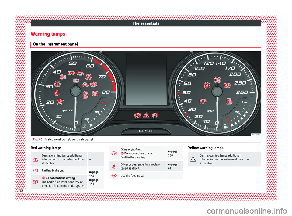
Warning lamps On the in s
trument
panelFig. 40
Instrument panel, on dash panel Red warning lamps
Central warning lamp: additional
information on the instrument pan-
el display–
Parking brake on.›››
page
154
››› page
153
Do not continue driving!
The brake fluid level is too low or
there is a fault in the brake system.
Lit up or flashing: Do not continue driving!
Fault in the steering.››› page
150
Driver or passenger has not fas-
tened seat belt.›››
page
61
Use the foot brake! Yellow warning lamps
Central warning lamp: additional
information on the instrument pan-
el display–
32
Page 35 of 248
The essentials
Front brake pads worn.
›››
page
154
it lights up:
Fault in the ESC, or dis-
connection caused by the system.
flashes: ESC or ASR activated.
ASR manually deactivated.
ABS faulty or does not work.
Rear fog light switched on.›››
page
18
lights up or flashes:
fault in the
emission control system.››› page
164
it lights up:
pre-heating of diesel
engine.
››› page
165
flashes: fault in the diesel engine
management.
fault in the petrol engine manage-
ment.›››
page
165
lights up or flashes:
fault in the
steering system.››› page
150
Tyre pressure too low, or fault in
the tyre pressure monitoring sys-
tem.›››
page
219
Fuel tank almost empty.›››
page
98
Fault in airbag system and seat
belt tensioners.›››
page
66 Other warning lamps
Left or right turn signal.›››
page
19
Hazard warning lights on.››› page
121
Trailer turn signals›››
page
184
it lights up:
Press the foot brake!
flashes: the selector lever locking
button has not engaged.››› page
157
it lights up:
cruise control activated
or speed limiter switched on and
active.
››› page
31
flashes: the speed set by the
speed limiter has been exceeded.
Main beam on or flasher on.›››
page
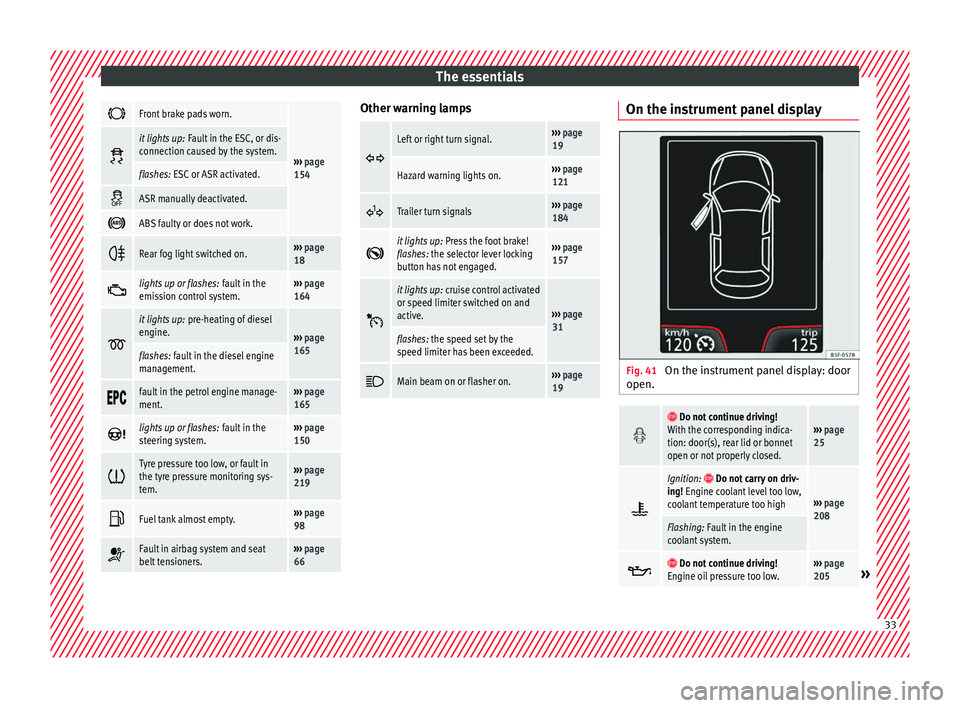
19 On the instrument panel display
Fig. 41
On the instrument panel display: door
open.
Do not continue driving!
With the corresponding indica-
tion: door(s), rear lid or bonnet
open or not properly closed.››› page
25
Ignition: Do not carry on driv-
ing! Engine coolant level too low,
coolant temperature too high
››› page
208
Flashing: Fault in the engine
coolant system.
Do not continue driving!
Engine oil pressure too low.››› page
205» 33
Page 53 of 248
The essentials
Notes for the driver of the towing vehicle
● The tow rope must be taut before you drive
off .
● Rel
ease the clutch very carefully when start-
ing the v
ehicle (manual gearbox), or acceler-
ate gently (automatic gearbox).
Driving style
Towing requires some experience, especially
when using a tow rope. Both drivers should
realise how difficult it is to tow a vehicle. In-
experienced drivers should not attempt to
tow.
Do not pull too hard with the towing vehicle
and take care to avoid jerking the tow rope.
When towing on an unpaved road, there is al-
ways a risk of overloading and damaging the
anchorage points.
The towline anchorages are located under
the floor panel in the luggage compartment.
Switch on the ignition so that the turn sig-
nals, windscreen wipers and windscreen
washer can work. Ensure that the steering
wheel is unlocked and moves freely.
Place the gear lever in neutral on vehicles
with a manual gearbox. With an automatic
gearbox, place the lever in N.
To brake, press the brake pedal firmly. The
brake servo does not work when the engine
is switched off. The power steering only works when the igni-
tion is sw
itched on and the vehicle is moving,
provided that the battery is sufficiently charg-
ed. Otherwise, it will need more force.
Ensure that the tow rope remains taut at all
times.
››› page 78 Tow-starting
If the engine will not start, first try starting it
u
s
in
g the battery of another vehicle
››› page 51. You should only attempt to tow-
start a vehicle if charging the battery does
not work. This is done by leveraging wheel
movement.
When tow-starting a vehicle with a petrol en-
gine, do not tow it more than a short dis-
tance, otherwise unburned fuel can enter the
catalytic converter.
● Engage 2nd or 3rd gear before moving off.
● Press the clutch and hold the pedal down.
● Switch the ignition on.
● Once both vehicles are moving, release the
clutc
h.
● As soon as the engine has started, press
the clutc
h and move the gear lever to neutral. How to jump start
Jump lea
ds The jump lead must have a sufficient wire
cr
o
ss section.
If the engine fails to start because of a dis-
charged battery, the battery can be connec-
ted to the battery of another vehicle to start
the engine.
Both batteries need to have nominal voltage
of 12 V. The capacity (Ah) of the back-up bat-
tery should not be notably less than the
drained battery.
Jump leads must comply with standard DIN
72553 (see cable manufacturer's instruc-
tions). The wire cross section must be at least
25 mm 2
for petrol engines and at least
35 mm 2
for diesel engines.
Jump leads
Positive cable – usually red
Negative cable – usually black WARNING
● A flat b
attery can also freeze at tempera-
tures slightly below to 0°C (32°F). Do not at-
tempt to start the vehicle with a frozen bat-
tery. Risk of explosion! » 51
Page 58 of 248
Safety
risk of injury. The following list includes most
of the s
af
ety equipment in your SEAT:
● three-point seat belts,
● belt tension limiters for the front and rear
side seats,
● belt
tensioners for the front seats,
● belt height adjustment for the front seats,
● front airbags,
● side airbags in the front seat backrests,
● side airbags in the rear seat backrests*,
● head-protection airbags,
● active front head restraints*,
● “ISOFIX” anchor points for child seats in
the rear s
ide seats with the “ISOFIX” system,
● height-adjustable front head restraints,
● rear head restraints with in-use position
and non-use pos
ition,
● adjustable steering column.
The safety
equipment mentioned above
works together to provide you and your pas-
sengers with the best possible protection in
the event of an accident. However, these
safety systems can only be effective if you
and your passengers are sitting in a correct
position and use this equipment properly.
Safety is everyone's business! Correct position for passengers
Correct
sitting position for driver Fig. 71
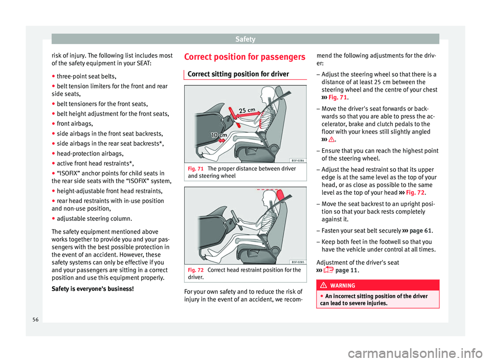
The proper distance between driver
and s t
eerin
g wheel Fig. 72
Correct head restraint position for the
driv er
. For your own safety and to reduce the risk of
injur
y
in the ev
ent of an accident, we recom- mend the following adjustments for the driv-
er:
– Adjust the steering wheel so that there is a
dist
ance of at least 25 cm between the
steering wheel and the centre of your chest
››› Fig. 71.
– Move the driver's seat forwards or back-
ward
s so that you are able to press the ac-
celerator, brake and clutch pedals to the
floor with your knees still slightly angled
››› .
– Ensure that you can reach the highest point
of the s
t
eering wheel.
– Adjust the head restraint so that its upper
edge is
at the same level as the top of your
head, or as close as possible to the same
level as the top of your head ››› Fig. 72.
– Move the seat backrest to an upright posi-
tion so that
your back rests completely
against it.
– Fasten your seat belt securely ›››
page 61.
– Keep both feet in the footwell so that you
have the
vehicle under control at all times.
Adjustment of the driver's seat
››› page 11. WARNING
● An incorr ect
sitting position of the driver
can lead to severe injuries. 56
Page 59 of 248
Safe driving
●
Adjus t
the driver's seat so that there is at
least 25 cm distance between the centre of
the chest and the centre of the steering
wheel ››› Fig. 71. If you are sitting closer than
25 cm, the airbag system cannot protect you
properly.
● If your physical constitution prevents you
from maint
aining the minimum distance of 25
cm, contact a specialised workshop. The
workshop will help you decide if special spe-
cific modifications are necessary.
● When driving, always hold the steering
wheel with both h
ands on the outside of the
ring at the 9 o'clock and 3 o'clock positions.
This reduces the risk of injury when the driver
airbag is triggered.
● Never hold the steering wheel at the 12
o'clock
position, or in any other manner (e.g.
in the centre of the steering wheel). In such
cases, if the airbag is triggered, you may sus-
tain injuries to the arms, hands and head.
● To reduce the risk of injury to the driver
during sud
den braking manoeuvres or an ac-
cident, never drive with the backrest tilted far
back! The airbag system and seat belts can
only provide optimal protection when the
backrest is in an upright position and the
driver is wearing his or her seat belt correct-
ly.
● Adjust the head restraint properly to ach-
ieve optima
l protection. Adjusting the steering wheel position
Read the additional information carefully
›› ›
page 13. WARNING
● Never a dju
st the position of the steering
wheel when the vehicle is moving, as this
could cause an accident.
● Move the lever up firmly so the steering
wheel pos
ition does not accidentally change
during driving. risk of accident!
● Make sure you are capable of reaching and
firmly ho
lding the upper part of the steering
wheel: risk of accident!
● If you adjust the steering wheel so that it
points t
owards your face, the driver airbag
will not protect you properly in the event of
an accident. Make sure that the steering
wheel points towards your chest. Correct sitting position for front pas-
sen
g
er For your own safety and to reduce the risk of
injur
y
in the ev
ent of an accident, we recom-
mend the following adjustments for the front
passenger:
– Move the front passenger seat back as far
as po
ssible ››› .–
Mo v
e the se
at backrest to an upright posi-
tion so that your back rests completely
against it.
– Adjust the head restraint so that its upper
edge is
at the same level as the top of your
head, or as close as possible to the same
level as the top of your head ››› page 59.
– Always keep both feet in the footwell in
front of
the front passenger seat.
– Fasten your seat belt securely ›››
page 61.
It is possible to deactivate the front passen-
ger airbag in exceptional circumstances
››› page 71.
Adjusting the front passenger seat
››› page 11. WARNING
● An incorr ect
sitting position of the front
passenger can lead to severe injuries.
● Adjust the front passenger seat so that
there is
at least 25 cm between your chest
and the dash panel. If you are sitting closer
than 25 cm, the airbag system cannot protect
you properly.
● If your physical constitution prevents you
from maint
aining the minimum distance of 25
cm, contact a specialised workshop. The
workshop will help you decide if special spe-
cific modifications are necessary. » 57
Technical data
Advice
Operation
Emergencies
Safety
Page 65 of 248
Seat belts
Physical principles of a frontal colli-
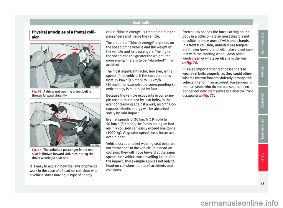
s ion Fig. 76
A driver not wearing a seat belt is
thr o
wn f
orward violently Fig. 77
The unbelted passenger in the rear
se at
i
s thrown forward violently, hitting the
driver wearing a seat belt It is easy to explain how the laws of physics
w
ork
in the c
ase of a head-on collision: when
a vehicle starts moving, a type of energy called “kinetic energy” is created both in the
pas
sengers and inside the vehicle.
The amount of “kinetic energy” depends on
the speed of the vehicle and the weight of
the vehicle and its passengers. The higher
the speed and the greater the weight, the
more energy there is to be “absorbed” in an
accident.
The most significant factor, however, is the
speed of the vehicle. If the speed doubles
from 25 km/h (15 mph) to 50 km/h
(30 mph), for example, the corresponding ki-
netic energy is multiplied by four.
Because the vehicle occupants in our exam-
ple are not restrained by seat belts, in the
event of crashing against a wall, all of the oc-
cupants' kinetic energy will be absorbed
solely by said impact.
Even at speeds of 30 km/h (19 mph) to
50 km/h (30 mph), the forces acting on bod-
ies in a collision can easily exceed one tonne
(1000 kg). At greater speed these forces are
even higher.
Vehicle occupants not wearing seat belts are
not “attached” to the vehicle. In a head-on
collision, they will move forward at the same
speed their vehicle was travelling just before
the impact. This example applies not only to
head-on collisions, but to all accidents and
collisions. Even at low speeds the forces acting on the
body in a co
llision are so great that it is not
possible to brace oneself with one's hands.
In a frontal collision, unbelted passengers
are thrown forward and will make violent con-
tact with the steering wheel, dash panel,
windscreen or whatever else is in the way
››› Fig. 76.
It is also important for rear passengers to
wear seat belts properly, as they could other-
wise be thrown forward violently through the
vehicle interior in an accident. Passengers in
the rear seats who do not use seat belts en-
danger not only themselves but also the front
occupants ››› Fig. 77.
63
Technical data
Advice
Operation
Emergencies
Safety
Page 71 of 248
Airbag system
should have a specialised workshop check
the sy s
t
em immediately.
The airbag system availability is controlled
electronically, regardless of whether an air-
bag is disabled.
If the front airbag, side airbag, head protec-
tion airbag or the belt tensioner are disabled
using the diagnostics system:
● After switching on the ignition, the warn-
ing l
amp illuminates for about 4 seconds and
flashes for another 12 seconds.
The informative display indicates:
Airbag/belt tensioner disabled!
If the front passenger airbag has been disa-
bled with the airbag switch located in the
storage compartment side: ● When the ignition is turned on, the
warning l
amp illuminates for about 4 sec-
onds.
● The airbag is disabled, signalled with the
warning l
amp which lights up with the
word placed in the cen-
tre part of the dash panel ››› Fig. 81
››› page 71. WARNING
● If ther e i
s a malfunction, the airbag and
belt tensioner system cannot properly per-
form its protective function. ●
If a m a
lfunction occurs, have the system
checked immediately by a specialised work-
shop. Otherwise, in the event of an accident,
the airbag system and belt tensioners may
not be triggered, or may not be triggered cor-
rectly. Airbag safety instructions
Front airb
ags Read the additional information carefully
› ›
›
page 14. WARNING
● The deplo yment
space between the front
passengers and the airbags must not in any
case be occupied by other passenger, pets
and objects.
● The airbags provide protection for just one
accident; r
eplace them once they have de-
ployed.
● It is also important not to attach any ob-
jects
such as cup holders or telephone
mountings to the surfaces covering the air-
bag units.
● Do not attempt to modify components of
the airbag sys
tem in any way.
● When driving, always hold the steering
wheel with both h
ands on the outside part at
the 9 o'clock and 3 o'clock positions. Never
hold the steering wheel at the 12 o'clock po- sition, or in any other manner (e.g. in the cen-
tre of
the s
teering wheel). In such cases, if
the airbag is triggered, you may sustain inju-
ries to the arms, hands and head. Side airbags*
Read the additional information carefully
›› ›
page 15. WARNING
● If y
ou do not wear a seat belt, if you lean
forward, or are not seated correctly while the
vehicle is in motion, you are at a greater risk
of injury if the side airbag system is triggered
in an accident.
● In order for the side airbags to provide their
maximum pr
otection, the prescribed sitting
position must always be maintained with
seat belts fastened while travelling.
● Occupants of the outer seats must never
carry
any objects or pets in the deployment
space between them and the airbags, or al-
low children or other passengers to travel in
this position. It is also important not to at-
tach any accessories (such as cup holders) to
the doors. This would impair the protection
offered by the side airbags.
● The built-in coat hooks should be used only
for lightweight
clothing. Do not leave any
heavy or sharp-edged objects in the pockets. » 69
Technical data
Advice
Operation
Emergencies
Safety
Page 73 of 248

Airbag system
●
The side and he a
d airbags are managed
through sensors located in the interior of the
front doors. To ensure the correct operation of
the side and curtain airbags neither the
doors nor the door panels should be modified
in any way (e.g. fitting loudspeakers). If the
front door is damaged, the airbag system
may not work correctly. All work carried out
on the front door must be done in a special-
ised workshop. Deactivating airbags
D e
activ
ation of the front airbagThe disabling of airbags is only carried out in
c
er
t
ain cases, i.e. if:
● a child seat is required in the front passen-
ger seat
with the child facing in the opposite
direction to the direction of travel (in some
countries, due to divergent legal require-
ments, facing in the direction of travel)
››› page 74;
● despite the driver's seat being in the cor-
rect po
sition, a minimum distance of 25 cm
cannot be maintained between the centre of
the steering wheel and the driver's torso,
● installation of special devices is required in
the steerin
g wheel area due to a physical dis-
ability, ●
if y
ou have special seats installed (e.g. an
orthopaedic seat without side airbags).
The front passenger front airbag can be disa-
bled using the switch ››› page 71.
We recommend that you contact an author-
ised SEAT dealer for the disabling of other air-
bags.
Airbag system control
The airbag system availability is controlled
electronically, regardless of whether an air-
bag is disabled.
If an airbag was disabled using a diagnostics
system: ● the airbag system warning lamp illumi-
n
ates after switching on the ignition for
about 4 seconds, and then flashes for about
12 seconds.
If the airbag has been disabled with the air-
bag switch on the side of the dash panel:
● the airbag control lamp wil
l illuminate
for about 4 seconds after the ignition is
switched on,
● the airbag is disabled, signalled with the
warning l
amp which lights up with the
word placed in the cen-
tre part of the dash panel ›››
Fig. 81 3 . Note
● Fo l
low the current legislation in your coun-
try regarding the disabling of airbags.
● At your authorised SEAT dealer you can find
information on whic
h vehicle airbags can be
disabled. Front passenger front airbag switch
Fig. 81
Front passenger front airbag
sw it
c
h/warning lamp for disabling the front
passenger airbag. » 71
Technical data
Advice
Operation
Emergencies
Safety
Page 83 of 248

Fuses and bulbs
●
Prot ect
the fuse boxes when open to pre-
vent the entry of dust or humidity as they can
damage the electrical system.
● Always carefully remove the fuse box cov-
ers and r
efit them correctly to avoid problems
with your vehicle. Note
● One c omponent m
ay have more than one
fuse.
● Several components may run on a single
fuse.
● In the
vehicle, there are more fuses than
those indicat
ed in this chapter. These should
only be changed by a specialised workshop.
● Positions not containing a fuse do not ap-
pear in the fo
llowing tables.
● Some of the equipment listed in the tables
below pert
ain only to certain versions of the
model or are optional extras.
● Please note that the above lists, while cor-
rect at
the time of printing, are subject to
change. Fuses in the dash panel
Fig. 85
Diagram of the fuse box to the
l ef
t/right
of the steering wheel Read the additional information carefully
› ›
›
page 43
Only replace fuses with a fuse of the same
amperage (same colour and markings) and
size.
Fuse placement
No.Consumer
1Left light
2Central locking, windscreen wipers, with Keyless
Access
3Ignition system relay
4Right light
5Electric windows - Driver
No.Consumer
6Central control unit - Interior lights
7Horn
8Towing bracket - Left light
9
Controls on steering column (without Keyless Ac-
cess only), engine control unit (without Keyless
Access only), automatic gearbox control unit
(without Keyless Access only), automatic gear-
box lever (without Keyless Access only), ESP
control unit (without Keyless Access only), trailer
hook control unit (without Keyless Access only),
electric power steering (without Keyless Access
only)
10Rear left window
11Headlight washer unit
12Radio and navigation display
13Preparation as taxi
14
Control lever under steering wheel, light switch,
traction locking with ignition key (automatic
transmission), headlight flasher, SmartGate con-
trol device, rain/light sensor, rear camera
15Air conditioning system control unit, automatic
gearbox selector lever, diagnostics connection
16Instrument panel
17Alarm sensor, horn
22Windscreen washer system (without Keyless Ac-
cess)
23Heated front seats» 81
Technical data
Advice
Operation
Emergencies
Safety