stop start Seat Toledo 2017 User Guide
[x] Cancel search | Manufacturer: SEAT, Model Year: 2017, Model line: Toledo, Model: Seat Toledo 2017Pages: 248, PDF Size: 5.86 MB
Page 99 of 248
Instruments and warning lamps
CAUTION
● To pr ev
ent damage to the engine, the rev
counter needle should only remain in the red
zone for a short period of time.
● When the engine is cold, avoid high revs
and heavy ac
celeration and do not make the
engine work hard. For the sake of the environment
Changing up a gear in time reduces fuel con-
sumption and noi se.Rev counter
The rev counter indicates the number of en-
gine r
ev
o
lutions per minute ›››
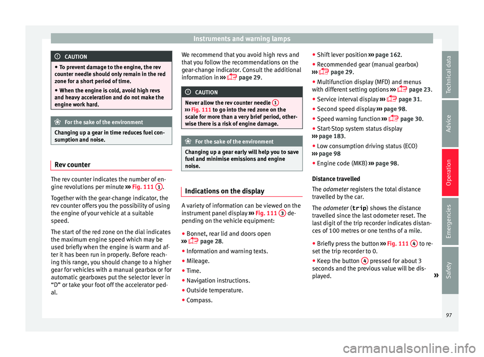
Fig. 111 1 .
T og
ether w
ith the gear-change indicator, the
rev counter offers you the possibility of using
the engine of your vehicle at a suitable
speed.
The start of the red zone on the dial indicates
the maximum engine speed which may be
used briefly when the engine is warm and af-
ter it has been run in properly. Before reach-
ing this range, you should change to a higher
gear for vehicles with a manual gearbox or for
automatic gearboxes put the selector lever in
“D” or take your foot off the accelerator ped-
al. We recommend that you avoid high revs and
that
you follow the recommendations on the
gear-change indicator. Consult the additional
information in ›››
page 29. CAUTION
Never allow the rev counter needle 1 ›››
Fig. 111 to g o int
o the red zone on the
scale for more than a very brief period, other-
wise there is a risk of engine damage. For the sake of the environment
Changing up a gear early will help you to save
fuel and minimi
se emissions and engine
noise. Indications on the display
A variety of information can be viewed on the
in
s
trument
panel display ›››
Fig. 111 3 de-
pendin g on the
v
ehicle equipment:
● Bonnet, rear lid and doors open
›››
page 28.
● Information and warning texts.
● Mileage.
● Time.
● Navigation instructions.
● Outside temperature.
● Compass. ●
Shift l
ever position ››› page 162.
● Recommended gear (manual gearbox)
›››
page 29.
● Multifunction display (MFD) and menus
with differ
ent setting options ›››
page 23.
● Service interval display ›››
page 31.
● Second speed display ›››
page 98.
● Speed warning function ›››
page 30.
● Start-Stop system status display
›››
page 183.
● Low consumption driving status (ECO)
›››
page 98
● Engine code (MKB) ›››
page 98.
Distance travelled
The odometer registers the total distance
travelled by the car.
The odometer (trip ) shows the distance
travelled since the last odometer reset. The
last digit of the trip recorder indicates distan-
ces of 100 metres or one tenths of a mile.
● Briefly press the button ›››
Fig. 111 4 to re-
set the trip r
ec
order to 0.
● Keep the button 4 pressed for about 3
sec ond
s
and the previous value will be dis-
played. »
97
Technical data
Advice
Operation
Emergencies
Safety
Page 100 of 248
Operation
Time
● To set the time, keep the button ››
› Fig. 111
4 pressed for more than 3 seconds to select
the hour or minut e di
s
play.
● To continue setting the time, press the up-
per or lower p
art of the button 4 . Hold but-
t on do
wn t
o scroll through the numbers
quickly.
● Press the button 4 again in order to finish
settin g the time.
The time c an al
so be set on the Easy Connect
system using the button and the function
b utt
on
SETTINGS > Date and time
››› page 21.
Compass
With the ignition on and the navigation sys-
tem on, the cardinal point corresponding to
the direction of travel of the vehicle is dis-
played on the instrument panel.
Selector lever position
The selected gear is displayed on the side of
the selector lever and on the instrument pan-
el display. In positions D and S, and with the
Tiptronic, the corresponding gear is also dis-
played. Recommended gear (manual gearbox)
The r
ecommended g
ear in order to save fuel
is displayed on the instrument panel while
you are driving ›››
page 29.
Second speed display (mph or km/h)
In addition to the speedometer, the speed
can also be displayed in a different unit of
measurement (in miles or in km per hour).
This option cannot be deactivated in models
destined for countries in which the second
speed must always be visible.
The second speed display can be adjusted in
the Easy Connect system by means of the button and the function button SETTINGS >
Units › ›
›
page 21.
Speed warning
When the speed setting is exceeded, this will
be indicated on the instrument panel display.
This is very useful, for example when using
winter tyres that are not designed for driving
at the maximum speed of the vehicle
››› page 30.
The speed warning settings can be adjusted
in the Easy Connect system by means of the button and the function button SET-
TINGS > Driver Assistance
› ›
›
page 21. Start-Stop operating display
Updat
ed information relating to the status is
displayed on the instrument panel
››› page 183.
Low consumption driving status (ECO)*
Depending on the equipment, when driving,
the “ECO ” display appears on the instrument
panel when the vehicle is in low consump-
tion status.
Identifying letters on engine (MKB)
Hold the button ››› Fig. 111 4 down for more
th an 15 sec
ond
s to display the identifying
letters of the vehicle engine (MKB). To do
this, the ignition must be switched on and
the engine switched off. WARNING
Observe the safety warnings ›››
in Control
and warnin g l
amps on page 101. WARNING
Even though outside temperatures are above
freez in
g, some roads and bridges may be icy.
● At outside temperatures above +4°C
(+39°F), even when the “ice c
rystal” symbol
is not visible, there may still be patches of ice
on the road.
● The outside temperature sensor takes a
guideline meas
urement.98
Page 112 of 248
Operation
WARNING
● Never l e
ave the key inside whenever you
leave the vehicle - even if only for a moment.
This is particularly important if children are
to remain in the vehicle. Children might start
the engine or some other electrical compo-
nent, e.g. electric windows. Risk of injury!
● Wait until the vehicle has completely stop-
ped before t
aking the key out of the ignition.
Otherwise the steering wheel may lock sud-
denly. Risk of accident! CAUTION
● Eac h k
ey contains electronic components
and must, therefore, be protected from damp-
ness and strong vibrations.
● Keep the grooves in the key shaft clean.
Any dir
t (fibre from clothing, dust, etc.) has a
negative impact on locks, ignition, etc. Note
Should a key be lost, request a duplicate key
from an Authori sed S
EAT dealer. Replacing the battery in the remote
c
ontr
o
l key Fig. 120
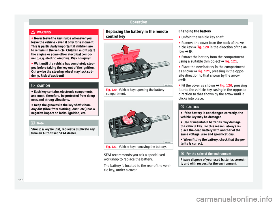
Vehicle key: opening the battery
c omp
ar
tment. Fig. 121
Vehicle key: removing the battery. SEAT recommends you ask a specialised
w
ork
shop t
o replace the battery.
The battery is located to the rear of the vehi-
cle key, under a cover. Changing the battery
● Unfold the vehicle key shaft.
● Remove the cover from the back of the ve-
hicle k
ey ››› Fig. 120 in the direction of the ar-
row ››› .
● Extract the battery from the compartment
u s
in
g a suitable thin object ››› Fig. 121.
● Place the new battery in the compartment
as sho
wn ››› Fig. 121, pressing in the oppo-
site direction to that shown by the arrow
››› .
● Fit the cover as shown ››
›
Fig. 120 , pressing
it onto the vehicle key casing in the opposite
direction to that shown by the arrow until it
clicks into place. CAUTION
● If the b att
ery is not changed correctly, the
vehicle key may be damaged.
● Use of unsuitable batteries may damage
the vehic
le key. For this reason, always re-
place the dead battery with another of the
same voltage, size and specifications.
● When fitting the battery, check that the po-
larity i
s correct. For the sake of the environment
Please dispose of your used batteries correct-
ly and w ith r
espect for the environment.110
Page 114 of 248
Operation
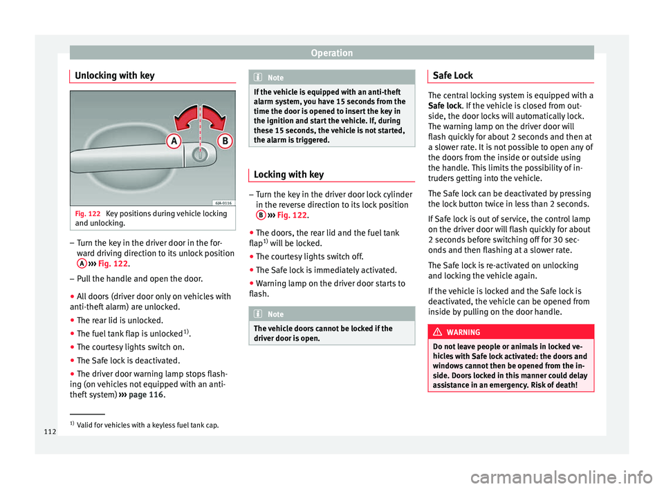
Unlocking with key Fig. 122
Key positions during vehicle locking
and u n
loc
king. –
Turn the key in the driver door in the for-
war
d driv
ing direction to its unlock position
A
› ›
›
Fig. 122.
– Pull the handle and open the door.
● All doors (driver door only on vehicles with
anti-theft al
arm) are unlocked.
● The rear lid is unlocked.
● The fuel tank flap is unlocked 1)
.
● The courtesy lights switch on.
● The Safe lock is deactivated.
● The driver door warning lamp stops flash-
ing (on v
ehicles not equipped with an anti-
theft system) ›››
page 116. Note
If the vehicle is equipped with an anti-theft
al arm sy
stem, you have 15 seconds from the
time the door is opened to insert the key in
the ignition and start the vehicle. If, during
these 15 seconds, the vehicle is not started,
the alarm is triggered. Locking with key
–
Turn the key in the driver door lock cylinder
in the rev er
se direction to its lock position
B
› ›
›
Fig. 122.
● The doors, the rear lid and the fuel tank
flap 1)
wi
ll be locked.
● The courtesy lights switch off.
● The Safe lock is immediately activated.
● Warning lamp on the driver door starts to
flash. Note
The vehicle doors cannot be locked if the
driver door i s
open. Safe Lock
The central locking system is equipped with a
Safe loc
k
. If the vehicle is closed from out-
side, the door locks will automatically lock.
The warning lamp on the driver door will
flash quickly for about 2 seconds and then at
a slower rate. It is not possible to open any of
the doors from the inside or outside using
the handle. This limits the possibility of in-
truders getting into the vehicle.
The Safe lock can be deactivated by pressing
the lock button twice in less than 2 seconds.
If Safe lock is out of service, the control lamp
on the driver door will flash quickly for about
2 seconds before switching off for 30 sec-
onds and then flashing at a slower rate.
The Safe lock is re-activated on unlocking
and locking the vehicle again.
If the vehicle is locked and the Safe lock is
deactivated, the vehicle can be opened from
inside by pulling on the door handle. WARNING
Do not leave people or animals in locked ve-
hicl e
s with Safe lock activated: the doors and
windows cannot then be opened from the in-
side. Doors locked in this manner could delay
assistance in an emergency. Risk of death! 1)
Valid for vehicles with a keyless fuel tank cap.
112
Page 131 of 248
Lights and visibility
the ignition. If you switch on the windscreen
wiper
s
when the wiper blades are frozen to
the glass, this could damage both the wiper
blades and the wiper motor.
● If the ignition is switched off when the
winds
creen wipers are on, they will start op-
erating in the same mode when the ignition
is switched back on. The wiper blades may be
frozen to the glass at low temperatures when
the ignition is switched off.
● Carefully separate the frozen wipers from
the winds
creen or rear window.
● Remove snow and ice from the wipers be-
fore s
tarting your journey.
● Careless handling could lead to the wiper
arms dam
aging the windscreen.
● For safety reasons, the wiper blades should
be chan
ged once or twice a year. They can be
purchased at a SEAT Authorised Service.
● The ignition cannot be switched on while
the winds
creen wiper arms are in a raised po-
sition. Otherwise, the windscreen wipers
would return to their original position and
could damage the paintwork on the bonnet. Note
Keep the wipers clean. The wipers can be
soil ed w
ith remains of wax solutions from car
washes ››› page 196.
● On vehicles equipped with windscreen
washer j
ets, these are heated once the en-
gine is running. Operating windscreen wipers and
w
a
sher
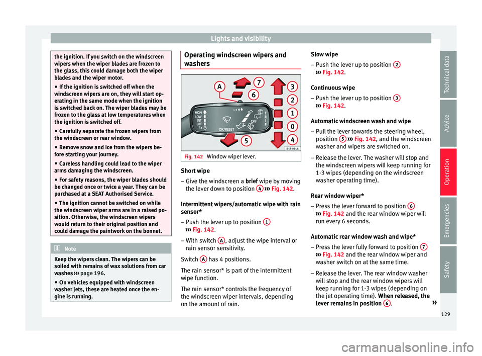
s Fig. 142
Window wiper lever. Short wipe
– Give the windscreen a brief w ipe b
y
moving
the lever down to position 4
› ›
› Fig. 142 .
Intermittent wipers/automatic wipe with rain
sensor* – Push the lever up to position 1 ›››
Fig. 142.
– With switch A , adjust the wipe interval or
r ain sen
sor sen
sitivity.
Switch A has 4 positions.
The r ain sen
sor* i
s part of the intermittent
wipe function.
The rain sensor* controls the frequency of
the windscreen wiper intervals, depending
on the amount of rain. Slow wipe
–
Push the lever up to position 2 ›››
Fig. 142.
C ontinuou
s
wipe
– Push the lever up to position 3 ›››
Fig. 142.
Aut om
atic
windscreen wash and wipe
– Pull the lever towards the steering wheel,
position 5
› ››
Fig. 142
, and the w
indscreen
washer and wipers are switched on.
– Release the lever. The washer will stop and
the winds
creen wipers will keep running for
1-3 wipes (depending on the windscreen
washer operating time).
Rear window wiper*
– Press the lever forward to position 6 ›››
Fig. 142 and the re ar w
indow wiper will
run every 6 seconds.
Automatic rear window wash and wipe* – Press the lever fully forward to position 7 ›››
Fig. 142 and the re ar w
indow wiper and
washer switch on at the same time.
– Release the lever. The rear window washer
wi l
l stop and the rear window wipers will
keep running for 1-3 wipes (depending on
the jet operating time). When released, the
lever remains in position 6 .
»
129
Technical data
Advice
Operation
Emergencies
Safety
Page 154 of 248
Operation
In the event of prolonged, irregular distribu-
tion of the air flo
w fr
om the outlets (particu-
larly the footwells) and significant differen-
ces in temperature, e.g. on leaving the vehi-
cle, sensitive people may catch cold.
Air recirculation Air recirculation prevents unpleasant smells,
e.g. when p
a
ssing through a tunnel or in
queuing traffic, from entering the interior.
Switching on air recirculation mode
● Press the button 17
› ›
› Fig. 172
and the
symbol is displayed on the screen.
Switching off air recirculation mode
● Press the button 17
› ›
› Fig. 172
and the
symbol disappears from the screen. WARNING
Read and observe the safety warnings ›››
in
Genera l
notes on page 146. Note
If air recirculation mode remains on for 15 mi-
nute s, the
symbol will start to flash on
the screen to indicate prolonged air recircula-
tion. If air recirculation is not switched off,
the symbol will continue to flash for about 5
minutes. Blower selection
Climatronic automatically regulates blower
speed ac
c
ording to the interior temperature.
It is possible, however, to set the blower
speed to suit requirements.
● Turn control 10
››› Fig. 172 c
ounter-clock-
wise (to lower the speed) or clockwise (to in-
crease the speed).
Climatronic will switch off when the blower
switches off. WARNING
Read and observe the safety warnings ›››
in
Genera l
notes on page 146. Windscreen defrost
Switching on windscreen defrosting
●
Press the button
12
› ›
›
Fig. 172.
Switching off windscreen defrosting
● Press the button 12
› ›
›
Fig. 172 sev-
eral times or press the button.
The temperature is regulated automatically.
The air output is increased from vents 1
››› page 147 and 2. Driving
St ar
tin
g and stopping the en-
gine
Introduction Read the additional information carefully
›› ›
page 18 WARNING
● When mov in
g with the engine switched off,
the ignition key must always remain in posi-
tion 2
››› Fig. 173 ›
›› page 154 (ignition on).
The control lamps will light up in this posi-
tion. Otherwise, the steering lock could en-
gage suddenly. Risk of accident!
● Do not remove the key from the ignition un-
til the
vehicle has come to a standstill and is
secure (e.g. the handbrake is engaged). Oth-
erwise, the steering lock could suddenly en-
gage. Risk of accident!
● Always take the ignition key with you when
you le
ave the vehicle. This is particularly im-
portant if you leave children in the vehicle.
Children could, for example, start the engine
with the subsequent risk of accident.
● Never leave the engine running in unventi-
lated or c
losed rooms. The exhaust gases
contain carbon monoxide, an odourless and
colourless poisonous gas. Risk of fatal acci-
dents! Carbon monoxide can cause people to
lose consciousness and can cause death. 152
Page 155 of 248
Driving
●
Never l e
ave the vehicle unattended if the
engine is running.
● Never switch the engine off until the vehi-
cle h
as come to a complete stop. Risk of acci-
dent! CAUTION
● Turnin g the s
teering wheel fully in either
direction when the vehicle is stationary and
the engine is in gear puts the power steering
under great stress. This could lead to noise.
Never leave the steering wheel turned fully in
either direction for more than 15 seconds.
Risk of damage to the power steering system!
● The starter motor may only be used (key
position 3
››› Fig. 173 ›
›› page 154 in the ig-
nition) if the engine is off. Using the starter
motor when the engine is running could dam-
age it.
● Immediately release the ignition key when
the engine st
arts, otherwise damage could be
caused to the starter motor.
● When the engine is cold, you should avoid
high engine speed
s, driving at full throttle
and over-loading the engine before it reaches
operating temperature. Risk of engine dam-
age!
● Do not tow-start the engine. Risk of engine
damag
e! In vehicles with a catalytic convert-
er, fuel that has not been burned could reach
the catalytic converter and catch fire in it.
This would lead to a fault in the catalytic con-
verter. You may use the battery from another vehicle to help you start your engine
›› ›
page 52.
● After prolonged and demanding operation
of the engine, when the j
ourney has ended,
do not stop the engine immediately. Let the
engine run at idle for about one more minute.
This will stop the engine from overheating. For the sake of the environment
Do not warm up the engine when the vehicle
i s s
tationary. If possible, move off immediate-
ly after starting the engine. This will help the
engine reach operating temperature more
quickly, reducing the quantity of emissions. Note
● The engine c an on
ly be started with the
original SEAT key.
● Loud running noises may be heard briefly
after c
old-starting the engine. This is normal
and is no cause for concern.
● After the engine has been stopped and the
ignition switc
hed off, the radiator fan may
continue running for around 10 minutes.
● If the engine still does not start after a sec-
ond attempt, the fuel
pump fuse might have
blown. Check it and replace if necessary
››› page 81 or contact your Specialised Serv-
ice.
● You should always engage the steering lock
when you e
xit the vehicle. This will hinder
any attempts at theft. Power steering
The power steering allows you to turn the
st
eerin
g wheel more easily.
If the power steering fails or the engine is off
(towing), it is still possible to turn the vehi-
cle's steering wheel fully. However, you need
more strength to steer the vehicle.
Driver control lamps and warnings (in red) Faulty steering! To
park the vehicle
If the warning lamp remains on and the driver
indication appears, the power steering could
be faulty.
Do not continue driving. Seek specialist as-
sistance. (in yellow) Steering: System
fault! You may continue driving.
If the warning lamp comes on, the steering
could react with more difficultly or more sen-
sitivity than normal. In addition, when driving
in a straight line the steering wheel may be
off-centre.
Drive slowly to a specialised workshop and
have the fault repaired. (in yellow) Steering lock:
fault! Go to an Official Service
The electronic steering lock is malfunction-
ing. »
153
Technical data
Advice
Operation
Emergencies
Safety
Page 156 of 248
Operation
Go to a specialised workshop as soon as
po s
s
ible and have the fault repaired. WARNING
Take it immediately to a specialised work-
shop and hav e the f
ault repaired: risk of acci-
dent! Note
If the lamp (in red) or (in
yellow) lights
up briefly, you may continue driving. Start-up lock security system (immo-
b
i
li
ser) There is an electronic chip in the key. The
el
ectr
onic
immobiliser is deactivated when
the key is inserted into the ignition. The elec-
tronic immobiliser is automatically activated
when the key is removed from the ignition.
The engine will not start if an unauthorised
key is used.
The informative display indicates:
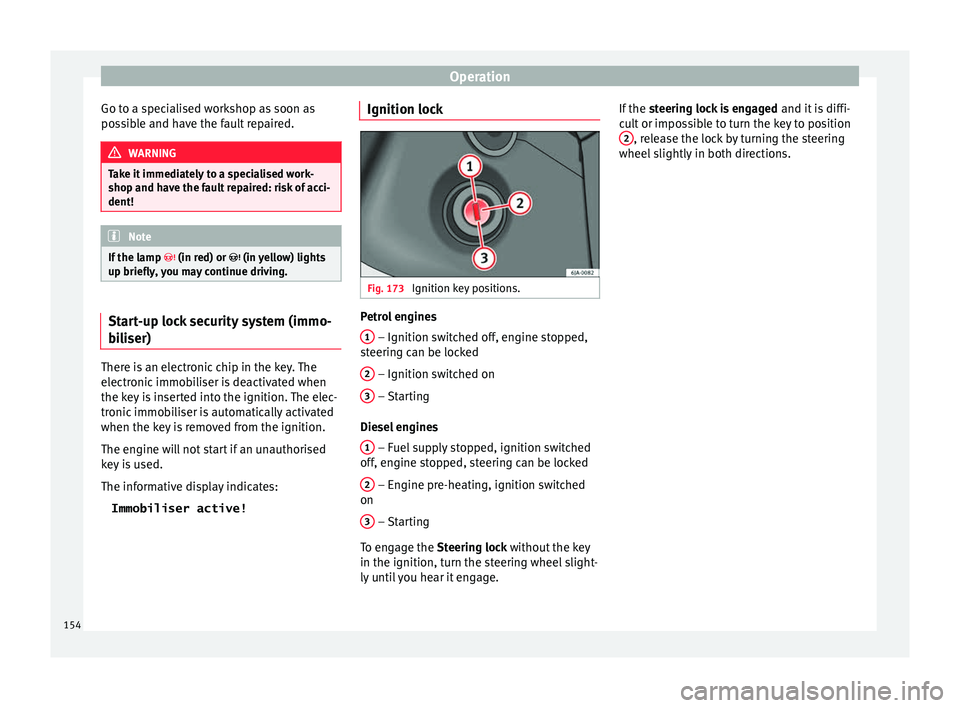
Immobiliser active! Ignition lock
Fig. 173
Ignition key positions. Petrol engines
1 – Ignition switched off, engine stopped,
s t
eerin
g can be locked
2 – Ignition switched on
3 – Starting
Die sel
en
gines
1 – Fuel supply stopped, ignition switched
off , en
gine s
topped, steering can be locked
2 – Engine pre-heating, ignition switched
on
3 – Starting
T o en
g
age the Steering lock without the key
in the ignition, turn the steering wheel slight-
ly until you hear it engage. If the
steering lock is engaged and it i
s diffi-
cult or impossible to turn the key to position 2 , release the lock by turning the steering
wheel s
lightly
in both directions.
154
Page 157 of 248
Driving
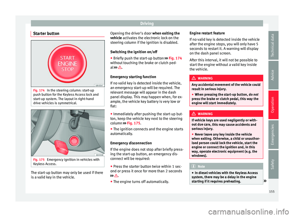
Starter button Fig. 174
In the steering column: start-up
p u
sh b
utton for the Keyless Access lock and
start-up system. The layout in right-hand
drive vehicles is symmetrical. Fig. 175
Emergency ignition in vehicles with
K eyl
e
ss Access. The start-up button may only be used if there
i
s a
valid key in the vehicle. Opening the driver's door
when exitin
g the
vehicle activates the electronic lock on the
steering column if the ignition is disabled.
Switching the ignition on/off
● Briefly push the start-up button ›››
Fig. 174
without touching the brake or clutch ped-
al ››› .
Emer g
ency
starting function
If no valid key is detected inside the vehicle,
an emergency start-up will be required. The
relevant message will appear in the dash
panel display. This may happen when, for ex-
ample, the vehicle key battery is very low or
flat:
● Immediately after pushing the start-up but-
ton, keep the
vehicle key next to the steering
column ››› Fig. 175.
● The ignition connects and the engine starts
automatic
ally.
Emergency disconnection
If the engine does not stop after briefly press-
ing the start-up button, an emergency dis-
connect will be required:
● Press the starter button twice within 1 sec-
ond or pres
s it once for more than 2 seconds
››› .
● The engine turns off automatically. Engine restart feature
If
no
v
alid key is detected inside the vehicle
after the engine stops, you will only have 5
seconds to restart it. A warning will display
on the dash panel screen.
After this interval, it will not be possible to
start the engine without a valid key inside
the vehicle. WARNING
Any accidental movement of the vehicle could
re s
ult in serious injury.
● When pressing the start-up button, do not
pre
ss the brake or clutch pedal, this way the
engine will start immediately. WARNING
If vehicle keys are used negligently or with-
out due c ar
e, this may cause accidents and
serious injury.
● Never leave any key inside the vehicle
when exitin
g. Otherwise, a child or unauthor-
ised person could lock the vehicle, start the
engine or connect the ignition and, in this
way, operate electronic equipment (e.g. the
windows). Note
● In diesel
vehicles with the Keyless Access
system, there may be a delay in the engine
starting if it requires preheating. » 155
Technical data
Advice
Operation
Emergencies
Safety
Page 158 of 248

Operation
●
If the v
ehicle is stationary for a long time
with the ignition on, the vehicle battery
might be discharged and it might not be pos-
sible to start the engine. Starting the engine
Vehicles with a
diesel en
gine are equipped
with a glow plug system. When you switch on
the ignition, the glow plug warning lamp
will light up. The engine can be started
straight away when the lamp switches off.
Do not connect electrical appliances during
preheating so as not the drain the vehicle
battery unnecessarily.
Starting the engine
● Move the gearbox lever into neutral or
mov e the sel
ector lever to position P or N and
pull firmly on the handbrake.
● Press the clutch pedal all the way down
and star
t the engine 3
› ›
› Fig. 173
›
›› page 154, without pressing the accelera-
tor. Keep the clutch pedal pressed down until
the engine starts.
● Release the ignition key as soon as the en-
gine star
ts. The key returns to position 2 .
● If the engine does not start after 10 sec-
ond s, t
urn the k
ey back to position 1 . Re-
pe at
the action af
ter 30 seconds.
● Release the handbrake before moving off. Switching off the engine with the key Stop the engine by turning the ignition key to
pos
ition 1
››› Fig. 173 ›
›› page 154.
Brakes and brake servo sys-
tems Introduction WARNING
● The brak e ser
vo only works when the en-
gine is running. Braking when the engine is
switched off requires applying more strength
to the brake pedal. Risk of accident!
● Press down on the clutch pedal when stop-
ping and brak
ing with a manual gearbox, pet-
rol engine vehicle at low speed. Otherwise,
the brake servo might not work properly. Risk
of accident!
● In the event of damage to the standard
front s
poiler or where a different front spoil-
er, wheel trims, etc. are subsequently fitted,
make sure the air vent to the brakes on the
front wheels is not blocked. Otherwise, brak-
ing operations may be impaired. Risk of acci-
dent!
● Always fully release the handbrake. If it is
only p
artially released, this will cause over-
heating of the rear brakes, which can impair
the function of the brake system. Risk of acci-
dent! ●
Never l e
ave children unsupervised in the
vehicle. They could release the handbrake or
move the gear lever. The vehicle could start
moving. Risk of accident!
● Insufficient fuel can cause the engine to run
irregu
larly or to switch off. Brake assist sys-
tems could be impaired. Risk of accident!
● Always adjust your driving style to suit visi-
bility
, the weather and road and traffic condi-
tions. The best vehicle safety offered by
brake assist systems must never encourage
you to run greater risks. Risk of accident! CAUTION
● Ob ser
ve the information concerning new
brake pads ››› page 165.
● Where braking is not necessary, do not
wear do
wn the brake pads by pressing down
gently on the brake pedal. This causes the
brakes to overheat, increasing their wear and
increasing braking distances.
● To ensure the brake assist systems work
properly, a
ll wheels must be fitted with tyres
approved by the manufacturer. Note
● If y
ou brake suddenly and the brake system
control unit regards the situation as hazard-
ous for the drivers behind you, the brake
lights will begin to flash automatically. After
reducing speed to approximately 10 km/h (6
mph) or stopping the vehicle, the brake lights
will stop flashing and the hazard warning 156