trailer Seat Toledo 2017 Owner's manual
[x] Cancel search | Manufacturer: SEAT, Model Year: 2017, Model line: Toledo, Model: Seat Toledo 2017Pages: 248, PDF Size: 5.86 MB
Page 6 of 248
Table of Contents
Engine management and emission control sys-
t em
. . . . . . . . . . . . . . . . . . . . . . . . . . . . . . . . . . . 167
Driv
ing tips . . . . . . . . . . . . . . . . . . . . . . . . . . . . . 169
Driver assistance systems . . . . . . . . . . . . . . . . . 170
Parking aid . . . . . . . . . . . . . . . . . . . . . . . . . . . . . 170
Rear Assist “Rear View Camera”* . . . . . . . . . . . 175
Cruise speed (Cruise Control)* . . . . . . . . . . . . . 178
Emergency brake assist system (Front As-
sis
t)* . . . . . . . . . . . . . . . . . . . . . . . . . . . . . . . . . . 179
Start-Stop System* . . . . . . . . . . . . . . . . . . . . . . . 183
Fatigue detection (break recommendation)* . . 185
Towing bracket device . . . . . . . . . . . . . . . . . . . . 186
Driving with a trailer . . . . . . . . . . . . . . . . . . . . . . 186
Towing bracket device . . . . . . . . . . . . . . . . . . . . 188
Advice . . . . . . . . . . . . . . . . . . . . . . . . . . . . . . . . 194
Care and maintenance . . . . . . . . . . . . . . . . . . . . 194
Accessories and modifications to the vehi-
cle
. . . . . . . . . . . . . . . . . . . . . . . . . . . . . . . . . . . . 194
Care and cleaning . . . . . . . . . . . . . . . . . . . . . . . 195
Checking and refilling levels . . . . . . . . . . . . . . . 201
Fuel . . . . . . . . . . . . . . . . . . . . . . . . . . . . . . . . . . . 201
Engine compartment . . . . . . . . . . . . . . . . . . . . . 204
Engine oil . . . . . . . . . . . . . . . . . . . . . . . . . . . . . . 207
Coolant . . . . . . . . . . . . . . . . . . . . . . . . . . . . . . . . 210
Brake fluid . . . . . . . . . . . . . . . . . . . . . . . . . . . . . 211
Window washer system . . . . . . . . . . . . . . . . . . . 212
Battery . . . . . . . . . . . . . . . . . . . . . . . . . . . . . . . . . 213
Wheels and tyres . . . . . . . . . . . . . . . . . . . . . . . . 217
Tyres . . . . . . . . . . . . . . . . . . . . . . . . . . . . . . . . . . 217
Spare wheel . . . . . . . . . . . . . . . . . . . . . . . . . . . . 220
Tyre monitoring systems . . . . . . . . . . . . . . . . . . 221
Winter service . . . . . . . . . . . . . . . . . . . . . . . . . . . 222
Technical data . . . . . . . . . . . . . . . . . . . . . . . . 223
Technical specifications . . . . . . . . . . . . . . . . . . 223
Important information . . . . . . . . . . . . . . . . . . . . 223
Information on fuel consumption . . . . . . . . . . . 224 Driving with a trailer . . . . . . . . . . . . . . . . . . . . . . 225
Wheels . . . . . . . . . . . . . . . . . . . . . . . . . . . . . . . . 226
Engine data . . . . . . . . . . . . . . . . . . . . . . . . . . . . . 227
Dimensions . . . . . . . . . . . . . . . . . . . . . . . . . . . . . 233
Index . . . . . . . . . . . . . . . . . . . . . . . . . . . . . . . . . 235
4
Page 31 of 248
The essentials
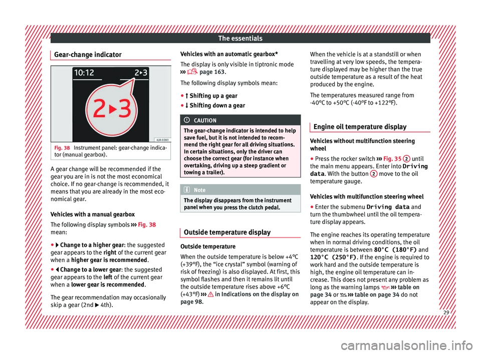
Gear-change indicator Fig. 38
Instrument panel: gear-change indica-
t or (m
anual
gearbox). A gear change will be recommended if the
g
e
ar
you are in is not the most economical
choice. If no gear-change is recommended, it
means that you are already in the most eco-
nomical gear.
Vehicles with a manual gearbox
The following display symbols ›››
Fig. 38
mean:
● Chan ge to a higher gear: the suggested
g
ear appears to the right of the current gear
when a higher gear is recommended .
● Change to a lower gear: the suggested
g
ear appears to the left of the current gear
when a lower gear is recommended .
The gear recommendation may occasionally
skip a gear (2nd 4th). Vehicles with an automatic gearbox*
The dis
p
lay is only visible in tiptronic mode
››› page 163.
The following display symbols mean:
● Shiftin g up a gear
●
Shifting down a gear CAUTION
The gear-change indicator is intended to help
sav e f
uel, but it is not intended to recom-
mend the right gear for all driving situations.
In certain situations, only the driver can
choose the correct gear (for instance when
overtaking, driving up a steep gradient or
towing a trailer). Note
The display disappears from the instrument
panel when
you press the clutch pedal. Outside temperature display
Outside temperature
When the outs
ide t
emper
ature is below +4°C
(+39°F), the “ice crystal” symbol (warning of
risk of freezing) is also displayed. At first, this
symbol flashes and then it remains lit until
the outside temperature rises above +6°C
(+43°F) ››› in Indications on the display on
p ag
e 98
. When the vehicle is at a standstill or when
travel
ling at very low speeds, the tempera-
ture displayed may be higher than the true
outside temperature as a result of the heat
produced by the engine.
The temperatures measured range from
-40°C to +50°C (-40°F to +122°F).
Engine oil temperature display Vehicles without multifunction steering
wheel
● Press the rocker switch ›
››
Fig. 35 2 until
the m ain menu ap
pe
ars. Enter into Driving
data . With the button 2 move to the oil
t emper
at
ure gauge.
Vehicles with multifunction steering wheel
● Enter the submenu Driving data and
turn the thumbwheel
until the oil tempera-
ture display appears.
The engine reaches its operating temperature
when in normal driving conditions, the oil
temperature is between 80°C (180°F) and
120°C (250°F) . If the engine is required to
work hard and the outside temperature is
high, the engine oil temperature can in-
crease. This does not present any problem as
long as the warning lamps ›››
table on
page 34 or ››› table on page 34 do not
appear on the display. 29
Page 36 of 248
The essentials
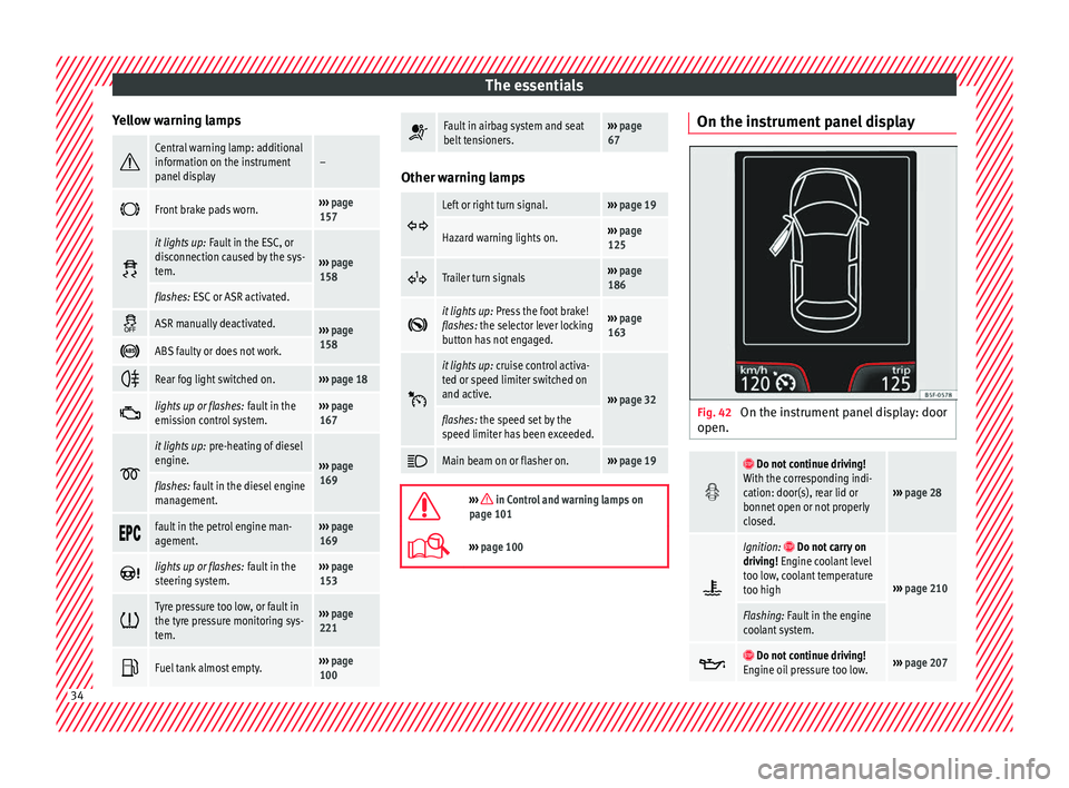
Yellow warning lamps Central warning lamp: additional
information on the instrument
panel display–
Front brake pads worn.›››
page
157
it lights up:
Fault in the ESC, or
disconnection caused by the sys-
tem.
››› page
158
flashes: ESC or ASR activated.
ASR manually deactivated.›››
page
158
ABS faulty or does not work.
Rear fog light switched on.›››
page 18
lights up or flashes:
fault in the
emission control system.››› page
167
it lights up:
pre-heating of diesel
engine.
››› page
169
flashes: fault in the diesel engine
management.
fault in the petrol engine man-
agement.›››
page
169
lights up or flashes:
fault in the
steering system.››› page
153
Tyre pressure too low, or fault in
the tyre pressure monitoring sys-
tem.›››
page
221
Fuel tank almost empty.›››
page
100
Fault in airbag system and seat
belt tensioners.›››
page
67 Other warning lamps
Left or right turn signal.›››
page 19
Hazard warning lights on.››› page
125
Trailer turn signals›››
page
186
it lights up:
Press the foot brake!
flashes: the selector lever locking
button has not engaged.››› page
163
it lights up:
cruise control activa-
ted or speed limiter switched on
and active.
››› page 32
flashes: the speed set by the
speed limiter has been exceeded.
Main beam on or flasher on.›››
page 19
››› in Control and warning lamps on
page 101
››› page 100 On the instrument panel display
Fig. 42
On the instrument panel display: door
open.
Do not continue driving!
With the corresponding indi-
cation: door(s), rear lid or
bonnet open or not properly
closed.
››› page 28
Ignition: Do not carry on
driving! Engine coolant level
too low, coolant temperature
too high
››› page 210
Flashing: Fault in the engine
coolant system.
Do not continue driving!
Engine oil pressure too low.››› page 207 34
Page 47 of 248
The essentials
To replace a fuse
● Remove the fuse.
● Replace the blown fuse by one with an
iden tic
a
l amperage rating (same colour and
markings) and identical size.
● Replace the cover again or close the fuse
box lid.
B
ulbs
Bul
bs (12 V) Full-LED headlights are designed to last the
lif
etime of
the c
ar and cannot be replaced. If
the headlight becomes damaged, go to a
specialised workshop.
Below, the light source used for all functions
is broken down.
Halogen headlights.Type
Daytime running light/side
lightP21W SLL
Dipped beam headlightsH7 LL
Main beam headlightsH7 LL
Turn signalPY21W
Full-LED main headlightsType
No bulbs may be replaced. All functions are with LEDs
Front fog lightType
Fog/cornering lights*H8
Rear bulb lightType
Brake light/tail lightP21/5W
Side lightsP21/5W (side panel)
R5W (rear lid)
Turn signalPY21W
Retro fog lightP21W
Reverse lightsP21W
LED rear lightsType
Turn signalPY21W
Retro fog lightP21W
Reverse lightsP21W
The remaining functions work with LEDs
›››
page 84 Action in the event of a punc-
t
ur
e
Wh
at to do first ●
Park the vehicle on a horizontal surface
and in a saf e p
lace as far away from traffic as
possible.
● Apply the handbrake.
● Switch on the hazard warning lights.
● Manual gearbox: select the 1s
t gear.
● Automatic gearbox: Move the sel
ector lever
to position P.
● If you are towing a trailer, unhitch it from
your v
ehicle.
● Have the vehicle tool kit* ›››
page 76
and the spare wheel ›››
page 220 ready.
● Observe the applicable legislation for each
countr
y (reflective vest, warning triangles,
etc.).
● All occupants should leave the vehicle and
wait in a s
afe place (for instance behind the
roadside crash barrier). WARNING
● Alw a
ys observe the above steps and pro-
tect yourself and other road users.
● If you change the wheel on a slope, block
the wheel on the oppo
site side of the car with
a stone or similar to prevent the vehicle from
moving. 45
Page 82 of 248
Emergencies
CAUTION
● Do not t o
w-start the engine. Risk of engine
damage! In vehicles with a catalytic convert-
er, fuel that has not been burned could reach
the catalytic converter and catch fire in it.
This could damage and destroy the catalytic
converter. You may use the battery from an-
other vehicle to help you start your engine
››› page 53.
● If, due to a fault, there is no oil in the gear-
box, the car m
ay only be towed with the driv-
en wheels lifted clear of the road and trans-
ported on a special vehicle transporter or
trailer.
● If normal towing is not possible or if the ve-
hicle i
s to be towed for further than 50 km,
the vehicle must be transported on a special
vehicle transporter or trailer.
● The towrope should be slightly elastic to
reduce the lo
ad on both vehicles during tow-
ing. It is advisable to use a towrope made of
synthetic fibre or similar material only.
● Do not pull too hard with the towing vehicle
and alwa
ys take care to avoid jerking the tow-
rope. When towing on a loose surface there is
always a risk of overloading and damaging
the anchorage points.
● Attach the towrope or towbar only to the
towline anc
horages or to the removable tow-
ing bracket ››› page 186, or ››› page 80. Note
● We r ec
ommend you use the towrope or tow-
bar available in the SEAT Original Accessories
programme from authorised SEAT dealers.
● Towing a vehicle requires a certain degree
of practic
al skill. Both drivers should be fa-
miliar with the technique required for towing.
Inexperienced drivers should not attempt to
tow away another vehicle or to have their ve-
hicle towed.
● Note the legal regulations concerning tow-
ing, par
ticularly those regarding the signal-
ling of the towed and towing vehicle.
● The towrope must not be twisted, as under
cert
ain circumstances this could unscrew the
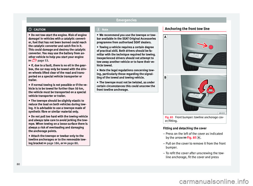
front towline anchorage. Anchoring the front tow line
Fig. 85
Front bumper: towline anchorage cov-
er/fittin g. Fitting and detaching the cover
– Press on the left of the cover as indicated
by
the arr
ow ››› Fig. 85 .
– Pull on the cover to remove it from the front
bumper.
– T
o refit the cover after unscrewing the tow-
line anchorag
e, fit the cover and press
80
Page 84 of 248
Emergencies
●
Prot ect
the fuse boxes when open to pre-
vent the entry of dust or humidity as they can
damage the electrical system.
● Always carefully remove the fuse box cov-
ers and r
efit them correctly to avoid problems
with your vehicle. Note
● One c omponent m
ay have more than one
fuse.
● Several components may run on a single
fuse.
● In the
vehicle, there are more fuses than
those indicat
ed in this chapter. These should
only be changed by a specialised workshop.
● Positions not containing a fuse do not ap-
pear in the fo
llowing tables.
● Some of the equipment listed in the tables
below pert
ain only to certain versions of the
model or are optional extras.
● Please note that the above lists, while cor-
rect at
the time of printing, are subject to
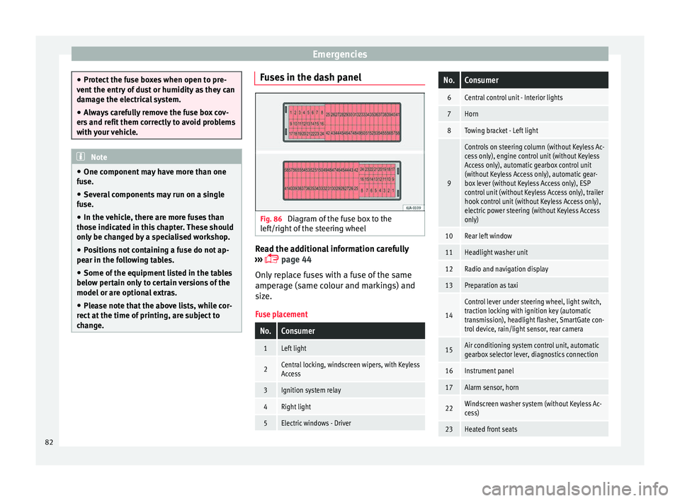
change. Fuses in the dash panel
Fig. 86
Diagram of the fuse box to the
l ef
t/right
of the steering wheel Read the additional information carefully
› ›
›
page 44
Only replace fuses with a fuse of the same
amperage (same colour and markings) and
size.
Fuse placement
No.Consumer
1Left light
2Central locking, windscreen wipers, with Keyless
Access
3Ignition system relay
4Right light
5Electric windows - Driver
No.Consumer
6Central control unit - Interior lights
7Horn
8Towing bracket - Left light
9
Controls on steering column (without Keyless Ac-
cess only), engine control unit (without Keyless
Access only), automatic gearbox control unit
(without Keyless Access only), automatic gear-
box lever (without Keyless Access only), ESP
control unit (without Keyless Access only), trailer
hook control unit (without Keyless Access only),
electric power steering (without Keyless Access
only)
10Rear left window
11Headlight washer unit
12Radio and navigation display
13Preparation as taxi
14
Control lever under steering wheel, light switch,
traction locking with ignition key (automatic
transmission), headlight flasher, SmartGate con-
trol device, rain/light sensor, rear camera
15Air conditioning system control unit, automatic
gearbox selector lever, diagnostics connection
16Instrument panel
17Alarm sensor, horn
22Windscreen washer system (without Keyless Ac-
cess)
23Heated front seats 82
Page 127 of 248

Lights and visibility
Rear fog light Switching on the rear fog light
– First turn the light switch ››› Fig. 134
››› page 124 to position , or .
– Pull on the light switch to position 2 .
If the v
ehicle is not equipped with front fog
lights ››› page 124, the rear fog light is
switched on by turning the switch to position
or and pulling it to position 2 . This
type of sw it
ch only has one position.
The ››› page 100 warning lamp lights up on
the general instrument panel if the rear fog
lights are switched on.
If you are towing a trailer or caravan equip-
ped with a rear fog light on a vehicle with a
factory-fitted towing bracket or one installed
using parts from the original SEAT parts
catalogue, only the rear fog light on the trail-
er or caravan will light up.
Function “Coming Home”/“Leaving
Home”* This function makes it possible, under poor
v
i
s
ibility conditions, to automatically turn on
the lights for a brief period of time after the
vehicle has been parked or when approach-
ing the vehicle. The function is automatically turned on if the
fol
lowing conditions are met:
● The light switch is in position
››
› page 123.
● The visibility around the vehicle is reduced.
● The ignition is switched off.
To turn on thi
s function, switch on the head-
light flasher prior to exiting the vehicle.
The light is adjusted according to the data re-
corded by the light sensor that is installed
between the windscreen and the inside rear
view mirror.
The function automatically turns on the side
lights and headlights, the lighting for the en-
try area on the exterior mirrors and the num-
ber plate light.
“Coming Home” function
The light is automatically switched on when
the driver door is opened (for 60 seconds af-
ter the ignition is switched off).
The light is switched off when all the doors
and the rear lid are closed.
If a door or the rear lid remains open, the
light will switch off after 60 seconds.
“Leaving Home” function
The light is automatically switched on when
the vehicle is unlocked using the remote con-
trol. The light is switched off after 10 seconds or
when the vehic
le is locked.
Hazard warning lights switch Fig. 135
Instrument panel: switch for hazard
w arnin
g lights. –
Press the button ››
›
Fig. 135 to switch
the hazard warning lights on or off.
The warning lamps on the instrument panel
and the warning lamp on the switch will flash
at the same time as the turn signals when
the hazard warning lights are switched on.
The hazard warning lights also work when
the ignition is switched off.
The hazard warning lights come on automati-
cally in the event of an accident in which an
airbag is triggered. »
125
Technical data
Advice
Operation
Emergencies
Safety
Page 164 of 248
Operation
engine power. Depending on the road speed
and en gine s
peed, the aut
omatic gearbox
shifts down and the vehicle accelerates. It
only shifts up after the maximum engine
speed has been reached.
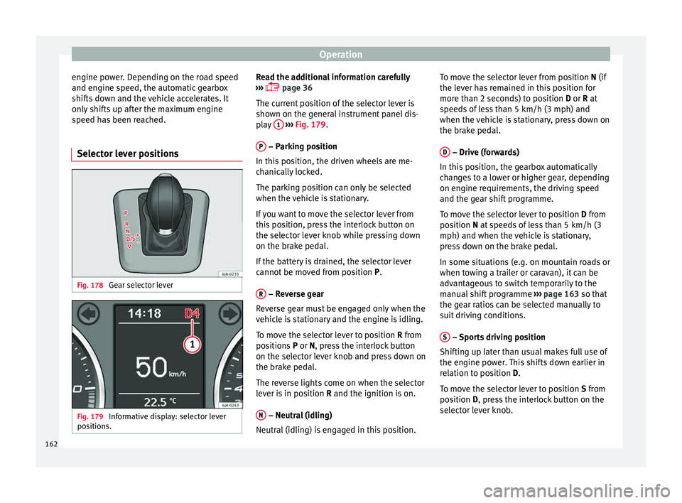
Selector lever positions Fig. 178
Gear selector lever Fig. 179
Informative display: selector lever
po sition
s. Read the additional information carefully
› ›
›
page 36
The current position of the selector lever is
shown on the general instrument panel dis-
play 1
› ››
Fig. 179
.
P – Parking position
In thi s
po
sition, the driven wheels are me-
chanically locked.
The parking position can only be selected
when the vehicle is stationary.
If you want to move the selector lever from
this position, press the interlock button on
the selector lever knob while pressing down
on the brake pedal.
If the battery is drained, the selector lever
cannot be moved from position P.
R – Reverse gear
R ev
er
se gear must be engaged only when the
vehicle is stationary and the engine is idling.
To move the selector lever to position R from
positions P or N, press the interlock button
on the selector lever knob and press down on
the brake pedal.
The reverse lights come on when the selector
lever is in position R and the ignition is on.
N – Neutral (idling)
Neutr al
(idlin
g) is engaged in this position. To move the selector lever from position N (if
the lever h
as remained in this position for
more than 2 seconds) to position D or R at
speeds of less than 5 km/h (3 mph) and
when the vehicle is stationary, press down on
the brake pedal.
D – Drive (forwards)
In thi s
po
sition, the gearbox automatically
changes to a lower or higher gear, depending
on engine requirements, the driving speed
and the gear shift programme.
To move the selector lever to position D from
position N at speeds of less than 5 km/h (3
mph) and when the vehicle is stationary,
press down on the brake pedal.
In some situations (e.g. on mountain roads or
when towing a trailer or caravan), it can be
advantageous to switch temporarily to the
manual shift programme ››› page 163 so that
the gear ratios can be selected manually to
suit driving conditions.
S – Sports driving position
Shif tin
g up l
ater than usual makes full use of
the engine power. This shifts down earlier in
relation to position D.
To move the selector lever to position S from
position D, press the interlock button on the
selector lever knob.
162
Page 167 of 248
Driving
displayed when the gearbox has cooled
ag ain.
R u
n-in and economical driving
The first
1,500 kmOver the first 1,500 kilometres the engine
mus
t
be run in.
Up to 1000 kilometres
– Do not drive at more than 3/4 of the maxi-
mum speed c orr
esponding to the engaged
gear, i.e. up to 3/4 of the maximum permit-
ted engine speed.
– Do not drive at full speed.
– Avoid high engine speeds.
– Do not tow a trailer.
From 1000 to 1500 k
ilometres (600 to 900
miles)
– Slowly increase the engine speed until
re
aching the maximum permitted speed of
the engaged gear, i.e. the maximum per-
mitted engine speed.
During its first few hours of running, the in-
ternal friction in the engine is greater than
later on, when all the moving parts have bed-
ded in. How the vehicle is driven over approx-
imately the first 1,500 kilometres (900 miles), determines the success of the proc-
ess
of running in the engine.
Even after running in, the vehicle should not
be unnecessarily driven at high engine
speeds. The maximum permitted engine
speed is marked at the start of the red zone
on the rev counter dial. The gear must be
changed up when the red area is reached in
vehicles with a manual gearbox. Extremely
high engine speeds when accelerating are
automatically limited, however the engine is
not protected against high engine speeds
produced by incorrectly changing to a lower
gear, which could cause the engine to run at
revs above the maximum permitted amount,
and consequently result in damage to the en-
gine.
Additionally, vehicles with a manual gearbox
must also bear the following in mind: do not
drive with the engine speed too low. Change
down to a lower gear when the engine no
longer runs smoothly. Observe the recom-
mendations for changing gear
››› page 29.
New tyres
New tyres must be submitted to “running in”,
given that initially their grip is not yet at the
maximum level. During the first 500 km (120
miles) drive very carefully. New brake pads
New brake p
ads do not yet provide maximum
friction capacity. First they must be “run in”.
During the first 200 km (120 miles) drive very
carefully. CAUTION
All the information for speed and engine
speed r ef
ers to an engine that operates at op-
erating temperature. Do not run the engine at
high engine speeds, neither when stopped or
while driving. For the sake of the environment
Do not drive at unnecessarily high engine
speed s; c
hanging to a higher gear sooner
contributes to saving fuel, reduces operating
noise and protects the environment. Environmental compatibility
Environmental protection is a top priority in
the de
s
ign, c
hoice of materials and manufac-
ture of your new SEAT.
Constructive measures to encourage recy-
cling
● Joints and connections designed for easy
dismantlin
g.
● Modular construction to facilitate disman-
tling. »
165
Technical data
Advice
Operation
Emergencies
Safety
Page 173 of 248
Driver assistance systems
registered. Pay special attention to children
and anima
l
s.
● Always keep visual control of the vehicle
surrou
ndings: use the mirrors for additional
help. CAUTION
Parking Aid functions may be negatively af-
f ect ed b
y different factors that may lead to
damage to the vehicle or its immediate sur-
rounds:
● Under certain circumstances, the system
does not
detect or display certain objects:
– Objects such as chains, trailer draw bars,
fences, posts and thin trees.
– Objects that are located above the sen-
sors, such as protrusions in a wall.
– Objects with certain surfaces or struc-
tures, such as wire mesh fences or pow-
der snow.
● Certain surfaces of objects and garments
do not refl
ect the ultrasound sensors' sig-
nals. The system cannot detect, at least cor-
rectly, these objects or people wearing such
clothes.
● Ultrasound sensor signals may be affected
by e
xternal sound sources. In certain circum-
stances this may prevent them from detect-
ing people or objects.
● Please note that low obstacles detected by
the syst
em may no longer be registered by
the sensors as the car moves closer, so the system will not give any further warning. In
cer
t
ain circumstances, objects such as high
kerbs that could damage the bottom of the
vehicle are not detected either.
● If the first warning from the Parking Aid is
ignored, the v
ehicle could suffer considerable
damage.
● The knocks or damage on the radiator
grill
e, bumper, wheel arch and vehicle under-
body can adjust the orientation of the sen-
sors. This can affect the parking aid function.
Have the function checked by a specialised
workshop. Note
● In cer t
ain situations, the system can give a
warning even though there is no obstacle in
the detected area, e.g:
–with rough or cobbled floors or ground
with long grass;
– with external ultrasound sources, such as
cleaning vehicles or other vehicles;
– In downpours, intense snow or dense ex-
haust gases;
– if the registration plate (front or rear) is
not properly affixed to the bumper sur-
face;
– or in locations such as the brow of a hill.
● In order to guarantee good system opera-
tion, keep the ultr
asound sensors clean, free
of snow or ice, and do not cover them with
adhesives or other objects. ●
If y
ou use high-pressure or vapour equip-
ment to clean the ultrasound sensors, apply
it directly only very briefly and always from a
distance of more than 10 cm.
● Retrofitting of accessories to the vehicle,
such a
s a bicycle rack, may interfere with the
operation of the Parking Aid.
● In order to familiarise yourself with the sys-
tem, it i
s advised that you practice parking in
an area or car park that is free from traffic.
There must be good weather and light condi-
tions.
● The volume and tone of the warnings can
be modified, in addition t
o the indications
››› page 174.
● In vehicles without a driv
er information
system, these parameters can be modified in
a SEAT Official Service or in a specialised
workshop.
● Please observe information on towing a
trail
er ››› page 175.
● The display on the Easy Connect screen
shows
a slight time delay. Rear parking aid*
The rear Parking Aid assists the driver in
p
ark
in
g by means of audible warning
sounds. »
171
Technical data
Advice
Operation
Emergencies
Safety