technical data Seat Toledo 2017 User Guide
[x] Cancel search | Manufacturer: SEAT, Model Year: 2017, Model line: Toledo, Model: Seat Toledo 2017Pages: 248, PDF Size: 5.86 MB
Page 75 of 248
Transporting children safely
Read the additional information carefully
› ›
›
page 14.
The switch disables only the front passenger
front airbag.
Switching on the airbag
– Switch the ignition off.
– Open the passenger side storage compart-
ment.
– Inser
t the key into the slot of the switch for
deactivatin
g the front passenger airbag
››› Fig. 82. About 3/4 of the key should en-
ter, as far as it will go.
– Then turn the key gently to the position.
Do not
force it if you feel resistance, and
make sure you have inserted the key fully.
– Close the passenger side storage compart-
ment.
– Check, w
ith the ignition switched on, that
the contro
l lamp does not illuminate,
with the words in the
centre of the dash panel.
Control lamp with the word
(front passenger airbag disabled)
If the front passenger front airbag is disa-
bled, after switching on the ignition, the con-
trol lamp will illuminate for several seconds,
then it will switch off for about 1 s and then
switch on again. If the control lamp is flashing, there is a fault
in the disab
ling of the airbag system ››› .
Pl e
a
se go immediately to an Official Service. WARNING
● The driver of the
vehicle is responsible for
disabling or switching on the airbag.
● Always switch off the ignition before disa-
bling the fr
ont passenger airbag! Failure to do
so could result in a fault in the airbag disa-
bling system.
● Never leave the key in the airbag disabling
switc
h as it could get damaged or enable or
disable the airbag during driving.
● If the (airbag dis
abled) control lamp
flashes, the front passenger front airbag will
not trigger in the event of an accident! Have
the system immediately checked by an Offi-
cial Service. Transporting children safely
Saf ety
f
or children
Introduction For safety reasons, as we have learned from
acc
ident
statistics, we recommend that chil-
dren under 12 years of age travel in the rear
seats. Depending on their age, height and
weight, children travelling in rear seats must
use a child seat or a seat belt. For safety rea-
sons, the child seat should be installed in the
rear seat, behind the front passenger seat or
in the centre back seat.
The physical laws involved and the forces
acting in a collision apply also to children
››› page 64. But unlike adults, children do not
have fully developed muscle and bone struc-
tures. This means that children are subject to
a greater risk of injury.
To reduce the risk of injuries, children must
always use special child restraint systems
when travelling in the vehicle.
We recommend the use of child safety prod-
ucts from the SEAT Original Accessories Pro-
gramme, which includes systems for all ages
made by “Peke” (not for all countries).
These systems have been especially de-
signed and approved, complying with the
ECE-R44. regulation. »
73
Technical data
Advice
Operation
Emergencies
Safety
Page 77 of 248
Transporting children safely
Child seats Saf ety
in
structionsRead the additional information carefully
›› ›
page 16. WARNING
● When trav el
ling, children must be secured
in the vehicle with a restraint system suitable
for age, weight and size.
● Read and always observe information and
warning
s concerning the use of child seats
››› page 74. WARNING
● The ret ainin
g rings are designed only for
use with “ISOFIX” and Top Tether* system
child seats.
● Never secure other child seats that do not
have the “ISOFIX” or T
op Tether* system, or
retaining belts or objects to the fastening
rings - this can result in potentially fatal inju-
ries to the child.
● Ensure that the child seat is secured cor-
rectly u
sing the “ISOFIX” and Top Tether* se-
curing rings. Categorisation of child seats into
gr
oup
s Use only child seats that are officially ap-
pro
v
ed and suitable for the child.
Child seats are subject to the regulation ECE-
R 44. ECE-R stands for: Economic Commis-
sion for Europe Regulation.
The child seats are grouped into 5 catego-
ries:
Group 0: Up to 10 kg (up to around 9
months)
Group 0+: Up to 13 kg (up to around 18
months)
Group 1: from 9 to 18 kg (up to approx. 4
years old)
Group 2: from 15 to 25 kg (up to approx. 7
years old)
Group 3: From 22 to 36 kg (over around 7
years old)
Child seats that have been tested and ap-
proved under the ECE R44 standard bear the
test mark on the seat (the letter E in a circle
with the test number below it).
Follow the manufacturer's instructions and
observe any statutory requirements when in-
stalling and using child seats. We recommend you to always include the
manuf
act
urer's Child Seat Instruction Manual
together with the on-board documentation.
SEAT recommends you use child seats from
the Original Accessories Catalogue . These
child seats have been designed and tested
for use in SEAT vehicles. You can find the
right child seat for your model and age group
at SEAT dealers. WARNING
Read and always observe information and
warnin g
s concerning the use of child seats
››› page 74. 75
Technical data
Advice
Operation
Emergencies
Safety
Page 79 of 248

Self-help
distance. Observe applicable local legal regu-
lation
s.
This is for your own safety and that of
other drivers.
● If you have a flat tyre, stop the vehicle as
far aw
ay as possible from moving traffic. Stop
on flat, solid ground.
● If you have to change the tyre on a gradi-
ent, block
the wheel opposite the wheel be-
ing changed by placing a stone or similar ob-
ject under it to prevent the vehicle from roll-
ing away unexpectedly.
● If the vehicle has been fitted with tyres or
allo
ys that are different to those fitted in
manufacture, the instructions ››› page 219,
New tyres or wheels must be followed.
● Always raise the vehicle with the doors
closed.
● Nev
er place parts of your body, e.g. arms
and leg
s, underneath the vehicle when it is
supported only by the jack.
● Secure the base of the jack with suitable
suppor
ts so that it cannot slip. The jack could
slide if the ground below it is soft and slip-
pery and the vehicle could slip off it. There-
fore, place the jack on a firm surface or use a
large, stable base. On a slippery surface, e.g.
tile, use a non-slip base such as a rubber
mat.
● Never start the engine when the vehicle is
jack
ed. Risk of injury.
● The jack should only be used in the correct
jack
ing points. CAUTION
● The pre s
cribed tightening torque for wheel
bolts on steel and alloy wheels is 120 Nm.
● If the anti-theft wheel bolt is overly tight-
ened, this c
ould damage the bolt and the
adapter. Note
● The set of anti-thef
t wheel bolts or the
adapter are available from authorised SEAT
dealers.
● Please observe the relevant local legal reg-
ulation
s when changing the wheel. Wheel bolts
The wheel
bolts
ar
e m
atched to the rims.
When installing different wheels, e.g. to fit
light alloy wheels or wheels with winter tyres,
it is important to use the correct wheel bolts
with the right length and correctly shaped
bolt heads. This is essential for a secure fit of
the wheels and for proper operation of the
brake system. Note
● Never gr e
ase or oil the wheel bolts!
● If the wheel bolt is very tight, it may be
poss
ible to loosen it by pushing down the
end of the box spanner carefully with your foot. Hold on to the vehicle for support and
tak
e c
are not to slip.
● If you notice that the wheel bolts are rusty
and difficult
to turn when changing a wheel,
they must be replaced before having the
tightening torque checked. Tyre repairs
TMS Anti-p
uncture kit (Tyre Mobility
System)* Read the additional information carefully
› ›
›
page 46
The Tyre Mobility System is stored in a box
under the carpet in the boot.
Using the Tyre Mobility System you can relia-
bly seal tyres damaged by foreign bodies,
provided that cuts or punctures are no larger
than approx. 4 mm in diameter. Do not re-
move the foreign bodies, e.g. bolts or nails,
from the tyre!
The tyre must be repaired immediately.
The repair made using the Tyre Mobility Sys-
tem under no circumstances replaces perma-
nent tyre repair and should only be used to
drive to the nearest official service. »
77
Technical data
Advice
Operation
Emergencies
Safety
Page 81 of 248
Self-help
Filler tube with cap
Air c ompr
e
ssor
Tube for inflating tyres
Warning provided by tyre pressure moni-
toring system (it can also be integrated in
the compressor).
Air bleed screw (in its place, the compres-
sor may have a button).
ON/OFF switch
12 volt connector
Bottle of sealant
Spare tyre valve
The valve insert remover 1 has a gap at the
lo w
er end f
or a valve insert. The valve insert
can only be screwed or unscrewed in this
way. This also applies to its replacement part 11 .
WARNING
When inflating the wheel, the air compressor
and the inflat or t
ube may become hot.
● Protect hands and skin from hot parts.
● Do not place the hot flexible inflator tube or
hot air compr
essor on flammable material.
● Allow them to cool before storing the de-
vice.
● If
it is not possible to inflate the tyre to at
lea
st 2.0 bars (29 psi / 200 kPa), the tyre is
too badly damaged. The sealant is not in a 3
4
5
6
7
8
9
10
11 good condition to seal the tyre. Do not con-
tinue drivin
g.
Seek specialist assistance. CAUTION
Switch off the air compressor after a maxi-
mum of 8 operation
al minutes to avoid over-
heating! Before switching on the air compres-
sor again, let it cool for several minutes. Check after 10 minutes of driving
Screw the inflator tube
››
›
Fig. 84 5 again
and c hec
k
the pressure on the gauge 6 .
1.3 b ar (19 p
s
i / 130 kPa) and lower:
● Stop the vehicle! The tyre c
annot be sealed
sufficiently with the tyre mobility set.
● You should obtain professional assistance
›››
.
1.4 b ar (20 p
s
i / 140 kPa) and higher:
● Set the tyre pressure to the correct value
again.
● Car
efully resume your journey until you
reac
h the nearest specialised workshop with-
out exceeding 80 km/h (50 mph).
● Have the damaged tyre replaced. WARNING
Driving with an unsealed tyre is dangerous
and can c au
se accidents and serious injury.
● Do not continue driving if the tyre pressure
is 1.3
bar (19 psi / 130 kPa) and lower.
● Seek specialist assistance. Towing the vehicle
Introduction Read the additional information carefully
› ›
›
page 51.
Vehicles with manual gearbox can be towed
using a towbar or towrope. They can also be
towed with either the front or rear wheels lif-
ted off the road.
Vehicles with automatic gearbox can be tow-
ed using a towbar or towrope. They can also
be towed with the front wheels lifted off the
road. If the vehicle is towed with the rear
wheels lifted off the road the automatic gear-
box will be damaged!
Maximum towing speed is 50 km/h (31
mph). »
79
Technical data
Advice
Operation
Emergencies
Safety
Page 83 of 248
Fuses and bulbs
down on its right-hand side. The cover
mu s
t
be securely engaged.
Fitting and detaching the towline anchorage
– Screw in the towline anchorage anti-clock-
wise b
y hand as far as it will go ››› Fig. 85
.
To tighten the towline anchorage, we recom-
mend using the box spanner, the towing eye
from another vehicle or a similar object that
can be inserted through the anchorage.
– Unscrew the towline anchorage by turning
it cloc
kwise. CAUTION
The towline anchorage must be screwed in as
far a s
it will go. Otherwise there is a risk of
the screw connection shearing off during
towing or tow-starting! Fuses and bulbs
F u
se
s
Introduction Due to the constant updating of vehicles,
fu
se a
ssignments based on equipment and
the use of the same fuse for various electrical
components, it is not possible to provide an
up-to-date summary of the fuse positions for
the electrical components at the time this
manual was printed. For detailed information
about the fuse positions, please consult a
technical service.
In general, a fuse can be assigned to various
electrical components. Likewise, an electrical
component can be protected by several
fuses.
Only replace fuses when the cause of the
problem has been solved. If a newly inserted
fuse blows after a short time, you must have
the electrical system checked by a special-
ised workshop as soon as possible.
Additional information and warnings:
● Working in the engine compartment
›› ›
page 204. WARNING
The high voltages in the electrical system can
give seriou s
electrical shocks, causing burns
and even death!
● Never touch the electrical wiring of the igni-
tion syst
em.
● Take care not to cause short circuits in the
electrica
l system. WARNING
Using unsuitable fuses, repairing fuses or
bridging a c urr
ent circuit without fuses can
cause a fire and serious injury.
● Never use a fuse with a higher value. Only
repl
ace fuses with a fuse of the same amper-
age (same colour and markings) and size.
● Never repair a fuse.
● Never replace a fuse by a metal strip, staple
or simil
ar. CAUTION
● To pr ev
ent damage to the vehicle's electric
system, before replacing a fuse always turn
off the ignition, the lights and all electrical
elements and remove the key from the igni-
tion.
● If you replace a fuse with higher-rating
fuse,
you could cause damage to another part
of the electrical system. » 81
Technical data
Advice
Operation
Emergencies
Safety
Page 85 of 248
Fuses and bulbsNo.Consumer
24Air conditioning fan, heating, control unit for air
conditioning, heating
26Front seat heating switch.
27Rear window wiper
29Airbag
30
Electric windows, reversing light switch, air con-
ditioning control unit, Park Assist control unit,
exterior mirror, power supply for middle button
bar, power supply for the side button bar, interi-
or mirror
31Fuel pump, radiator fan control unit, cruise con-
trol, relay coil for the windscreen and rear win-
dow washer system, switch for the lights
32Diagnostics socket, headlight range regulator,
control lever under the steering wheel, ambient
lighting regulator
33Ignition relay coil, clutch pedal switch
34Heatable washer jets of windscreen washer
36USB charging socket
37Radar
39Additional electric heating
41Rear window heater
42Electric windows - passenger
43Towing bracket - Connector contact
No.Consumer
4412 V connection in the interior, 12 V connection
in the boot
45Rear right window
46Windshield and front window washing system,
control lever under the steering wheel
47Towing bracket - Connector contact
48Towing bracket - Right hand light
49Fuel pump control unit
50Radio
51Heat for exterior mirrors
52Keyless Access
53Steering lock (Keyless Access)
54ABS/ESC control unit
56Diagnosis
59Full LED
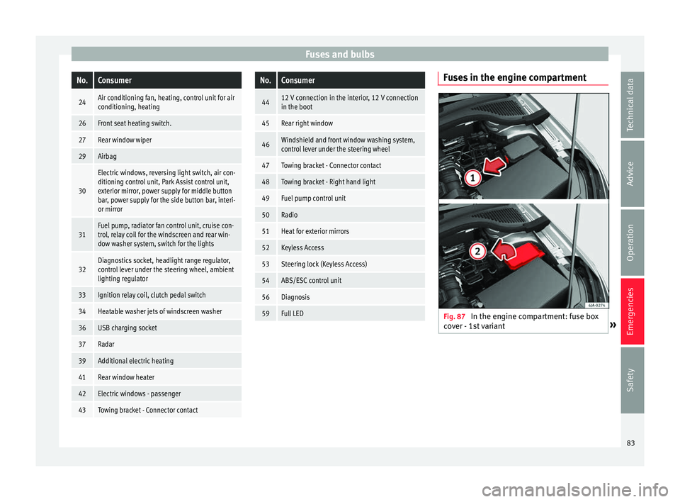
Fuses in the engine compartment
Fig. 87
In the engine compartment: fuse box
c o
v
er - 1st variant » 83
Technical data
Advice
Operation
Emergencies
Safety
Page 87 of 248
Fuses and bulbs
Full-LED headlight system*
F u
l
l-LED headlights handle all light functions
(daylight, side light, turn signal, dipped
beam and route light) with light emitting di-
odes (LEDs) as a light source.
Full-LED headlights are designed to last the
lifetime of the car and light bulbs cannot be
replaced. In case of headlight failure, go to
an authorised workshop to have it replaced.
Double headlight bulb change
Changing bulbs requires a certain degree of
practical skill. If in doubt, we recommend you
have defective bulbs changed by a special-
ised service or, in case of an emergency,
seek professional assistance.
● Switch off the ignition and all of the lights
before c
hanging a bulb.
● Do not touch the glass part of the bulb with
your bar
e hands. The fingerprints left on the
glass will vaporise as a result of the heat gen-
erated by the bulb, reducing bulb life and
causing condensation on the reflector sur-
face, thus reducing effectiveness.
● A bulb must only be replaced by one of the
same type. The type i
s indicated on the bulb,
either on the glass part or on the base.
● There is a storage area for the bulb box in
the spar
e wheel well or below the carpet in
the luggage compartment. WARNING
● Tak e p
articular care when working on com-
ponents in the engine compartment if the en-
gine is warm. Risk of burns.
● Bulbs are highly sensitive to pressure. The
glas
s can break when you touch the bulb,
causing injury.
● When changing bulbs, please take care not
to injure
yourself on sharp parts in the head-
light housing. CAUTION
● Remo v
e the ignition key before working on
the electric system. Otherwise, a short circuit
could occur.
● Switch off the lights and the parking light
before c
hanging a bulb. For the sake of the environment
Please ask your specialist retailer how to dis-
pose of u
sed bulbs in the proper manner. Note
● Dependin g on w
eather conditions (cold or
wet), the front lights, the fog lights, the rear
lights and the turn signals may be temporari-
ly misted. This has no influence on the useful
life of the lighting system. By switching on
the lights, the area through which the beam
of light is projected will quickly be demisted.
However, the edges may continue to be mis-
ted. ●
Ple a
se check at regular intervals that all
lighting (especially the exterior lighting) on
your vehicle is functioning properly. This is
not only in the interest of your own safety,
but also that of all other road users.
● Before changing a bulb, make sure you
have the c
orrect new bulb.
● Do not touch the glass part of the bulb with
your bar
e hands, use a cloth or paper towel
instead. Otherwise, the fingerprints left on
the glass will vaporise as a result of the heat
generated by the bulb, they will be deposited
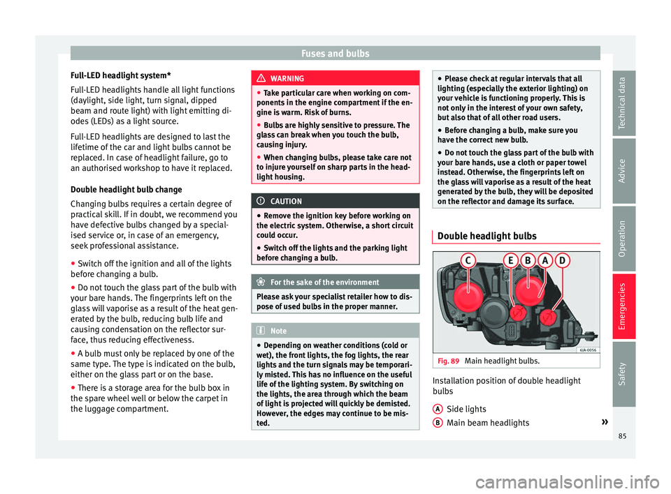
on the reflector and damage its surface. Double headlight bulbs
Fig. 89
Main headlight bulbs. Installation position of double headlight
b
u
l
bs
Side lights
Main beam headlights »
A B
85
Technical data
Advice
Operation
Emergencies
Safety
Page 89 of 248
Fuses and bulbs
– Remo
v
e connector ››› Fig. 93 1 by pulling
outw ar
d.
– Unc
lip the retainer spring ›››
Fig. 93 2 pressing clockwise and inwards.
– Extract the bulb and fit the replacement so
th at
the lug on the b
ase fits into the recess
on the reflector.
– Fit the connector.
– Fit the protective cover. Make sure that the
cov
er fits correctly on the housing during
operation.
– Replace the wheel housing cover.
– Check whether the new bulb is working.
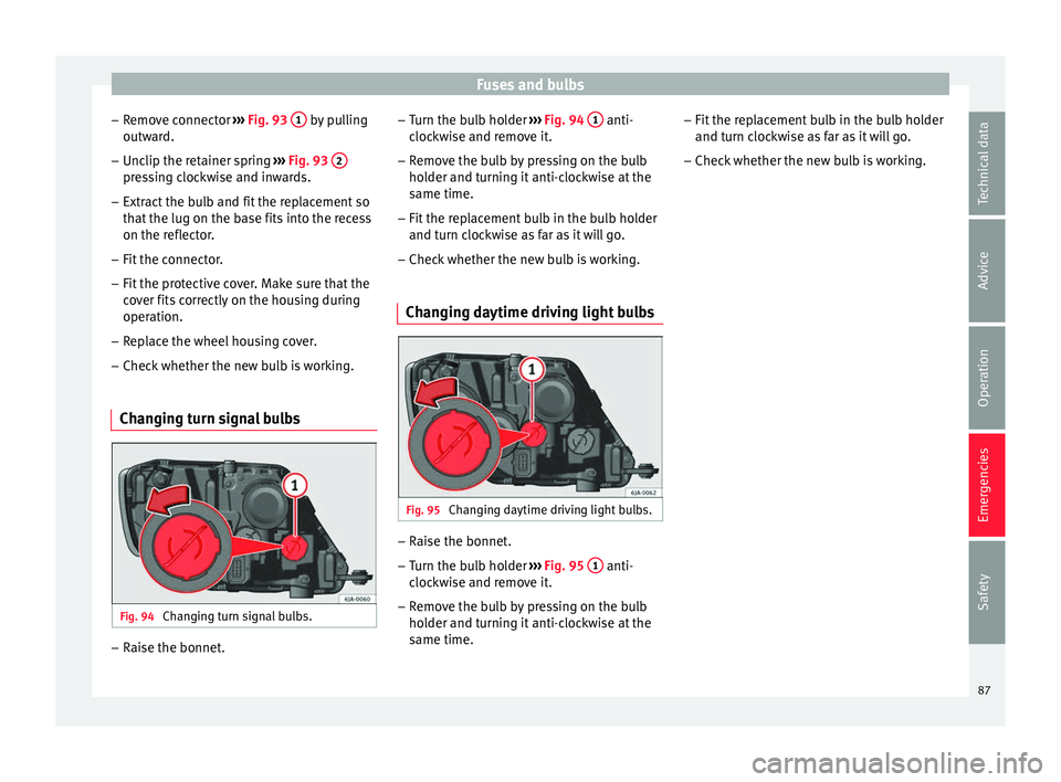
Changing turn signal bulbs Fig. 94
Changing turn signal bulbs. –
Raise the bonnet. –
Turn the b
u
lb holder ››› Fig. 94 1 anti-
c loc
k
wise and remove it.
– Remove the bulb by pressing on the bulb
holder and t
urning it anti-clockwise at the
same time.
– Fit the replacement bulb in the bulb holder
and turn cloc
kwise as far as it will go.
– Check whether the new bulb is working.
Changing daytime driving light bulbs Fig. 95
Changing daytime driving light bulbs. –
Raise the bonnet.
– Turn the bulb holder ›
››
Fig. 95 1 anti-
c loc
k
wise and remove it.
– Remove the bulb by pressing on the bulb
holder and t
urning it anti-clockwise at the
same time. –
Fit the rep
lacement bulb in the bulb holder
and turn clockwise as far as it will go.
– Check whether the new bulb is working.
87
Technical data
Advice
Operation
Emergencies
Safety
Page 91 of 248
Fuses and bulbs
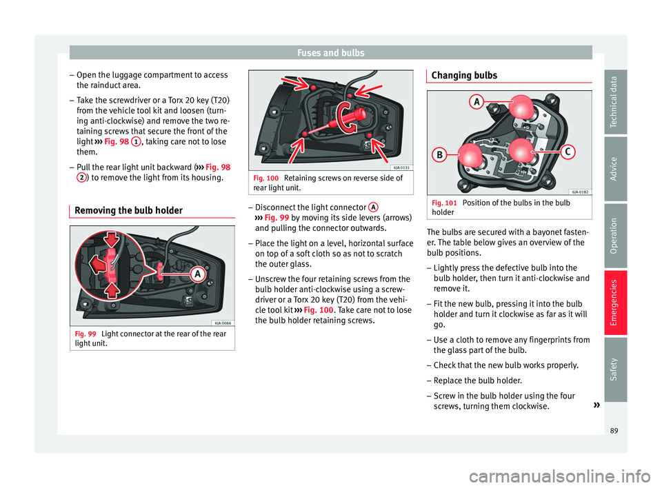
– Open the lug g
ag
e compartment to access
the rainduct area.
– Take the screwdriver or a Torx 20 key (T20)
from the v
ehicle tool kit and loosen (turn-
ing anti-clockwise) and remove the two re-
taining screws that secure the front of the
light ››› Fig. 98 1 , taking care not to lose
them.
– Pull the rear light unit backward ( ››
›
Fig. 98
2 ) to remove the light from its housing.
Removing the bulb holder Fig. 99
Light connector at the rear of the rear
light u
nit
. Fig. 100
Retaining screws on reverse side of
re ar light
unit. –
Disconnect the light connector A ›››
Fig. 99 by mo
ving its side levers (arrows)
and pulling the connector outwards.
– Place the light on a level, horizontal surface
on top of a sof
t cloth so as not to scratch
the outer glass.
– Unscrew the four retaining screws from the
bul
b holder anti-clockwise using a screw-
driver or a Torx 20 key (T20) from the vehi-
cle tool kit ››› Fig. 100. Take care not to lose
the bulb holder retaining screws. Changing bulbs Fig. 101
Position of the bulbs in the bulb
ho l
der The bulbs are secured with a bayonet fasten-
er
.
The t
able below gives an overview of the
bulb positions.
– Lightly press the defective bulb into the
bul
b holder, then turn it anti-clockwise and
remove it.
– Fit the new bulb, pressing it into the bulb
holder and t
urn it clockwise as far as it will
go.
– Use a cloth to remove any fingerprints from
the glas
s part of the bulb.
– Check that the new bulb works properly.
– Replace the bulb holder.
– Screw in the bulb holder using the four
scr
ews, turning them clockwise. »
89
Technical data
Advice
Operation
Emergencies
Safety
Page 93 of 248
Fuses and bulbs
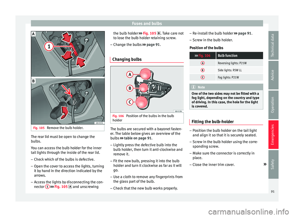
Fig. 105
Remove the bulb holder. The rear lid must be open to change the
b
u
l
bs.
You can access the bulb holder for the inner
tail lights through the inside of the rear lid.
– Check which of the bulbs is defective.
– Open the cover to access the lights, turning
it by
hand in the direction indicated by the
arrows.
– Access the lights by disconnecting the con-
nector 1
› ›
› Fig. 105
and unscrewing the bulb holder
›››
Fig. 105 . Take care not
to lose the bulb holder retaining screw.
– Change the bulbs ›››
page 91.
Changing bulbs Fig. 106
Position of the bulbs in the bulb
ho l
der The bulbs are secured with a bayonet fasten-
er
.
The t
able below gives an overview of the
bulbs ››› table on page 91.
– Lightly press the defective bulb into the
bul
b holder, then turn it anti-clockwise and
remove it.
– Fit the new bulb, pressing it into the bulb
holder and t
urn it clockwise as far as it will
go.
– Use a cloth to remove any fingerprints from
the glas
s part of the bulb.
– Check that the new bulb works properly. –
Re-ins
tall the bulb holder ››› page 91.
– Screw in the bulb holder.
Pos
ition of the bulbs
››› Fig. 106Bulb function
AReversing lights: P21W
BSide lights: R5W LL
CFog lights: P21W Note
One of the two sides may not be fitted with a
fog light, depending on the c
ountry and type
of driving. In this case, the hole for the light
is covered. Fitting the bulb-holder
–
Position the bulb holder on the tail light
and align it so th
at
it is securely seated.
– Screw in the bulb holder using the corre-
sponding s
crew.
– Make sure the connector is correctly in
plac
e.
– Close the inner trim cover. »
91
Technical data
Advice
Operation
Emergencies
Safety