oil level Seat Toledo 2017 Owner's manual
[x] Cancel search | Manufacturer: SEAT, Model Year: 2017, Model line: Toledo, Model: Seat Toledo 2017Pages: 248, PDF Size: 5.86 MB
Page 6 of 248
Table of Contents
Engine management and emission control sys-
t em
. . . . . . . . . . . . . . . . . . . . . . . . . . . . . . . . . . . 167
Driv
ing tips . . . . . . . . . . . . . . . . . . . . . . . . . . . . . 169
Driver assistance systems . . . . . . . . . . . . . . . . . 170
Parking aid . . . . . . . . . . . . . . . . . . . . . . . . . . . . . 170
Rear Assist “Rear View Camera”* . . . . . . . . . . . 175
Cruise speed (Cruise Control)* . . . . . . . . . . . . . 178
Emergency brake assist system (Front As-
sis
t)* . . . . . . . . . . . . . . . . . . . . . . . . . . . . . . . . . . 179
Start-Stop System* . . . . . . . . . . . . . . . . . . . . . . . 183
Fatigue detection (break recommendation)* . . 185
Towing bracket device . . . . . . . . . . . . . . . . . . . . 186
Driving with a trailer . . . . . . . . . . . . . . . . . . . . . . 186
Towing bracket device . . . . . . . . . . . . . . . . . . . . 188
Advice . . . . . . . . . . . . . . . . . . . . . . . . . . . . . . . . 194
Care and maintenance . . . . . . . . . . . . . . . . . . . . 194
Accessories and modifications to the vehi-
cle
. . . . . . . . . . . . . . . . . . . . . . . . . . . . . . . . . . . . 194
Care and cleaning . . . . . . . . . . . . . . . . . . . . . . . 195
Checking and refilling levels . . . . . . . . . . . . . . . 201
Fuel . . . . . . . . . . . . . . . . . . . . . . . . . . . . . . . . . . . 201
Engine compartment . . . . . . . . . . . . . . . . . . . . . 204
Engine oil . . . . . . . . . . . . . . . . . . . . . . . . . . . . . . 207
Coolant . . . . . . . . . . . . . . . . . . . . . . . . . . . . . . . . 210
Brake fluid . . . . . . . . . . . . . . . . . . . . . . . . . . . . . 211
Window washer system . . . . . . . . . . . . . . . . . . . 212
Battery . . . . . . . . . . . . . . . . . . . . . . . . . . . . . . . . . 213
Wheels and tyres . . . . . . . . . . . . . . . . . . . . . . . . 217
Tyres . . . . . . . . . . . . . . . . . . . . . . . . . . . . . . . . . . 217
Spare wheel . . . . . . . . . . . . . . . . . . . . . . . . . . . . 220
Tyre monitoring systems . . . . . . . . . . . . . . . . . . 221
Winter service . . . . . . . . . . . . . . . . . . . . . . . . . . . 222
Technical data . . . . . . . . . . . . . . . . . . . . . . . . 223
Technical specifications . . . . . . . . . . . . . . . . . . 223
Important information . . . . . . . . . . . . . . . . . . . . 223
Information on fuel consumption . . . . . . . . . . . 224 Driving with a trailer . . . . . . . . . . . . . . . . . . . . . . 225
Wheels . . . . . . . . . . . . . . . . . . . . . . . . . . . . . . . . 226
Engine data . . . . . . . . . . . . . . . . . . . . . . . . . . . . . 227
Dimensions . . . . . . . . . . . . . . . . . . . . . . . . . . . . . 233
Index . . . . . . . . . . . . . . . . . . . . . . . . . . . . . . . . . 235
4
Page 24 of 248
The essentialsMenuSubmenuPossible settingDescription
ESC system–Activation of the Electronic Stability Programme (ESC)›››
page 158
TyresTyre monitor systemTyre pressure storing (Calibration)››› page 221
Winter tyresActivation and deactivation of the speed warning. Setting the speed warning value››› page 222
Lights
Light assistMotorway function, turning-on time, automatic lights when raining, one-touch sig-
nalling.››› page 120
Vehicle interior lightingBrightness of instrument panel and controls
“Coming home/Leaving home” func-
tionSwitch-on time of the “Coming home” and “Leaving home” functions››› page 125
Driver assistance
Adaptive Cruise Control (ACC)Activation/deactivation: default distance level, driving profiles.
Front Assist (emergency brake
assist system)Activation/deactivation: Front Assist, advance warning, distance warning display››› page 179
Fatigue detectionActivation/deactivation››› page 185
Parking and manoeu-
vringParking and manoeuvring settingsAutomatically activate front volume, front sound treble, rear volume, rear sound tre-
ble››› page 174
Ambient lighting–Background lighting, switch-off, colour››› page 127
Mirrors and wind-
screen wipersRear view mirrorsActivate/deactivate folding after parking››› page 130
Windscreen wipersActivate and deactivate automatic wipe in case of rain, wipe when reversing››› page 20
Opening and closingElectric windows controlConvenience open function, all, only driver››› page 119
Central locking systemUnlocking doors, automatic lock when driving››› page 111
Instrument panel–
Current consumption, average consumption, convenience consumers, ECO Advice,
travelling time, distance travelled, average speed, digital speed display, speed
warning, oil temperature, reset data “when setting off”, reset data for “total calcula-
tion”
››› page 25
Date and time–Time, summer time, time zone, time format, date, date format››› page 98 22
Page 36 of 248
The essentials
Yellow warning lamps Central warning lamp: additional
information on the instrument
panel display–
Front brake pads worn.›››
page
157
it lights up:
Fault in the ESC, or
disconnection caused by the sys-
tem.
››› page
158
flashes: ESC or ASR activated.
ASR manually deactivated.›››
page
158
ABS faulty or does not work.
Rear fog light switched on.›››
page 18
lights up or flashes:
fault in the
emission control system.››› page
167
it lights up:
pre-heating of diesel
engine.
››› page
169
flashes: fault in the diesel engine
management.
fault in the petrol engine man-
agement.›››
page
169
lights up or flashes:
fault in the
steering system.››› page
153
Tyre pressure too low, or fault in
the tyre pressure monitoring sys-
tem.›››
page
221
Fuel tank almost empty.›››
page
100
Fault in airbag system and seat
belt tensioners.›››
page
67 Other warning lamps
Left or right turn signal.›››
page 19
Hazard warning lights on.››› page
125
Trailer turn signals›››
page
186
it lights up:
Press the foot brake!
flashes: the selector lever locking
button has not engaged.››› page
163
it lights up:
cruise control activa-
ted or speed limiter switched on
and active.
››› page 32
flashes: the speed set by the
speed limiter has been exceeded.
Main beam on or flasher on.›››
page 19
››› in Control and warning lamps on
page 101
››› page 100 On the instrument panel display
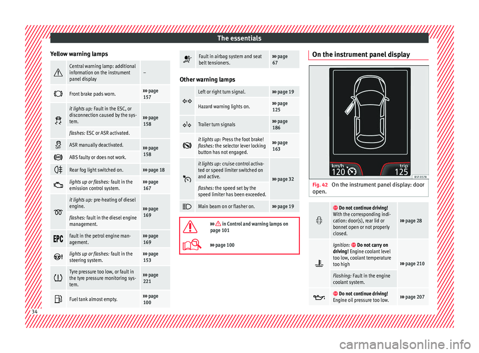
Fig. 42
On the instrument panel display: door
open.
Do not continue driving!
With the corresponding indi-
cation: door(s), rear lid or
bonnet open or not properly
closed.
››› page 28
Ignition: Do not carry on
driving! Engine coolant level
too low, coolant temperature
too high
››› page 210
Flashing: Fault in the engine
coolant system.
Do not continue driving!
Engine oil pressure too low.››› page 207 34
Page 37 of 248
The essentials
Fault in the battery.›››
page 214
Driving light totally or partially
faulty.›››
page 84
Fault in the cornering light
system.››› page 120
Diesel particulate filter
blocked›››
page 168
Level of windscreen washer
fluid too low.›››
page 212
Flashing: Fault in the oil level
detection. Control manually.
›››
page 207Ignition: Insufficient engine
oil.
Fault in the gearbox.›››
page 164
Immobiliser active.›››
page 154
Service interval display›››
page 31
Mobile telephone is connec-
ted via Bluetooth to the origi-
nal telephone device.
›››
Booklet
Radio or
››› Booklet
Navigation
system
Mobile telephone battery
charge meter. Available only
for devices pre-installed in
factory.
Freezing warning. The outside
temperature is lower than
+4°C (+39°F).›››
page 29
Start-Stop system activated.
›››
page 183 Start-Stop system unavaila-
ble.
Low consumption driving sta-
tus›››
page 97
›››
page 97 On the instrument panel
Front passenger front airbag is
disabled (
).
››› page
67
››› in Front passenger front airbag
switch on page 73
››› page 14 Gearbox lever
M anua
l
gearbox Fig. 43
Gear shift pattern of a 5 or 6-speed
m anual
g
earbox. The position of the gears is indicated on the
g
e
arbo
x lever ››› Fig. 43.
● Press the clutch pedal and keep your foot
right down.
● Mo
ve the gearbox lever to the required po-
sition.
● Rel
ease the clutch.
Selecting r
everse gear
● Press the clutch pedal and keep your foot
right down.
● W
ith the gearbox lever in neutral, push it
downw
ards, move it to the left as far as it will
go and then forwards to select reverse
››› Fig. 43 R .
» 35
Page 43 of 248

The essentials
Oil Fig. 50
Engine oil dipstick. Fig. 51
In the engine compartment: Engine
oil fi
ller cap. The level is measured using the dipstick loca-
t
ed in the en
gine c
ompartment
››› page 207.
The oil should leave a mark between zones A and
C . It should never exceed zone
A .
● Zone A : Do not add oil.
● Zone B : You can add oil but keep the level
in th at
zone. ●
Zone C : Add oil up to zone
B .
T op
pin
g up engine oil
● Unscrew cap from engine oil filler opening
›››
Fig. 51.
● Add oil slowly.
● At the same time, check the level to ensure
you do not a
dd too much. ●
When the oil l
evel reaches at least zone B ,
u n
s
crew the engine oil filler cap carefully.
Engine oil additives
No type of additive should be mixed with the
engine oil. The deterioration caused by these
additives is not covered by the warranty. » 41
Page 44 of 248
The essentials
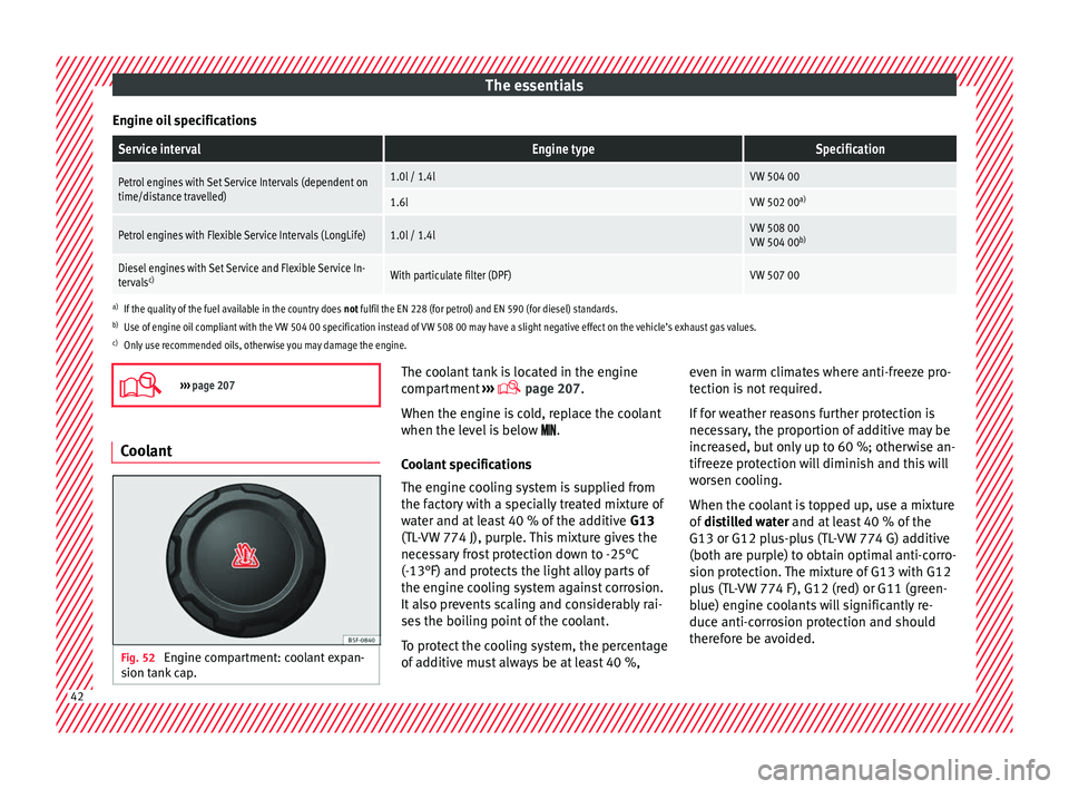
Engine oil specificationsService intervalEngine typeSpecification
Petrol engines with Set Service Intervals (dependent on
time/distance travelled)1.0l / 1.4lVW 504 00
1.6lVW 502 00 a)
Petrol engines with Flexible Service Intervals (LongLife)1.0l / 1.4lVW 508 00
VW 504 00b)
Diesel engines with Set Service and Flexible Service In-
tervalsc)With particulate filter (DPF)VW 507 00
a)
If the quality of the fuel available in the country does not fulfil the EN 228 (for petrol) and EN 590 (for diesel) standards.
b) Use of engine oil compliant with the VW 504 00 specification instead of VW 508 00 may have a slight negative effect on the vehicle’s exhaust gas values.
c) Only use recommended oils, otherwise you may damage the engine.
››› page 207 Coolant
Fig. 52
Engine compartment: coolant expan-
s ion t
ank
cap. The coolant tank is located in the engine
c
omp
ar
tment ›››
page 207.
When the engine is cold, replace the coolant
when the level is below .
Coolant specifications
The engine cooling system is supplied from
the factory with a specially treated mixture of
water and at least 40 % of the additive G13
(TL-VW 774 J), purple. This mixture gives the
necessary frost protection down to -25°C
(-13°F) and protects the light alloy parts of
the engine cooling system against corrosion.
It also prevents scaling and considerably rai-
ses the boiling point of the coolant.
To protect the cooling system, the percentage
of additive must always be at least 40 %, even in warm climates where anti-freeze pro-
tection is
not required.
If for weather reasons further protection is
necessary, the proportion of additive may be
increased, but only up to 60 %; otherwise an-
tifreeze protection will diminish and this will
worsen cooling.
When the coolant is topped up, use a mixture
of distilled water and at least 40 % of the
G13 or G12 plus-plus (TL-VW 774 G) additive
(both are purple) to obtain optimal anti-corro-
sion protection. The mixture of G13 with G12
plus (TL-VW 774 F), G12 (red) or G11 (green-
blue) engine coolants will significantly re-
duce anti-corrosion protection and should
therefore be avoided. 42
Page 102 of 248
Operation
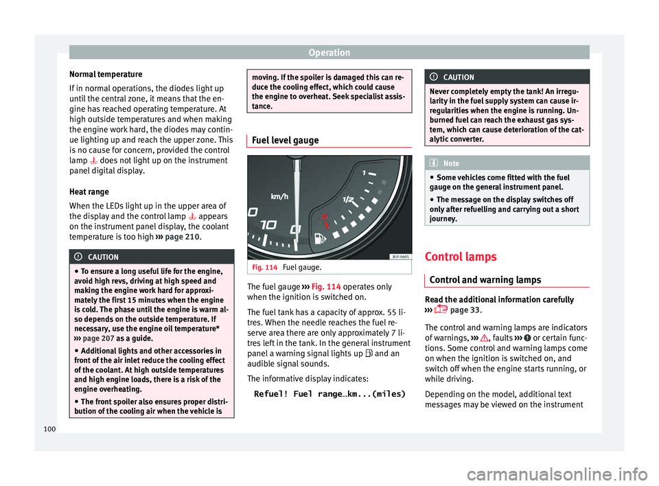
Normal temperature
If in norm
al
operations, the diodes light up
until the central zone, it means that the en-
gine has reached operating temperature. At
high outside temperatures and when making
the engine work hard, the diodes may contin-
ue lighting up and reach the upper zone. This
is no cause for concern, provided the control
lamp does not light up on the instrument
panel digital display.
Heat range
When the LEDs light up in the upper area of
the display and the control lamp appears
on the instrument panel display, the coolant
temperature is too high ››› page 210. CAUTION
● To en s
ure a long useful life for the engine,
avoid high revs, driving at high speed and
making the engine work hard for approxi-
mately the first 15 minutes when the engine
is cold. The phase until the engine is warm al-
so depends on the outside temperature. If
necessary, use the engine oil temperature*
››› page 207 as a guide.
● Additional lights and other accessories in
front of
the air inlet reduce the cooling effect
of the coolant. At high outside temperatures
and high engine loads, there is a risk of the
engine overheating.
● The front spoiler also ensures proper distri-
bution of the c
ooling air when the vehicle is moving. If the spoiler is damaged this can re-
duce the c
oo
ling effect, which could cause
the engine to overheat. Seek specialist assis-
tance. Fuel level gauge
Fig. 114
Fuel gauge. The fuel gauge
››
›
Fig. 114 operates only
when the ignition is switched on.
The fuel tank has a capacity of approx. 55 li-
tres. When the needle reaches the fuel re-
serve area there are only approximately 7 li-
tres left in the tank. In the general instrument
panel a warning signal lights up and an
audible signal sounds.
The informative display indicates:
Refuel! Fuel range…km...(miles) CAUTION
Never completely empty the tank! An irregu-
larity in the f
uel supply system can cause ir-
regularities when the engine is running. Un-
burned fuel can reach the exhaust gas sys-
tem, which can cause deterioration of the cat-
alytic converter. Note
● Some v ehic
les come fitted with the fuel
gauge on the general instrument panel.
● The message on the display switches off
only af
ter refuelling and carrying out a short
journey. Control lamps
C ontr
o
l and warning lamps Read the additional information carefully
› ›
›
page 33.
The control and warning lamps are indicators
of warnings, ››› , faults
››
›
or certain func-
tion s.
Some c
ontrol and warning lamps come
on when the ignition is switched on, and
switch off when the engine starts running, or
while driving.
Depending on the model, additional text
messages may be viewed on the instrument
100
Page 170 of 248
Operation
●
Do not ap p
ly wax underneath the vehicle
around the area of the exhaust system: Fire
hazard! Note
While the control lamps , , or r
e-
m ain lit, ther
e may be engine problems, fuel
consumption may increase and the engine
may lose power. Catalytic converter
An exhaust gas emission control system (cat-
alytic
c
on
verter) that functions perfectly is vi-
tally important for vehicle operation that re-
spects the environment.
Please observe the following indications:
● Refuel only using unleaded petrol in petrol
engine v
ehicles ››› page 202.
● Do not add too much oil to the engine
›››
page 209, Checking engine oil level .
● Do not switch off the ignition while driving.
If y
ou are required to drive in a country where
unleaded fuel is not available, when return-
ing to a country where using a catalytic con-
verter is obligatory, the catalytic converter
must be replaced. CAUTION
● Never c omp
letely empty the tank! An irreg-
ular fuel supply can cause ignition faults,
which can result in damage to a substantial
amount of engine parts and the exhaust sys-
tem.
● Refuelling just once with leaded petrol dis-
able
s the exhaust system! Particulate filter (diesel
en
gines) The diesel engine particulate filter eliminates
mo
s
t
of the soot from the exhaust gas sys-
tem. Under normal driving conditions, the fil-
ter cleans itself. The diesel particulate filter is
cleaned automatically without need for indi-
cation by the warning lamp . This may be
noticed because the engine idle speed in-
creases and an odour may be detected.
If automatic filter purification cannot be car-
ried out (because only short trips are taken,
for example), soot will accumulate on the fil-
ter and the Diesel particulate filter warning
lamp will switch on.
Facilitate the automatic filter cleaning proc-
ess by driving in the following manner: drive
for approximately 15 minutes at a minimum
speed of 60 km/h (37 mph) in 4th or 5th gear
(automatic gearbox: gear S). Maintain the en-
gine speed at approximately 2,000 rpm. The
rise in temperature causes the soot on the fil- ter to burn. On completion of the cleaning
the warning l
amp will switch off.
If the lamp does not turn off, or the three
lamps turn on (particulate filter , fault in
the emission control system and glow
plugs ), drive the vehicle to a specialised
workshop and have the fault repaired at the
earliest opportunity. WARNING
● Alw a
ys drive according to the road weather
conditions, the terrain and traffic.
● The particulate filter attains very high tem-
peratur
es. Therefore, do not park the vehicle
in places where the exhaust pipe could come
into contact with dry grass or with highly-
flammable materials. Risk of fire! CAUTION
While the warning lamp is lit
up, the fuel
consumption is high, and in certain condi-
tions, the engine power is reduced. Note
● In order f or the p
articulate filter to burn off
soot in a correct manner, avoid carrying out
frequent short journeys.
● Using diesel fuel with a high sulphur count
can con
siderably reduce the useful life of the
particulate filter. The specialised service pro-
vides information about the countries where
fuel with a high sulphur content is used. 168
Page 172 of 248
Operation
WARNING
● Drivin g thr
ough water, dirt and mud can re-
duce braking capability and prolong the brak-
ing distance – Risk of accident!
● Do not carry out any sudden or strong brak-
ing manoeu
vres after driving through water.
● Clean and dry the brakes as soon as possi-
ble af
ter driving through water by breaking
intermittently. Carry out braking in order to
dry the brakes and clean the brake discs only
if traffic so permits. Do not put other drivers
at risk. CAUTION
● In the event of
driving through water, parts
of the vehicle can be seriously damaged,
such as the engine, gearbox, catalytic con-
verter, suspension or the electrical system.
● Oncoming vehicles that drive through wa-
ter can c
ause waves that exceed your vehi-
cle's permitted level for driving through wa-
ter.
● There may be pot-holes mud or rocks under
the water th
at can hinder or prevent driving
through water.
● Do not drive through salt water. The salt
can cau
se rust. All components that are ex-
posed to salt water must be rinsed immedi-
ately with fresh water. Note
After driving through water we recommend
that
you contact a specialised service for an
inspection. Preventing damage to the vehicle
In order to prevent damage to the vehicle,
tak
e s
pecial care:
● on roads that are in poor condition,
● when mounting kerbs,
● when approaching very steep ramps, etc.,
● with the parts of the vehicle situated on the
low er p
art of the vehicle, i.e. the spoiler, the
exhaust pipe.
This applies especially to vehicles with a very
low suspension (sport) and when the vehicle
is fully loaded. Driver assistance systems
P ark
in
g aid
General information Assorted assistance systems – which vary
depending on the equipment
fitt
ed in the car
– will help you when parking or manoeu-
vring.
The rear parking aid is an audible assistant
that warns about obstacles located behind
the vehicle ›››
page 171.
During parking, Parking System Plus assists
the driver by visually and audibly warning
them about obstacles detected in front and
behind the vehicle ›››
page 172. WARNING
● Alw a
ys pay attention, also when looking
straight ahead, to traffic and the vehicle sur-
roundings. The assistance systems are not a
replacement for driver awareness. When in-
serting or removing the vehicle from a park-
ing space, or when performing similar ma-
noeuvres the driver always assumes the re-
sponsibility.
● Adapt your speed and driving style at all
times t
o suit visibility, weather, road and traf-
fic conditions.
● The ultrasound sensors have blind spots in
which ob
stacles and people are not170
Page 203 of 248
Checking and refilling levels
Check the condition of all seat belts at regu-
l ar int
er
vals.
Very soiled belts may not retract properly. WARNING
● The seat belt
s should never be removed
from the vehicle for cleaning.
● Never clean using chemical products, as
chemica
l detergents destroy the fabric. En-
sure that the seat belts do not come into con-
tact with corrosive fluids such as acids, etc.
● If you find any damage to the belt webbing,
belt fitting
s, the belt retractor or the buckle,
the belt in question must be replaced by an
Official Service.
● Make sure that the inertia reel seat belts
are comp
letely dry before allowing them to
retract. Checking and refilling levels
F uel
R ef
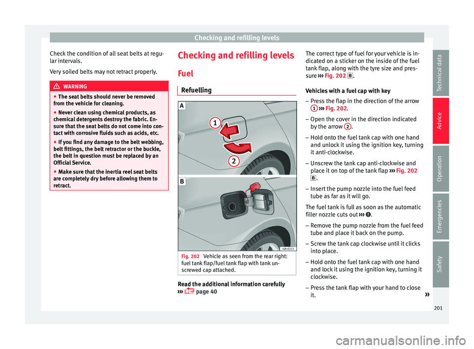
uelling Fig. 202
Vehicle as seen from the rear right:
f uel t
ank flap/fuel tank flap with tank un-
screwed cap attached. Read the additional information carefully
› ›
›
page 40 The correct type of fuel for your vehicle is in-
dicated on a s
ticker on the inside of the fuel
tank flap, along with the tyre size and pres-
sure ››› Fig. 202 .
Vehicles with a fuel cap with key
– Press the flap in the direction of the arrow
1
› ››
Fig. 202
.
– Open the c
over in the direction indicated
by the arr
ow 2 .
– Hold onto the fuel tank cap with one hand
and u n
loc
k it using the ignition key, turning
it anti-clockwise.
– Unscrew the tank cap anti-clockwise and
plac
e it on top of the tank flap ››› Fig. 202
.
– Insert the pump nozzle into the fuel feed
tube as
far as it will go.
The fuel tank is full as soon as the automatic
filler nozzle cuts out ››› .
– Remove the pump nozzle from the fuel feed
tube and p
l
ace it back on the pump.
– Screw the tank cap clockwise until it clicks
into pl
ace.
– Hold onto the fuel tank cap with one hand
and lock it
using the ignition key, turning it
clockwise.
– Press the tank flap with your hand to close
it. »
201
Technical data
Advice
Operation
Emergencies
Safety