instrument panel SKODA CITIGO 2014 1.G Owner's Manual
[x] Cancel search | Manufacturer: SKODA, Model Year: 2014, Model line: CITIGO, Model: SKODA CITIGO 2014 1.GPages: 164, PDF Size: 12.08 MB
Page 13 of 164
WARNING (Continued)■When driving, hold the steering wheel with both hands firmly on the out-
er edge in the “9 o'clock” and “3 o'clock” position. Never hold the steering
wheel in the “12 o'clock” position or in any other way (e.g. in the middle or
inner edge of the steering wheel). In such cases, you could severely injure
the arms, hands and head when the driver airbag is deployed.■
Ensure that there are no objects in the driver's footwell as they may get
caught behind the pedals when driving or applying the braking. You would
then no longer be able to operate the clutch, brake or acceleration pedals.
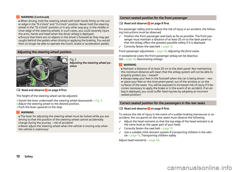
Adjusting the steering wheel position
Fig. 2
Adjusting the steering wheel po-
sition
Read and observe on page 9 first.
The height of the steering wheel can be adjusted.
›
Swivel the lever underneath the steering wheel downwards » Fig. 2.
›
Adjust the steering wheel to the desired position.
›
Push the lever upwards to the stop.
WARNING■
The lever for adjusting the steering wheel must be locked while you are
driving so that the position of the steering wheel cannot accidentally
change during the journey – risk of accident!■
Never adjust the steering wheel when the vehicle is moving only when
the vehicle is stationary!
Correct seated position for the front passenger
Read and observe
on page 9 first.
For passenger safety and to reduce the risk of injury in an accident, the follow-ing instructions must be observed.
Position the front passenger seat back as far as possible. The front pas-
senger must maintain a distance of at least 25 cm to the dash panel so
that the airbag offers the greatest possible safety if it is deployed.
Correctly fasten the seat belt » page 13.
Front passenger adjustment » page 56, Adjusting the front seats .
In exceptional cases the front passenger airbag can be deactiva-
ted » page 18 , Deactivating airbags .
WARNING■
Maintain a distance of at least 25 cm to the dash panel. Not maintaining
this minimum distance will mean that the airbag system will not be able to
properly protect you – hazard!■
Always keep your feet in the footwell when the car is being driven – nev-
er place your feet on the instrument panel, out of the window or on the
surfaces of the seats. You will be exposed to increased risk of injury if it be-
comes necessary to apply the brake or in the event of an accident. If an air-
bag is deployed, you could suffer fatal injuries by adopting an incorrect
seated position!
Correct seated position for the passengers in the rear seats
Read and observe
on page 9 first.
To reduce the risk of injury in the event of a sudden braking manoeuvre or anaccident, the occupants on the rear seats must observe the following.
Adjust the head restraint so that the top edge of the head restraint is at
the same level as the upper part of your head.
Correctly fasten the seat belt » page 13.
Use a suitable child restraint system if transporting children in the vehi- cle » page 19 , Transporting children safely .
Adjust head restraints » page 56.
10Safety
Page 18 of 164
Airbag system
Description of the airbag system
Introduction
This chapter contains information on the following subjects:
System description
15
Airbag deployment
15
The airbag system provides, as a supplement to the seat belts, additional oc-
cupant protection during severe frontal and side collisions.
WARNING■ An airbag can only offer you optimal protection in combination with a
fastened seat belt .■
The airbag is not a substitute for the seat belt, but instead forms part of
the complete passive vehicle safety concept.
■
To ensure passengers are protected with the greatest possible effect
when the airbag is deployed, the front seats must be correctly adjusted to
match the body size » page 9, Correct and safe seated position .
■
If you do not fasten the seat belts when driving, lean too far forward or
adopt an incorrect seated position, you are exposing yourself to increased
risk of injury in the event of an accident.
WARNINGInformation on the use of the airbag system■If there is a fault, the airbag system must be checked by a specialist ga-
rage immediately. Otherwise, there is a risk that the airbag will not be de-
ployed in the event of an accident.■
No modifications of any kind must be made to parts of the airbag system.
■
Any work on the airbag system including the installation and removal of
system components due to other repair work (e.g. removal of the steering
wheel) must only be carried out by a specialist garage.
■
Never make any changes to the front bumper or bodywork.
■
It is prohibited to manipulate individual parts of the airbag system, as this
might result in the airbag being deployed.
■
The protective function of the airbag system is sufficient for only one ac-
cident. The airbag system must then be replaced if the airbag has been de-
ployed.
System description
Read and observe
on page 15 first.
The functional status of the airbag system is indicated by the indicator light
in the instrument cluster » page 38.
When the airbags are deployed, they fill with gas and inflate.
A grey white or red, non-harmful gas is released when the airbag is inflated.
This is perfectly normal and is not an indication of a fire in the vehicle.
Depending on the vehicle equipment, the airbag system consists of the
following modules.
› Electronic control unit.
› Front airbag for the driver and the front passenger
» page 16.
› Side airbags Head-thorax
» page 17;
› Airbag warning light in the instrument cluster
» page 38,
Airbag system
.
› Key switch for the front passenger airbag
» page 18.
› Warning light for the front passenger airbag deactivation/activation in the
middle of the dash panel » page 18.
Note
■
The airbag system needs no maintenance during its working life.■If you sell your vehicle, provide the complete vehicle documentation to the
new owner. Please note that the information relating to the possibility of de-
activating the front passenger airbag must be included!■
When disposing of vehicle or parts of the airbag system, it is important to
comply with the national legal requirements.
Airbag deployment
Read and observe
on page 15 first.
The airbags inflate in fractions of a second and at a high speed in order to beable to offer additional protection in the event of an accident.
The airbag system is only functional when the ignition is switched on.
In certain accident situations, several airbags may be deployed simultaneously.
The airbags are not deployed in the case of minor frontal and side collisions,
rear-end collisions, tilting of the vehicle and vehicle rollover.
15Airbag system
Page 41 of 164
Engine performance checkRead and observe
on page 34 first.
If the indicator light
illuminates , there is a fault in the engine control. The
system allows the vehicle to run in emergency mode.
Seek assistance from a specialist garage immediately.
Airbag system
Read and observe
on page 34 first.
Monitoring the airbag system
If the warning light does not go out for some seconds after the ignition has
been switched on or illuminates while you are driving, there is a fault in the
system »
. This also applies if the warning light does not come on when the
ignition is switched on.
The operational capability of the airbag system is monitored electronically, in-
cluding when one of the airbags is switched off.
One of the airbags or a belt tensioner has been disabled by the diagnostic
tool
› The warning light
illuminates for approx. 4 seconds after switching on the
ignition and then flashes again for approx. 12 seconds afterwards.
The front passenger airbag has been disabled with the key switch
› The warning light
illuminates for a few seconds when the ignition is
switched on;
› The deactivated airbag is indicated by the illumination of the warning light
in the middle of the dash panel
» page 18, Deactivating
the front passenger airbag .
WARNINGWhen a fault in the airbag system occurs, there is a risk of the system not
being triggered in the event of an accident. Therefore, this must be
checked immediately by a specialized garage.
Handbrake - automatic transmission
Read and observe
on page 34 first.
If the warning light
illuminates or blinks, engage the handbrake.
Further information » page 80, Automated transmission .
Brake pedal (automatic transmission)
Read and observe
on page 34 first.
If the warning light
illuminates , operate the brake pedal.
Further information » page 80, Automated transmission .
Turn signal system
Read and observe
on page 34 first.
Either the left or right
indicator light
flashes depending on the position of
the control lever.
If there is a fault in the turn signal system, the warning light flashes at twice
its normal rate.
Switching off the hazard warning light system is switched on will cause all of
the turn signal lights as well as both warning lights to flash.
Cruise control system
Read and observe
on page 34 first.
The warning light
illuminates when the cruise control is active.
Main beam
Read and observe
on page 34 first.
The warning light
illuminates when the main beam or the headlight flasher
is operated.
/ Safety belt (belt status display) - rear seat
Read and observe
on page 34 first.
After switching on the ignition, illumination takes place in the display of the
instrument cluster for 30 s of the symbols or
.
38Using the system
Page 84 of 164
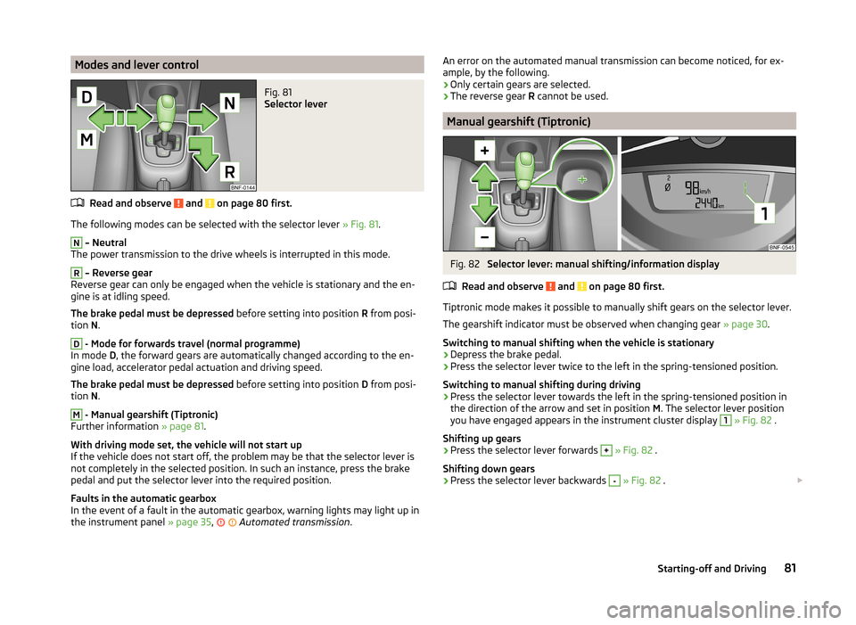
Modes and lever controlFig. 81
Selector lever
Read and observe and on page 80 first.
The following modes can be selected with the selector lever » Fig. 81.
N
– Neutral
The power transmission to the drive wheels is interrupted in this mode.
R
– Reverse gear
Reverse gear can only be engaged when the vehicle is stationary and the en-
gine is at idling speed.
The brake pedal must be depressed before setting into position R from posi-
tion N.
D
- Mode for forwards travel (normal programme)
In mode D, the forward gears are automatically changed according to the en-
gine load, accelerator pedal actuation and driving speed.
The brake pedal must be depressed before setting into position D from posi-
tion N.
M
- Manual gearshift (Tiptronic)
Further information » page 81.
With driving mode set, the vehicle will not start up
If the vehicle does not start off, the problem may be that the selector lever is
not completely in the selected position. In such an instance, press the brake
pedal and put the selector lever into the required position.
Faults in the automatic gearbox
In the event of a fault in the automatic gearbox, warning lights may light up in
the instrument panel » page 35,
Automated transmission
.
An error on the automated manual transmission can become noticed, for ex-
ample, by the following.
› Only certain gears are selected.
› The reverse gear
R cannot be used.
Manual gearshift (Tiptronic)
Fig. 82
Selector lever: manual shifting/information display
Read and observe
and on page 80 first.
Tiptronic mode makes it possible to manually shift gears on the selector lever. The gearshift indicator must be observed when changing gear » page 30.
Switching to manual shifting when the vehicle is stationary
›
Depress the brake pedal.
›
Press the selector lever twice to the left in the spring-tensioned position.
Switching to manual shifting during driving
›
Press the selector lever towards the left in the spring-tensioned position in
the direction of the arrow and set in position M. The selector lever position
you have engaged appears in the instrument cluster display
1
» Fig. 82 .
Shifting up gears
›
Press the selector lever forwards
+
» Fig. 82 .
Shifting down gears
›
Press the selector lever backwards
-
» Fig. 82 .
81Starting-off and Driving
Page 139 of 164
CAUTION■“Never repair” fuses and also do not replace them with a fuse of a higher am-
perage – risk of fire! This may also cause damage at another part of the electri-
cal system.■
A blown fuses is recognisable by the molten metal strip. Replace the faulty
fuse with a new one of the same amperage.
■
If a newly inserted fuse burns through again, then a specialist should be con-
sulted immediately.
Note
■ We recommend always carrying replacement fuses in the vehicle. A box of
replacement fuses can be purchased from ŠKODA Original Accessories.■
There can be several power consuming devices for one fuse.
■
Multiple fuses may exist for a single power consuming device.
Fuses on the underside of the dash panel
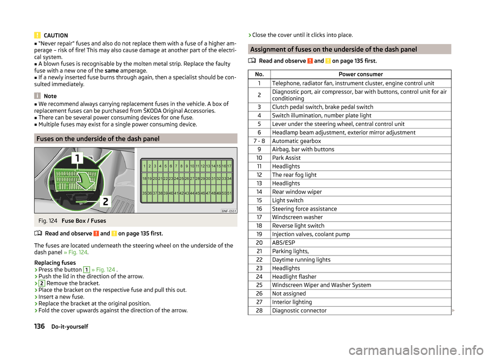
Fig. 124
Fuse Box / Fuses
Read and observe
and on page 135 first.
The fuses are located underneath the steering wheel on the underside of the
dash panel » Fig. 124.
Replacing fuses
›
Press the button
1
» Fig. 124 .
›
Push the lid in the direction of the arrow.
›2
Remove the bracket.
›
Place the bracket on the respective fuse and pull this out.
›
Insert a new fuse.
›
Replace the bracket at the original position.
›
Fold the cover upwards against the direction of the arrow.
›Close the cover until it clicks into place.
Assignment of fuses on the underside of the dash panel
Read and observe
and on page 135 first.
No.Power consumer1Telephone, radiator fan, instrument cluster, engine control unit2Diagnostic port, air compressor, bar with buttons, control unit for air
conditioning3Clutch pedal switch, brake pedal switch4Switch illumination, number plate light5Lever under the steering wheel, central control unit6Headlamp beam adjustment, exterior mirror adjustment7 - 8Automatic gearbox9Airbag, bar with buttons10Park Assist11Headlights12The rear fog light13Headlights14Rear window wiper15Light switch16Steering force assistance17Windscreen washer18Reverse light switch19Injection valves, coolant pump20ABS/ESP21Parking lights,22Daytime running lights23Headlights24Headlight flasher25Windscreen Wiper and Washer System26Not assigned27Interior lighting28Diagnostic connector 136Do-it-yourself
Page 141 of 164
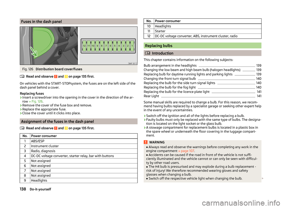
Fuses in the dash panelFig. 126
Distribution board cover/fuses
Read and observe
and on page 135 first.
On vehicles with the START-STOPsystem, the fuses are on the left side of the
dash panel behind a cover.
Replacing fuses
›
Insert a screwdriver into the opening in the cover in the direction of the ar-
row » Fig. 126 .
›
Remove the cover of the fuse box and remove.
›
Replace the appropriate fuse.
›
Close the cover until it clicks into place.
Assignment of the fuses in the dash panel
Read and observe
and on page 135 first.
No.Power consumer1ABS/ESP2Instrument cluster3Radio, diagnosis4DC-DC voltage converter, starter relay, bar with buttons5Not assigned6Not assigned7Not assigned8Not assigned9HeadlightsNo.Power consumer10Headlights11Starter12DC-DC voltage converter, ABS, instrument cluster, radio
Replacing bulbs
Introduction
This chapter contains information on the following subjects:
Bulb arrangement in the headlights
139
Changing the low beam and high beam bulb (halogen headlights)
139
Replacing bulb for daytime running lights and parking lights
139
Changing the front turn signal bulb
140
Replacing the bulb for the side turn signal lights
140
Replacing the bulb for the fog light
140
Replacing the bulb for the licence plate light
141
Rear Light
141
Some manual skills are required to change a bulb. For this reason, we recom-
mend having bulbs replaced by a specialist garage or seeking other expert help
in the event of any uncertainties.
› Switch off the ignition and all of the lights before replacing a bulb.
› Faulty bulbs must only be replaced with the same type of bulbs. The designa-
tion is located on the light socket or the glass bulb.
› A stowage compartment for replacement bulbs is located in a plastic box in
the spare wheel or underneath the floor covering in the luggage compart-
ment.
WARNING■ Always read and observe the warnings before completing any work in the
engine compartment » page 107.■
Accidents can be caused if the road in front of the vehicle is not suffi-
ciently illuminated and the vehicle cannot or can only be seen with difficul-
ty by other road users.
■
The H4 bulb is pressurised and may explode during a bulb replacement -
risk of injury! We therefore recommended wearing gloves and safety
glasses when changing a bulb.
■
Switch off the respective vehicle light when changing the bulb.
138Do-it-yourself
Page 154 of 164
Refuelling104
Refuelling - natural gas105
Fuel consumption144
Fuses Assignment
135
Assignment of fuses in the dash panel138
Assignment of fuses on the underside of the dash panel
136
Colour coding135
Fuse assignment in the engine compartment137
Replacing135
G
Gear changing Gear stick
79
Gear recommendation30
General view Cockpit
27
Genuine parts94
H
Handbrake
79
Warning light34
Handbrake - automatic transmission Warning light
38
Hazard warning light system50
HBA85
Head-Thorax17
Headlights Bulb arrangement
139
Driving abroad51
Head restraints56
Adjust height56
Headrest, removing and installing
57
Heating70
Controls71
Exterior mirrors54
Rear window52
Seats57
HHC85
Hill Hold Control (HHC)85
Horn27
Hydraulic Brake Assist (HBA)85
I
Ignition lock
77
Immobilizer76
Inertia reels14
Instrument cluster28
Counter for distance driven30
Fuel reserve display29
Gear recommendation30
Memory of the multi-function display31
Multi-function display30
Overview28
see instrument cluster28
Service interval display30
Speedometer28
Tachometer29
Instruments see instrument cluster
28
Interior care101
Natural leather101
ISOFIX22
J
Jack
122
- fit126
Maintenance100
Jump-starting130
K
Key Lock
40
Start the engine77
Unlock40
L
Lashing eyes
66
Leather Natural leather care
101
Lever Main beam
49
Turn signal49
Wiper53
lever control81
See lever control81
Light Cockpit
51
Dimmed headlights48
Headlight range control48
on and off48
Parking light51
Sidelights48
Lighting Luggage compartment
65
Light on and off48
Lights48
Daylight running49
Fog lights50
Hazard warning light system50
Headlight flasher49
Main beam49
Rear fog light50
Replacing bulbs138
Turn signal49
Warning lights33
Loading floor68
Lock Key
40
Lock/unlock steering lock76
Locking Door opening lever
42
Remote control41
Locking and unlocking the vehicle from the in- side
43
151Index