fuse box SKODA CITIGO 2015 1.G Owner's Manual
[x] Cancel search | Manufacturer: SKODA, Model Year: 2015, Model line: CITIGO, Model: SKODA CITIGO 2015 1.GPages: 160, PDF Size: 23.1 MB
Page 37 of 160

At a speed of more than approximately 20 km/h the warning light flashes
and an audible warning sounds at a time.
The warning signal is switched of and the
indicator light is permanently lit if
the driver and front passenger have not fastened their seat belts within the
next 90 seconds.
Alternator
Read and observe
on page 34 first.
illuminates - the battery is not being charged whilst the engine is running.
Seek help from a specialist garage.
CAUTION
If in addition to the symbol the symbol » page 35 illuminates while driv-
ing, stop driving - risk of engine damage! Switch off the engine and seek as-
sistance from a specialist garage.
Engine oil pressure too low
Read and observe
on page 34 first.
lights up or flashes - the engine oil pressure is too low.
An audible signal sounds as a warning.
›
Stop the vehicle, switch off the engine, and check the engine oil level
» page 109 , Checking the oil level .
If the warning light illuminates or flashes, do not drive any further, even if
the oil level is correct! Switch off the engine and seek assistance from a spe-
cialist garage.
CAUTION
■ The oil pressure light is not an oil level indicator! One should therefore
check the oil level at regular intervals, preferably after every refuelling stop.■
If for some reason, it is not possible to top up the engine oil under the cur-
rent circumstances,
do not continue driving! Switch off the engine and seek
assistance from a specialist garage.
Coolant
Read and observe
on page 34 first.
lights up or flashes - the coolant temperature is too high or the coolant lev-
el is too low.
An audible signal sounds as a warning tone.
›
Stop the vehicle, switch off the engine, and allow the engine to cool down.
›
Check the coolant level, if necessary top up the coolant.
If the coolant is within the specified range, the cooling fan may be malfunc-
tioning.
›
Switch off the ignition.
›
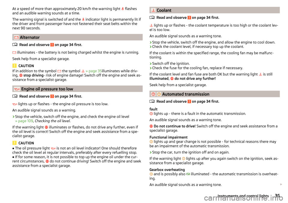
Check the fuse for the cooling fan, replace if necessary.
If the coolant level and fan fuse are both OK but the warning light is still
illuminated ,
do not drive any further!
Seek help from a specialist garage.
Automated transmission
Read and observe
on page 34 first.
fault
lights up - there is a fault in the automatic transmission.
An audible signal sounds as a warning tone.
Do not continue to drive! Switch off the engine and seek assistance from a
specialist garage.
Functional impairment
lights up and gear change is not possible - for technical reasons there may
be an impairment of the automatic transmission.
›
Stop the car, turn the ignition off and on again.
If the warning light lights up after you again switch on the ignition, seek as-
sistance from a specialist garage.
Gearbox overheating
and is possibly also
illuminated - the automatic transmission is overheat-
ing.
An audible signal sounds as a warning tone.
35Instruments and control lights
Page 137 of 160

CAUTION■“Never repair” fuses and also do not replace them with a fuse of a higher am-
perage – risk of fire! This may also cause damage at another part of the electri-
cal system.■
If a newly inserted fuse blows again after a short time, have the electrical
system checked as quickly as possible by a specialist garage.
■
A blown fuses is recognisable by the molten metal strip. Replace the faulty
fuse with a new one of the same amperage.
Note
■
We recommend always carrying replacement fuses in the vehicle. A box of
replacement fuses and bulbs can be purchased from ŠKODA Original Accesso-
ries.■
There can be several power consuming devices for one fuse.
■
Multiple fuses may exist for a single power consuming device.
Fuses in the dash panel
Fig. 134
Remove the fuse box cover.
Read and observe and on page 134 first.
The fuses are located underneath the steering wheel on the underside of the dash panel » Fig. 134.
Replacing fuses
›
Press securing tab
A
» Fig. 134 .
›
Push the lid in the direction of the arrow.
›
Remove bracket
B
.
›
Place the bracket on the respective fuse and pull this out.
›
Insert a new fuse.
›
Replace the bracket at the original position.
›
Fold the cover upwards against the direction of the arrow.
›
Close the cover until it clicks into place.
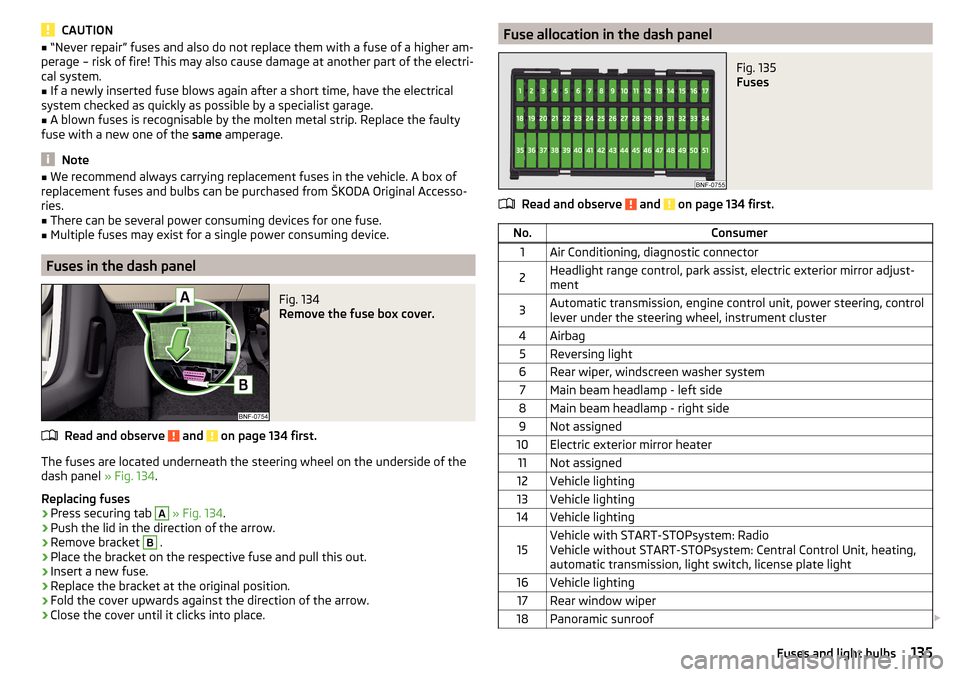
Fuse allocation in the dash panelFig. 135
Fuses
Read and observe and on page 134 first.
No.Consumer1Air Conditioning, diagnostic connector2Headlight range control, park assist, electric exterior mirror adjust-
ment3Automatic transmission, engine control unit, power steering, control
lever under the steering wheel, instrument cluster4Airbag5Reversing light6Rear wiper, windscreen washer system7Main beam headlamp - left side8Main beam headlamp - right side9Not assigned10Electric exterior mirror heater11Not assigned12Vehicle lighting13Vehicle lighting14Vehicle lighting15Vehicle with START-STOPsystem: Radio
Vehicle without START-STOPsystem: Central Control Unit, heating,
automatic transmission, light switch, license plate light16Vehicle lighting17Rear window wiper18Panoramic sunroof 135Fuses and light bulbs
Page 138 of 160

No.Consumer19Central locking system20Rear window heater21Reversing light22Horn23Voltage transformer24Headlamp flasher25Windscreen wipers26Radio27Turn signal lights, brake lights28Selector lever for the automatic transmission29Fuel pump30Engine control unit, instrument cluster, central control unit, rain sen-
sor, control lever under the steering wheel, diagnostic connector31Vehicle lighting32Central control unit33Vehicle lighting34Indoor lighting35Vehicle lighting36Vehicle lighting37ESC38Key bar39Lever under the steering wheel, windscreen washer system40Engine components41Brake pedal switch, cooling fan42Engine control unit43Fuel pump44Engine components45Engine components4612-volt power socket47Air blower for air conditioning/heating48Seat heaters49Electric power windowsNo.Consumer50Vehicle lighting51Electric power windows
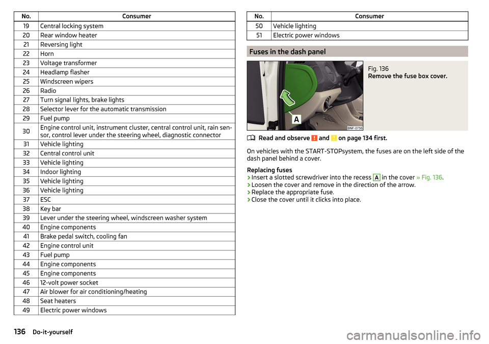
Fuses in the dash panel
Fig. 136
Remove the fuse box cover.
Read and observe and on page 134 first.
On vehicles with the START-STOPsystem, the fuses are on the left side of the
dash panel behind a cover.
Replacing fuses
›
Insert a slotted screwdriver into the recess
A
in the cover » Fig. 136.
›
Loosen the cover and remove in the direction of the arrow.
›
Replace the appropriate fuse.
›
Close the cover until it clicks into place.
136Do-it-yourself
Page 139 of 160

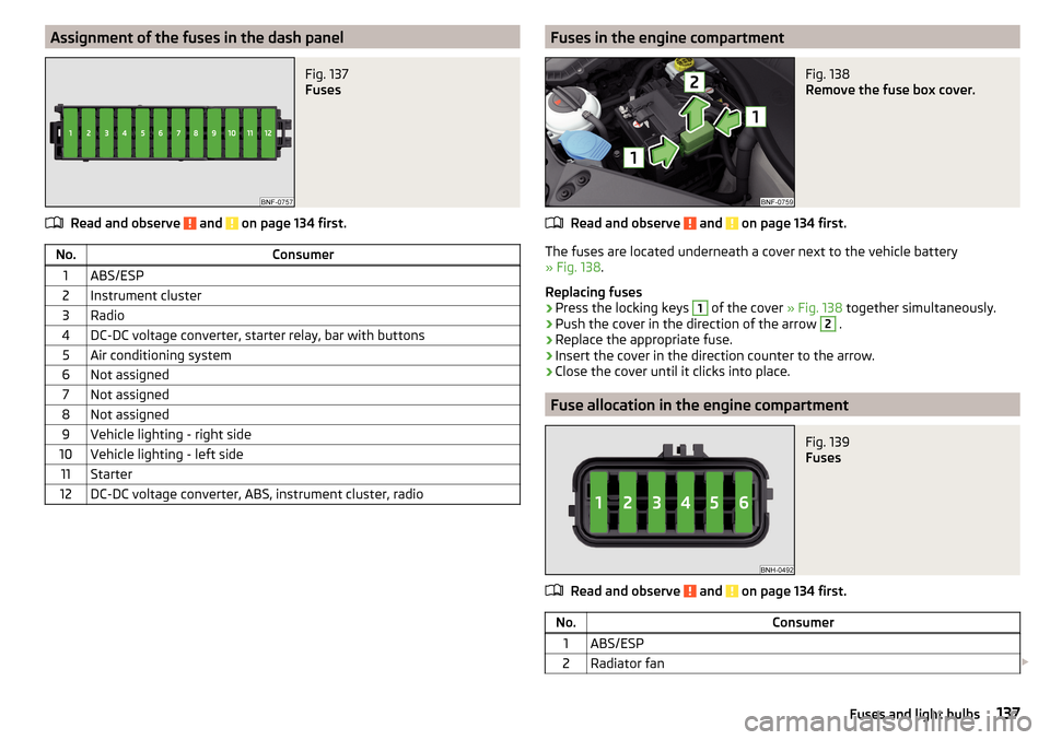
Assignment of the fuses in the dash panelFig. 137
Fuses
Read and observe and on page 134 first.
No.Consumer1ABS/ESP2Instrument cluster3Radio4DC-DC voltage converter, starter relay, bar with buttons5Air conditioning system6Not assigned7Not assigned8Not assigned9Vehicle lighting - right side10Vehicle lighting - left side11Starter12DC-DC voltage converter, ABS, instrument cluster, radioFuses in the engine compartmentFig. 138
Remove the fuse box cover.
Read and observe and on page 134 first.
The fuses are located underneath a cover next to the vehicle battery
» Fig. 138 .
Replacing fuses
›
Press the locking keys
1
of the cover » Fig. 138 together simultaneously.
›
Push the cover in the direction of the arrow
2
.
›
Replace the appropriate fuse.
›
Insert the cover in the direction counter to the arrow.
›
Close the cover until it clicks into place.
Fuse allocation in the engine compartment
Fig. 139
Fuses
Read and observe and on page 134 first.
No.Consumer1ABS/ESP2Radiator fan 137Fuses and light bulbs