air SKODA FABIA 2000 1.G / 6Y Owner's Manual
[x] Cancel search | Manufacturer: SKODA, Model Year: 2000, Model line: FABIA, Model: SKODA FABIA 2000 1.G / 6YPages: 86, PDF Size: 3.58 MB
Page 37 of 86
Downloaded from www.Manualslib.com manuals search engine FABIA 2000➤Inspection and Maintenance
EnginesEdition 09.04
S00.5301.14.2002-3 page 17 02
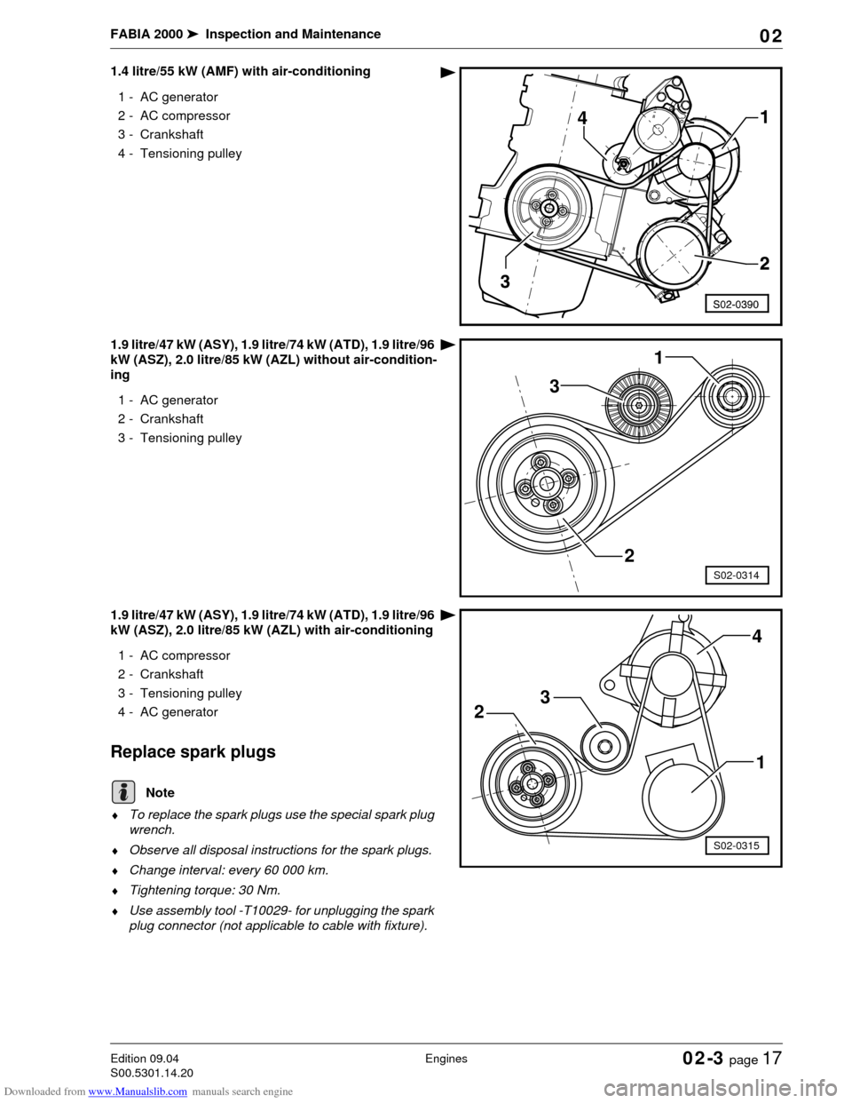
1.4 litre/55 kW (AMF) with air-conditioning
1 - AC generator
2- AC compressor
3 - Crankshaft
4 - Tensioning pulley
1.9 litre/47 kW (ASY), 1.9 litre/74 kW (ATD), 1.9 litre/96
kW (ASZ), 2.0 litre/85 kW (AZL) without air-condition-
ing
1 - AC generator
2 - Crankshaft
3 - Tensioning pulley
1.9 litre/47 kW (ASY), 1.9 litre/74 kW (ATD), 1.9 litre/96
kW (ASZ), 2.0 litre/85 kW (AZL) with air-conditioning
1- AC compressor
2 - Crankshaft
3 - Tensioning pulley
4 - AC generator
Replace spark plugs
♦To replace the spark plugs use the special spark plug
wrench.
♦Observe all disposal instructions for the spark plugs.
♦Change interval: every 60 000 km.
♦Tightening torque: 30 Nm.
♦Use assembly tool -T10029- for unplugging the spark
plug connector (not applicable to cable with fixture).
2
S02-0314
1
3
4
S02-0315
1 23
Note
Page 38 of 86
Downloaded from www.Manualslib.com manuals search engine FABIA 2000➤Inspection and Maintenance
EnginesEdition 09.04
S00.5301.14.2002-3 page 18 02
Replace air filter element
–Open the filter housing.
–Replace the filter element and clean the filter housing.
–Close filter housing and check correct fitting.
Replacing the fuel filter (diesel engine)
♦Make sure no diesel fuel comes into contact with the
coolant hoses. If necessary clean the hoses immedi-
ately!
♦It is absolutely necessary to observe the oil disposal
instructions!
♦Observe the disposal instructions!
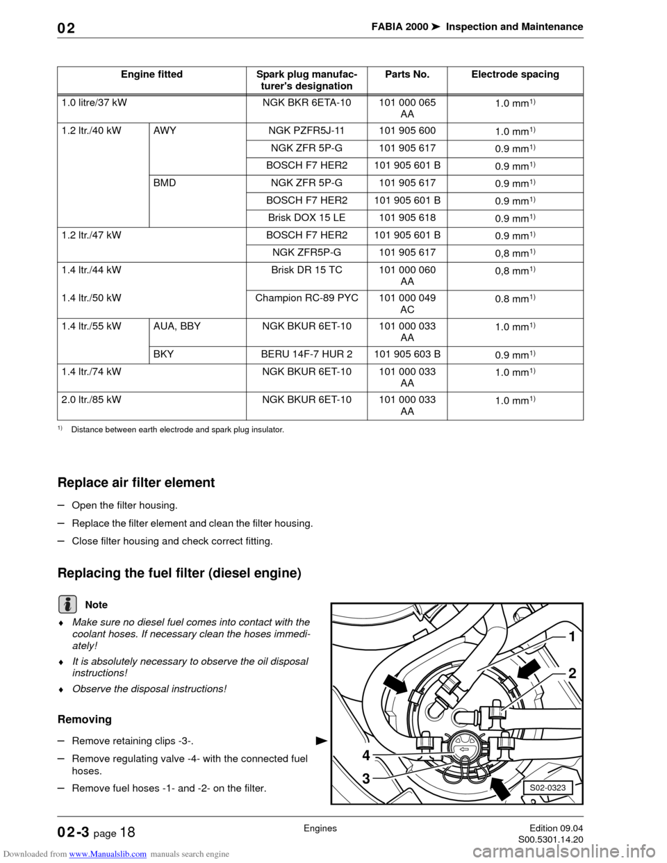
Removing
–Remove retaining clips -3-.
–Remove regulating valve -4- with the connected fuel
hoses.
–Remove fuel hoses -1- and -2- on the filter.Engine fitted Spark plug manufac-
turer's designationParts No. Electrode spacing
1.0 litre/37 kW NGK BKR 6ETA-10 101 000 065
AA1.0 mm
1)
1) Distance between earth electrode and spark plug insulator.
1.2 ltr./40 kW AWY NGK PZFR5J-11 101 905 600
1.0 mm1)
NGK ZFR 5P-G 101 905 617
0.9 mm1)
BOSCH F7 HER2 101 905 601 B
0.9 mm1)
BMD NGK ZFR 5P-G 101 905 617
0.9 mm1)
BOSCH F7 HER2 101 905 601 B
0.9 mm1)
Brisk DOX 15 LE 101 905 618
0.9 mm1)
1.2 ltr./47 kW BOSCH F7 HER2 101 905 601 B
0.9 mm1)
NGK ZFR5P-G 101 905 617
0,8 mm1)
1.4 ltr./44 kW Brisk DR 15 TC 101 000 060
AA0,8 mm1)
1.4 ltr./50 kW Champion RC-89 PYC 101 000 049
AC0.8 mm1)
1.4 ltr./55 kW AUA, BBY NGK BKUR 6ET-10 101 000 033
AA1.0 mm1)
BKY BERU 14F-7 HUR 2 101 905 603 B
0.9 mm1)
1.4 ltr./74 kW NGK BKUR 6ET-10 101 000 033
AA1.0 mm1)
2.0 ltr./85 kW NGK BKUR 6ET-10 101 000 033
AA1.0 mm1)
Note
1
2
3
4
S02-0323
Page 44 of 86
Downloaded from www.Manualslib.com manuals search engine FABIA 2000➤Inspection and Maintenance
GearboxEdition 07.03
S00.5301.12.2002-4 page 4 02
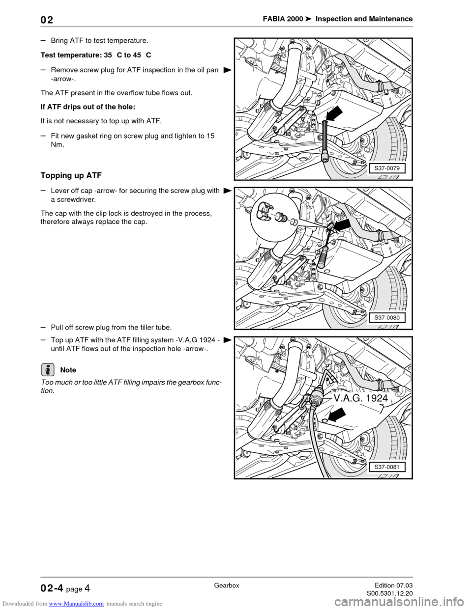
–Bring ATF to test temperature.
Test temperature: 35 C to 45 C
–Remove screw plug for ATF inspection in the oil pan
-arrow-.
The ATF present in the overflow tube flows out.
If ATF drips out of the hole:
It is not necessary to top up with ATF.
–Fit new gasket ring on screw plug and tighten to 15
Nm.
Topping up ATF
–Lever off cap -arrow- for securing the screw plug with
a screwdriver.
The cap with the clip lock is destroyed in the process,
therefore always replace the cap.
–Pull off screw plug from the filler tube.
–Top up ATF with the ATF filling system -V.A.G 1924 -
until ATF flows out of the inspection hole -arrow-.
Too much or too little ATF filling impairs the gearbox func-
tion.
S37-0079
S37-0080
V.A.G. 1924
S37-0081
Note
Page 47 of 86
Downloaded from www.Manualslib.com manuals search engine FABIA 2000➤Inspection and Maintenance
ChassisEdition 02.04
S00.5301.13.2002-5 page 1 02
02-5 Chassis
Inspecting thickness of front and rear
brake pads/linings
Front disc brake pads:
For a better assessment of the residual pad thickness re-
move wheels. Do not mix up wheels (mark).
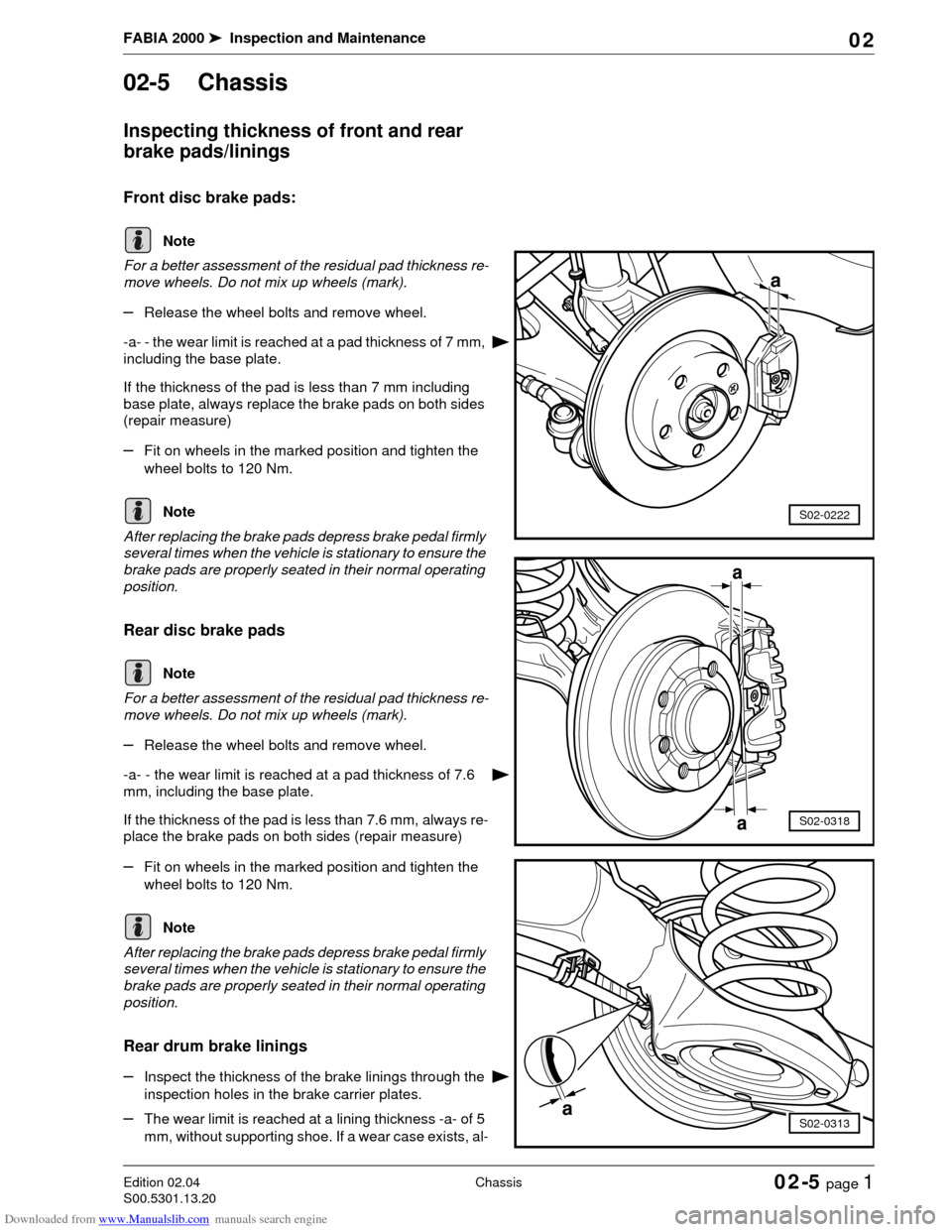
–Release the wheel bolts and remove wheel.
-a- - the wear limit is reached at a pad thickness of 7 mm,
including the base plate.
If the thickness of the pad is less than 7 mm including
base plate, always replace the brake pads on both sides
(repair measure)
–Fit on wheels in the marked position and tighten the
wheel bolts to 120 Nm.
After replacing the brake pads depress brake pedal firmly
several times when the vehicle is stationary to ensure the
brake pads are properly seated in their normal operating
position.
Rear disc brake pads
For a better assessment of the residual pad thickness re-
move wheels. Do not mix up wheels (mark).
–Release the wheel bolts and remove wheel.
-a- - the wear limit is reached at a pad thickness of 7.6
mm, including the base plate.
If the thickness of the pad is less than 7.6 mm, always re-
place the brake pads on both sides (repair measure)
–Fit on wheels in the marked position and tighten the
wheel bolts to 120 Nm.
After replacing the brake pads depress brake pedal firmly
several times when the vehicle is stationary to ensure the
brake pads are properly seated in their normal operating
position.
Rear drum brake linings
–Inspect the thickness of the brake linings through the
inspection holes in the brake carrier plates.
–The wear limit is reached at a lining thickness -a- of 5
mm, without supporting shoe. If a wear case exists, al-
Note
a
S02-0222Note
Note
S02-0318
a
a
Note
S02-0313a
Page 48 of 86
Downloaded from www.Manualslib.com manuals search engine FABIA 2000➤Inspection and Maintenance
ChassisEdition 02.04
S00.5301.13.2002-5 page 2 02
ways replace the brake linings on both sides (repair
measure).
Avoid soiling from brake fluid or grease flowing out.
Inspecting brake system for leaks and
damage
–Inspect master brake cylinder, brake servo unit (for
ABS: hydraulic unit), brake pressure regulator, brake
calipers for leaks and damage.
–Inspect brake hoses for twisting.
–Ensure that the brake hoses do not touch any parts of
the vehicle when the steering is turned to full left or full
right lock.
–Inspect the brake hoses for porous and brittle points.
Inspect the brake hoses and brake lines for chafing
points.
–Inspect the brake connections and attachments to en-
sure they are correctly fitted, free of leaks and corro-
sion.
Changing brake fluid (every 2 years)
Special tools, test and measuring equipment and
auxiliary items required
♦Extraction device
♦Brake pedal support, e.g. - V.A.G 1869/2-
Use only fresh genuine brake fluid FMVSS 571.116 DOT
4.
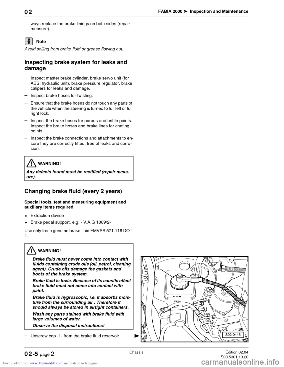
–Unscrew cap -1- from the brake fluid reservoir
Note
WARNING!
Any defects found must be rectified (repair meas-
ure).
WARNING!
Brake fluid must never come into contact with
fluids containing crude oils (oil, petrol, cleaning
agent). Crude oils damage the gaskets and
boots of the brake system.
Brake fluid is toxic. Because of its caustic effect
brake fluid must not come into contact with
paint.
Brake fluid is hygroscopic, i.e. it absorbs mois-
ture from the surrounding air . Therefore it
should always be stored in airtight containers.
Wash any parts stained with brake fluid with
large volumes of water.
Observe the disposal instructions!
Page 50 of 86
Downloaded from www.Manualslib.com manuals search engine FABIA 2000➤Inspection and Maintenance
ChassisEdition 02.04
S00.5301.13.2002-5 page 4 02
–Repeat the procedure for all wheels in the following
sequence: rear left, front right and front left.
1)
–Insert strainer in the brake fluid reservoir and fill with
brake fluid up to the specified level.
–Inspect pedal position and idle travel at brake pedal.
Idle travel: max. 1/3 of pedal travel.
Vehicles with ABS or ABS/EDL:
A road test on such models must be carried out after
bleeding the brake system. While doing so perform at
least one ABS adjustment!
Inspecting the brake fluid level
Use only fresh genuine brake fluid FMVSS 571.116 DOT
4.
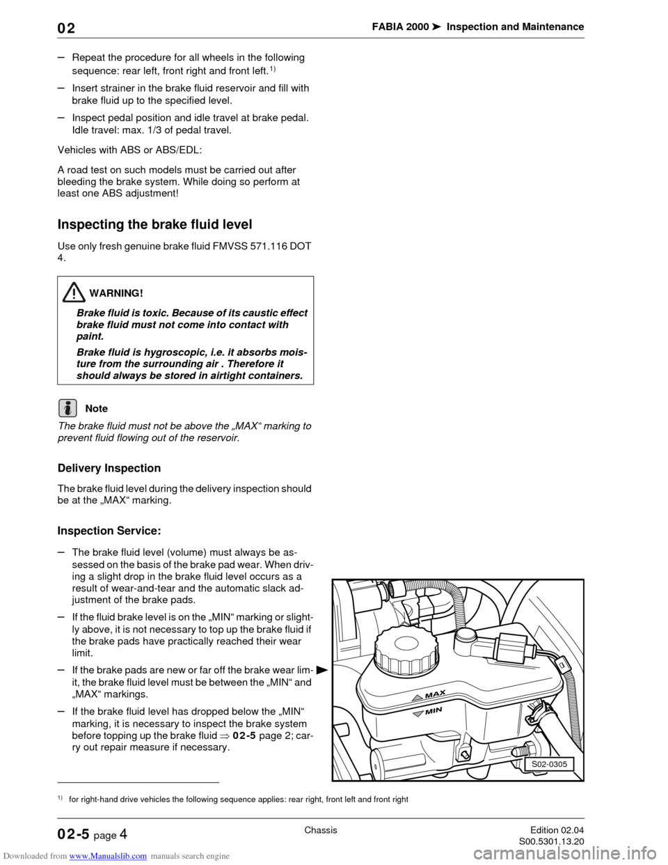
The brake fluid must not be above the „MAX“ marking to
prevent fluid flowing out of the reservoir.
Delivery Inspection
The brake fluid level during the delivery inspection should
be at the „MAX“ marking.
Inspection Service:
–The brake fluid level (volume) must always be as-
sessed on the basis of the brake pad wear. When driv-
ing a slight drop in the brake fluid level occurs as a
result of wear-and-tear and the automatic slack ad-
justment of the brake pads.
–If the fluid brake level is on the „MIN“ marking or slight-
ly above, it is not necessary to top up the brake fluid if
the brake pads have practically reached their wear
limit.
–If the brake pads are new or far off the brake wear lim-
it, the brake fluid level must be between the „MIN“ and
„MAX“ markings.
–If the brake fluid level has dropped below the „MIN“
marking, it is necessary to inspect the brake system
before topping up the brake fluid ⇒02-5 page 2; car-
ry out repair measure if necessary.
1)for right-hand drive vehicles the following sequence applies: rear right, front left and front right
WARNING!
Brake fluid is toxic. Because of its caustic effect
brake fluid must not come into contact with
paint.
Brake fluid is hygroscopic, i.e. it absorbs mois-
ture from the surrounding air . Therefore it
should always be stored in airtight containers.
Note
S02-0305
Page 51 of 86
Downloaded from www.Manualslib.com manuals search engine FABIA 2000➤Inspection and Maintenance
ChassisEdition 02.04
S00.5301.13.2002-5 page 5 02
Track rod ends: Inspect play, correct at-
tachment and joint boots
–Raise vehicle (wheel clear of the ground) and inspect
play by moving the track rods and wheels. Clearance:
There must not be any play present.
–Inspect attachment.
–Inspect seals for damage and correct installation.
Inspecting tyres (including spare wheel)
Only tyres of the same type may be fitted to the vehicle.
Tyres of the same brand and tread pattern must always
be fitted to wheels on the same axle!
Delivery Inspection:
–Inspect the tyre tread and side wall for damage, if nec-
essary remove any foreign bodies from the tyres, such
as nails or glass splinters.
Inspection Service:
–Inspect the tyre tread and side wall for damage, if nec-
essary remove any foreign bodies from the tyres, such
as nails or glass splinters.
–Inspect tyres for scrubbing, tread worn down on one
side, porous side walls, cuts and punctures. Any de-
fects found must be advised to the customer and the
customer's attention must be drawn to any necessary
repair measures!
Inspecting tyre wear
–The wear pattern on the front tyres makes it possible
to assess whether it is necessary to inspect the wheel
toe and camber:
♦The formation of ridges on the tyre tread is an indica-
tion of wheel toe errors.
♦Tread worn on one side is usually attributable to cam-
ber errors.
–If such signs of wear are found, determine the cause
by checking the chassis alignment (repair measure).
Note
WARNING!
Tyres that are more than 6 years old must only be
used in case of emergency and while driving very
carefully.
Page 52 of 86
Downloaded from www.Manualslib.com manuals search engine FABIA 2000➤Inspection and Maintenance
ChassisEdition 02.04
S00.5301.13.2002-5 page 6 02
Inspecting the tyre tread depth (includ-
ing spare wheel) and entering
This value may differ in individual countries as a result of
differing statutory requirements.
If the tyre tread depth is close to the legal minimum, in
other words if no further tread exists at the points around
the circumference of the tyre at which the 1.6 mm high
wear indicators are positioned, the customer should be
informed of the necessary repair measures.
Tightening wheel bolts to specific torque
Special tools, test and measuring equipment and
auxiliary items required
♦Torque wrench
Tightening torque for steel and light alloy wheels 120 Nm.
Inspecting the tyre inflation pressure (in-
cluding spare wheel) and correcting the
tyre inflation pressure if necessary
Special tools, test and measuring equipment and
auxiliary items required
♦Tyre inflation pressure tester
♦The tyre inflation pressures are indicated on a stick-
er,which is affixed to the inside of the fuel filler flap.
♦The tyre inflation pressures indicated on the sticker
apply only to the tyres when cold. Do not reduce the
higher inflation pressure of warm tyres.
♦If winter tyres are fitted, the relevant tyre inflation pres-
sure should be increased by 0.2 bar/20 kPa.
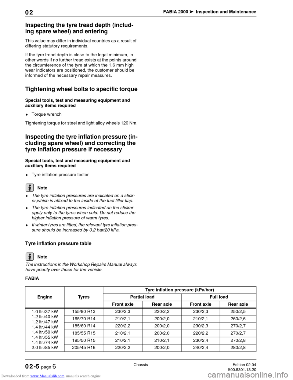
Tyre inflation pressure table
The instructions in the Workshop Repairs Manual always
have priority over those for the vehicle.
FABIA
Note
Note
Engine TyresTyre inflation pressure (kPa/bar)
Partial load Full load
Front axle Rear axle Front axle Rear axle
1.0 ltr./37 kW
1.2 ltr./40 kW
1.2 ltr./47 kW
1.4 ltr./44 kW
1.4 ltr./50 kW
1.4 ltr./55 kW
1.4 ltr./74 kW
2.0 ltr./85 kW155/80 R13 230/2,3 220/2,2 230/2,3 250/2,5
165/70 R14 210/2,1 200/2,0 210/2,1 260/2,6
185/60 R14 220/2,2 200/2,0 230/2,3 270/2,7
185/55 R15 210/2,1 200/2,0 220/2,2 270/2,7
195/50 R15 210/2,1 210/2,1 230/2,4 270/2,8
205/45 R16 220/2,2 200/2,0 240/2,4 280/2,8
Page 55 of 86

Downloaded from www.Manualslib.com manuals search engine FABIA 2000➤Inspection and Maintenance
Electrical SystemEdition 09.04
S00.5301.14.2002-6 page 1 02
02-6 Electrical System
Power windows: Inspecting positioning
If the battery is diconnected the power windows forget
their current position.
Test conditions:
•All car doors closed
The inspection procedure is carried out from the outside
Close window with the car key using the convenience
closing system.
–Turn car key into close position and hold until all the
windows are closed.
–After closing the windows hold the key in the close po-
sition for approximately another 3 seconds.
Electrical components: Check for proper
operation
–Inspect lighting, main headlights, headlight beam con-
trol, fog lights, turn signal lights, hazard warning light
system, tail lights, rear fog lights, reversing lights,
brake lights, parking light control for brightness and
proper operation.
–Inspect interior lights, illuminated storage compart-
ment, illuminated ashtray for proper operation.
–Airbag warning lamps: Check operation ⇒Chapter
02-7.
–Inspect warning buzzer, onboard computer, all switch-
es in centre console as well as on the dash panel and
horn for proper operation.
–Inspect power windows, exterior mirrors (heated and
electrically adjustable), central locking system, infra-
red remote control and convenience closing system
for proper operation
–Inspect heating of front seats for proper operation.
–Inspect radio for proper reception and absence of in-
terference, also inspect speakers ⇒02-6 page 2.
Battery: Testing no-load voltage
Special tools, test and measuring equipment and
auxiliary items required
♦Multimeter (e.g. -V.A.G 1526 A-)
Prior to the measurement the vehicle must have been in
the no-load state for at least two hours (no engine starts,
no charging or discharging of battery).
The following procedure applies to measuring the battery
voltage in the no-load state (after at least two hours):
–With the battery installed measure the voltage be-
tween the terminals (ignition switched off).
Page 56 of 86
Downloaded from www.Manualslib.com manuals search engine FABIA 2000➤Inspection and Maintenance
Electrical SystemEdition 09.04
S00.5301.14.2002-6 page 2 02
If the tester indicates a voltage of 12.5 Volts or more, the
battery is O.K.
If the voltage is less than 12.5 Volts determine the cause
(repair measure).
Battery: Inspecting electrolyte level, top-
ping up with distilled water if necessary
This procedure is not valid for batteries with the sign
„Magic eye“. Test procedure for these batteries
⇒Electrical System; Rep. Gr. 27.
–Inspect electrolyte level:
–The electrolyte level must be between the „MIN“ and
„MAX“ markings.
–Top up the battery with distilled water up to the „MAX“
marking if necessary.
Before disconnecting the battery determine the code of
radio sets fitted with anti-theft coding.
Radio: Check for proper operation
Precise information on how to operate the radio should
be obtained from the operating instructions before in-
specting proper operation of the radio set.
–Switch radio set on and off.
–Operate the volume control.
–Carry out station programming1).
–Inspect station search1).
–Inspect cassette player (insert cassette and play) 1).
–Inspect activation of the anti-theft code of the radio 1).
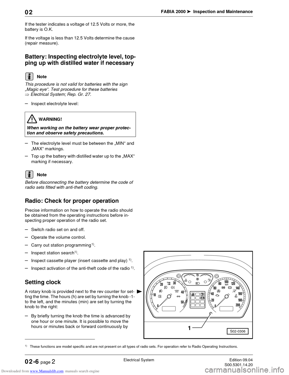
Setting clock
A rotary knob is provided next to the rev counter for set-
ting the time. The hours (h) are set by turning the knob -1-
to the left, and the minutes (min) are set by turning the
knob to the right:
–By briefly turning the knob the time is advanced by
one hour or one minute. It is possible to move the
hours or minutes back or forward continuously by
Note
WARNING!
When working on the battery wear proper protec-
tion and observe safety precautions.
1)These functions are model specific and are not present on all types of radio sets. For operation refer to Radio Operating Instructions.
Note
S02-03061