air SKODA FABIA 2000 1.G / 6Y Owner's Guide
[x] Cancel search | Manufacturer: SKODA, Model Year: 2000, Model line: FABIA, Model: SKODA FABIA 2000 1.G / 6YPages: 86, PDF Size: 3.58 MB
Page 58 of 86
Downloaded from www.Manualslib.com manuals search engine FABIA 2000➤Inspection and Maintenance
Electrical SystemEdition 09.04
S00.5301.14.2002-6 page 4 02
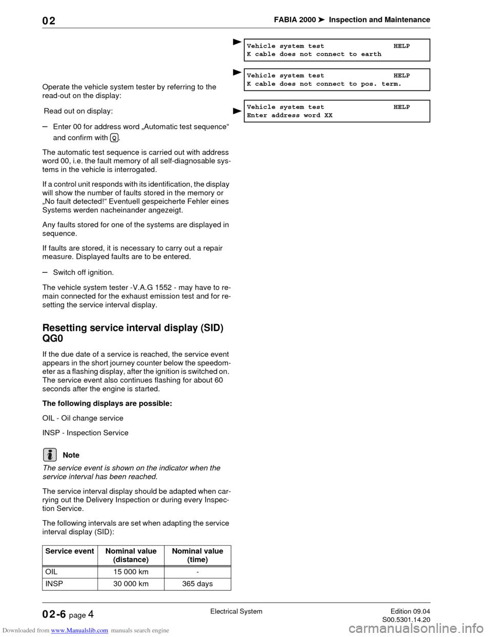
Operate the vehicle system tester by referring to the
read-out on the display:
Read out on display:
–Enter 00 for address word „Automatic test sequence“
and confirm with .
The automatic test sequence is carried out with address
word 00, i.e. the fault memory of all self-diagnosable sys-
tems in the vehicle is interrogated.
If a control unit responds with its identification, the display
will show the number of faults stored in the memory or
„No fault detected!“ Eventuell gespeicherte Fehler eines
Systems werden nacheinander angezeigt.
Any faults stored for one of the systems are displayed in
sequence.
If faults are stored, it is necessary to carry out a repair
measure. Displayed faults are to be entered.
–Switch off ignition.
The vehicle system tester -V.A.G 1552 - may have to re-
main connected for the exhaust emission test and for re-
setting the service interval display.
Resetting service interval display (SID)
QG0
If the due date of a service is reached, the service event
appears in the short journey counter below the speedom-
eter as a flashing display, after the ignition is switched on.
The service event also continues flashing for about 60
seconds after the engine is started.
The following displays are possible:
OIL - Oil change service
INSP - Inspection Service
The service event is shown on the indicator when the
service interval has been reached.
The service interval display should be adapted when car-
rying out the Delivery Inspection or during every Inspec-
tion Service.
The following intervals are set when adapting the service
interval display (SID):
Vehicle system test HELP
K cable does not connect to earth
Vehicle system test HELP
K cable does not connect to pos. term.
Vehicle system test HELP
Enter address word XX
Q
Note
Service event Nominal value
(distance)Nominal value
(time)
OIL 15 000 km -
INSP 30 000 km 365 days
Page 69 of 86
Downloaded from www.Manualslib.com manuals search engine FABIA 2000➤Inspection and Maintenance
BodyEdition 09.04
S00.5301.14.2002-7 page 1 02
02-7 Body
Airbag units: Visual inspection
Inspecting operation of airbag unit
When the ignition is switched on the airbag warning lamp
K75 lights up for approximately 4 seconds. Should the
warning lamp flash again for a further 12 seconds this is
an indication that the front passenger airbag or the side
airbag unit on the front passenger is electronically locked
(valid for vehicles which do not have an airbag switch-off
function).
The warning lamp will go out after 4 seconds for vehicles
which are fitted with an airbag switch-off function and
switching off of the front passenger airbag will be sig-
nalled by the warning lamp „AIRBAG OFF“ in the middle
of the dash panel.
♦If warning lamp K75 does not go out after 4 seconds
and lights up continously there is a fault.
♦If the warning lamp goes out and then lights up again
the control unit is not coded, the wrong control unit has
been fitted or there is a fault.
♦If the airbag warning light K75 flashes constantly, it is
then necessary to replace the airbag control unit J234.
If the warning light indicates a fault, the fault must be
rectified (repair measure) Body Work; Rep. Gr. 01.
Inspecting airbag for external damage
Driver and front passenger airbag units
The logo „AIRBAG“ on the padded boss of the steering
wheel (driver's side) and on the right side of the dash pan-
el (passenger side) indicates that an airbag is fitted.
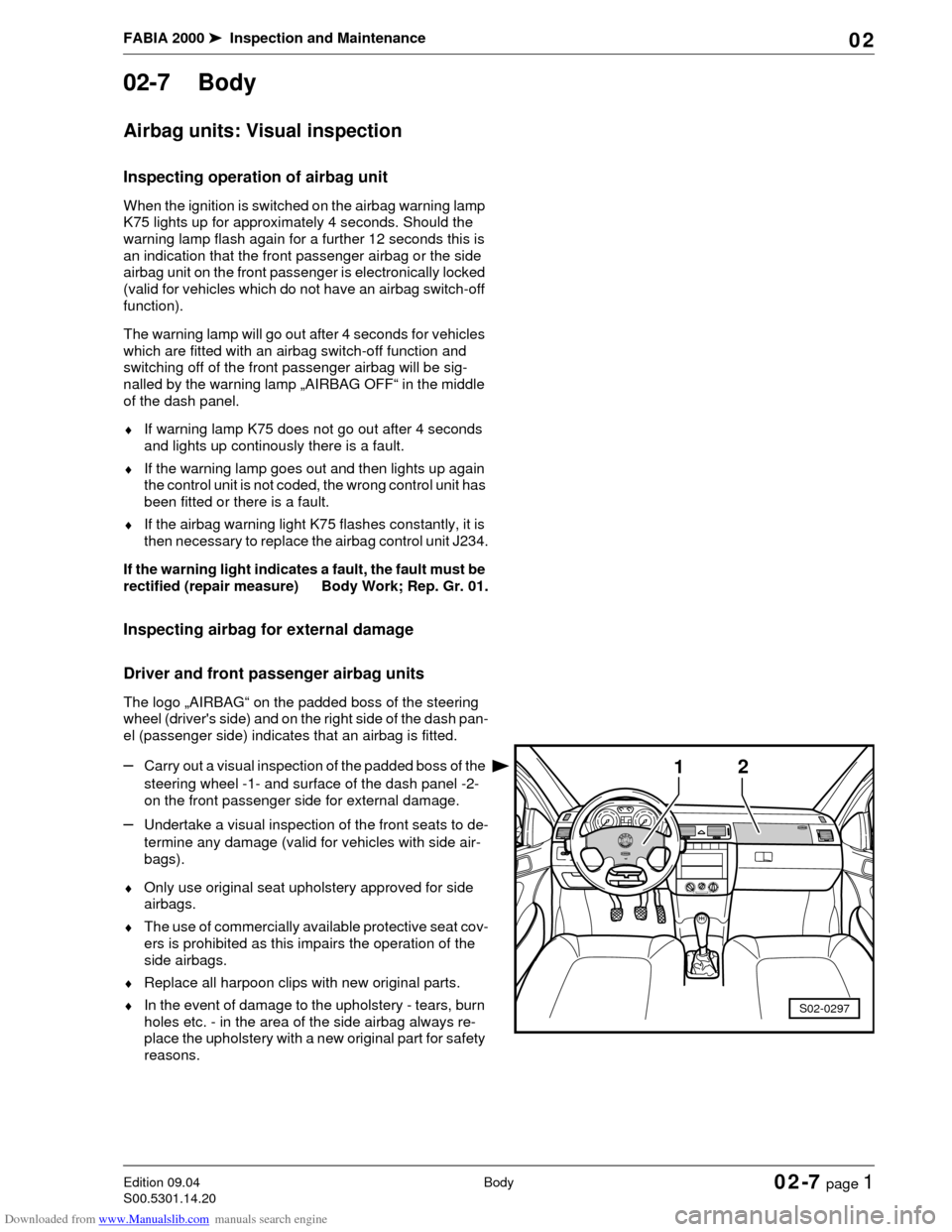
–Carry out a visual inspection of the padded boss of the
steering wheel -1- and surface of the dash panel -2-
on the front passenger side for external damage.
–Undertake a visual inspection of the front seats to de-
termine any damage (valid for vehicles with side air-
bags).
♦Only use original seat upholstery approved for side
airbags.
♦The use of commercially available protective seat cov-
ers is prohibited as this impairs the operation of the
side airbags.
♦Replace all harpoon clips with new original parts.
♦In the event of damage to the upholstery - tears, burn
holes etc. - in the area of the side airbag always re-
place the upholstery with a new original part for safety
reasons.
1
S02-0297
2
Page 70 of 86
Downloaded from www.Manualslib.com manuals search engine FABIA 2000➤Inspection and Maintenance
BodyEdition 09.04
S00.5301.14.2002-7 page 2 02
Do not affix any stickers or cover over the padded boss of
the steering wheel -1- and the foam-lined surface of the
airbag unit on the front passenger side -2- or do not carry
out any modifications to these parts. These parts must
only be cleaned with a dry and slightly moistened cloth.
Inspect key switch for deactivation of
front passenger airbag
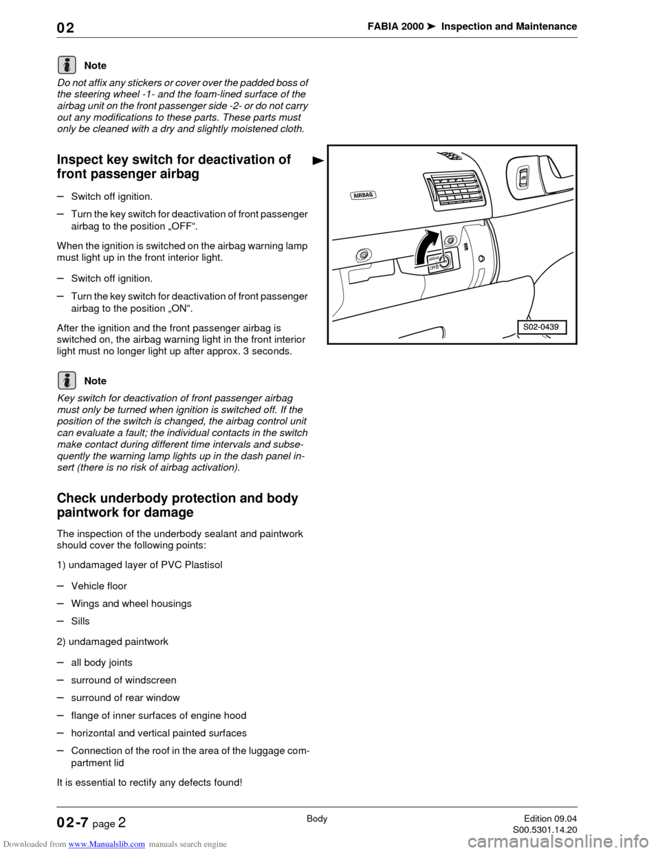
–Switch off ignition.
–Turn the key switch for deactivation of front passenger
airbag to the position „OFF“.
When the ignition is switched on the airbag warning lamp
must light up in the front interior light.
–Switch off ignition.
–Turn the key switch for deactivation of front passenger
airbag to the position „ON“.
After the ignition and the front passenger airbag is
switched on, the airbag warning light in the front interior
light must no longer light up after approx. 3 seconds.
Key switch for deactivation of front passenger airbag
must only be turned when ignition is switched off. If the
position of the switch is changed, the airbag control unit
can evaluate a fault; the individual contacts in the switch
make contact during different time intervals and subse-
quently the warning lamp lights up in the dash panel in-
sert (there is no risk of airbag activation).
Check underbody protection and body
paintwork for damage
The inspection of the underbody sealant and paintwork
should cover the following points:
1) undamaged layer of PVC Plastisol
–Vehicle floor
–Wings and wheel housings
–Sills
2) undamaged paintwork
–all body joints
–surround of windscreen
–surround of rear window
–flange of inner surfaces of engine hood
–horizontal and vertical painted surfaces
–Connection of the roof in the area of the luggage com-
partment lid
It is essential to rectify any defects found!
Note
Note
Page 71 of 86
Downloaded from www.Manualslib.com manuals search engine FABIA 2000➤Inspection and Maintenance
BodyEdition 09.04
S00.5301.14.2002-7 page 3 02
The materials and the corresponding work instructions
are listed in the ⇒Technical Service Handbook, Part 6 -
Technology of paint repairs, chemical materials.
Inspecting plenum chamber and water
drain openings for dirt, cleaning if neces-
sary
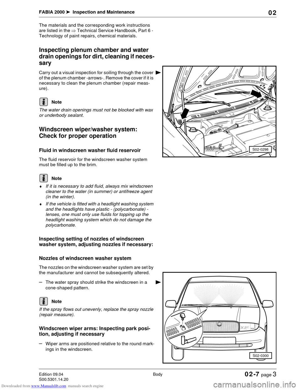
Carry out a visual inspection for soiling through the cover
of the plenum chamber -arrows-. Remove the cover if it is
necessary to clean the plenum chamber (repair meas-
ure).
The water drain openings must not be blocked with wax
or underbody sealant.
Windscreen wiper/washer system:
Check for proper operation
Fluid in windscreen washer fluid reservoir
The fluid reservoir for the windscreen washer system
must be filled up to the brim.
♦If it is necessary to add fluid, always mix windscreen
cleaner to the water (in summer) or antifreeze agent
(in the winter).
♦If the vehicle is fitted with a headlight washing system
and the headlights have plastic - (polycarbonate) -
lenses, one must only use fluids for topping up the
headlight washing system which do not damage the
polycarbonate.
Inspecting setting of nozzles of windscreen
washer system, adjusting nozzles if necessary:
Nozzles of windscreen washer system
The nozzles on the windscreen washer system are set by
the manufacturer and cannot be subsequently altered.
–The water spray should strike the windscreen in a
cone-shaped pattern.
If the spray flows out unevenly, replace the spray nozzle
(repair measure).
Windscreen wiper arms: Inspecting park posi-
tion, adjusting if necessary
–Wiper arms are positioned relative to the round mark-
ings in the windscreen.
S02-0298
Note
Note
S02-0300
Note
Page 72 of 86
Downloaded from www.Manualslib.com manuals search engine FABIA 2000➤Inspection and Maintenance
BodyEdition 09.04
S00.5301.14.2002-7 page 4 02
The specified tightening torque for the windscreen wiper
arms is 20 Nm.
Wiper arms of rear window: Inspecting park po-
sition, adjusting if necessary, spray nozzle of
rear window: Inspect setting and adjust if neces-
sary
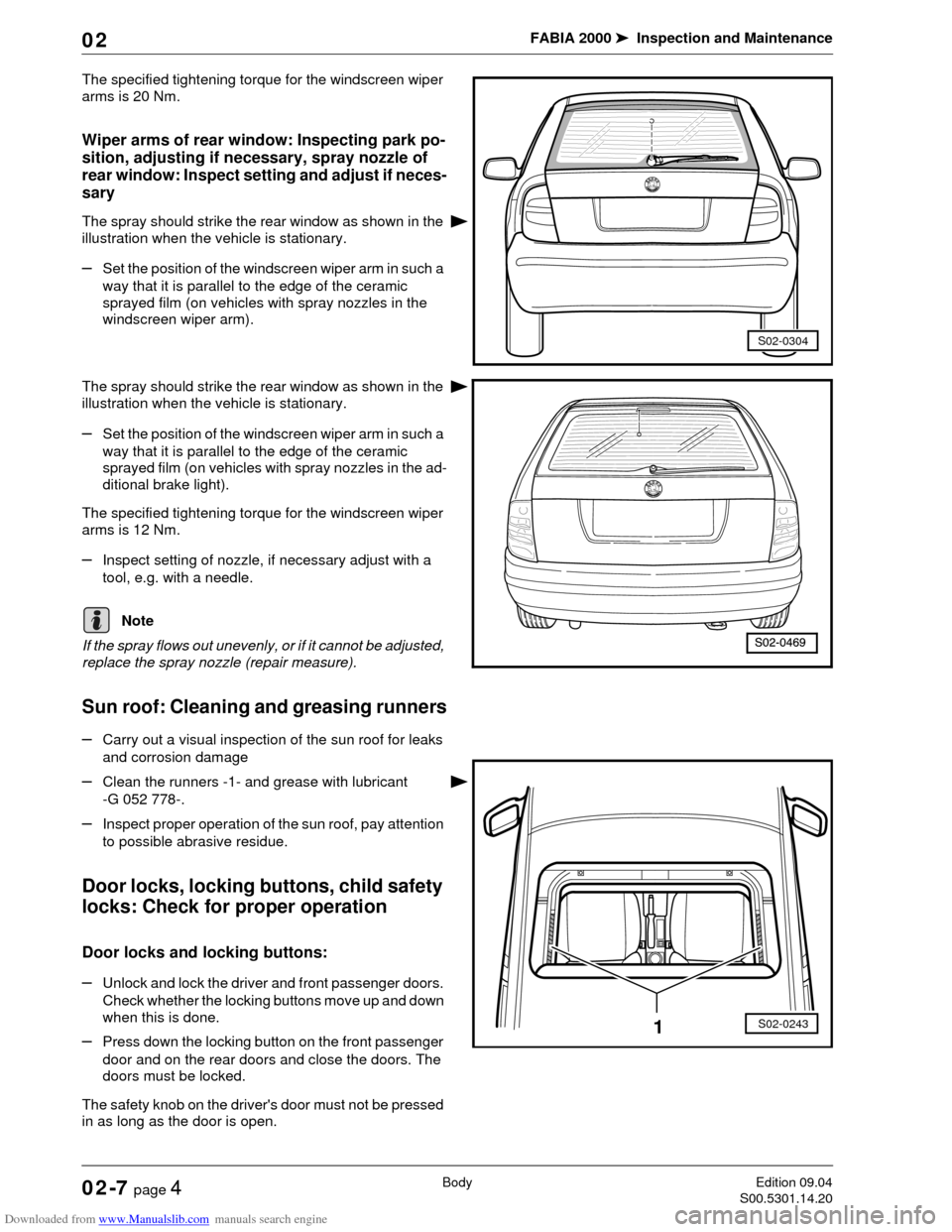
The spray should strike the rear window as shown in the
illustration when the vehicle is stationary.
–Set the position of the windscreen wiper arm in such a
way that it is parallel to the edge of the ceramic
sprayed film (on vehicles with spray nozzles in the
windscreen wiper arm).
The spray should strike the rear window as shown in the
illustration when the vehicle is stationary.
–Set the position of the windscreen wiper arm in such a
way that it is parallel to the edge of the ceramic
sprayed film (on vehicles with spray nozzles in the ad-
ditional brake light).
The specified tightening torque for the windscreen wiper
arms is 12 Nm.
–Inspect setting of nozzle, if necessary adjust with a
tool, e.g. with a needle.
If the spray flows out unevenly, or if it cannot be adjusted,
replace the spray nozzle (repair measure).
Sun roof: Cleaning and greasing runners
–Carry out a visual inspection of the sun roof for leaks
and corrosion damage
–Clean the runners -1- and grease with lubricant
-G 052 778-.
–Inspect proper operation of the sun roof, pay attention
to possible abrasive residue.
Door locks, locking buttons, child safety
locks: Check for proper operation
Door locks and locking buttons:
–Unlock and lock the driver and front passenger doors.
Check whether the locking buttons move up and down
when this is done.
–Press down the locking button on the front passenger
door and on the rear doors and close the doors. The
doors must be locked.
The safety knob on the driver's door must not be pressed
in as long as the door is open.
S02-0304
Note
S02-02431
Page 74 of 86
Downloaded from www.Manualslib.com manuals search engine FABIA 2000➤Inspection and Maintenance
BodyEdition 09.04
S00.5301.14.2002-7 page 6 02
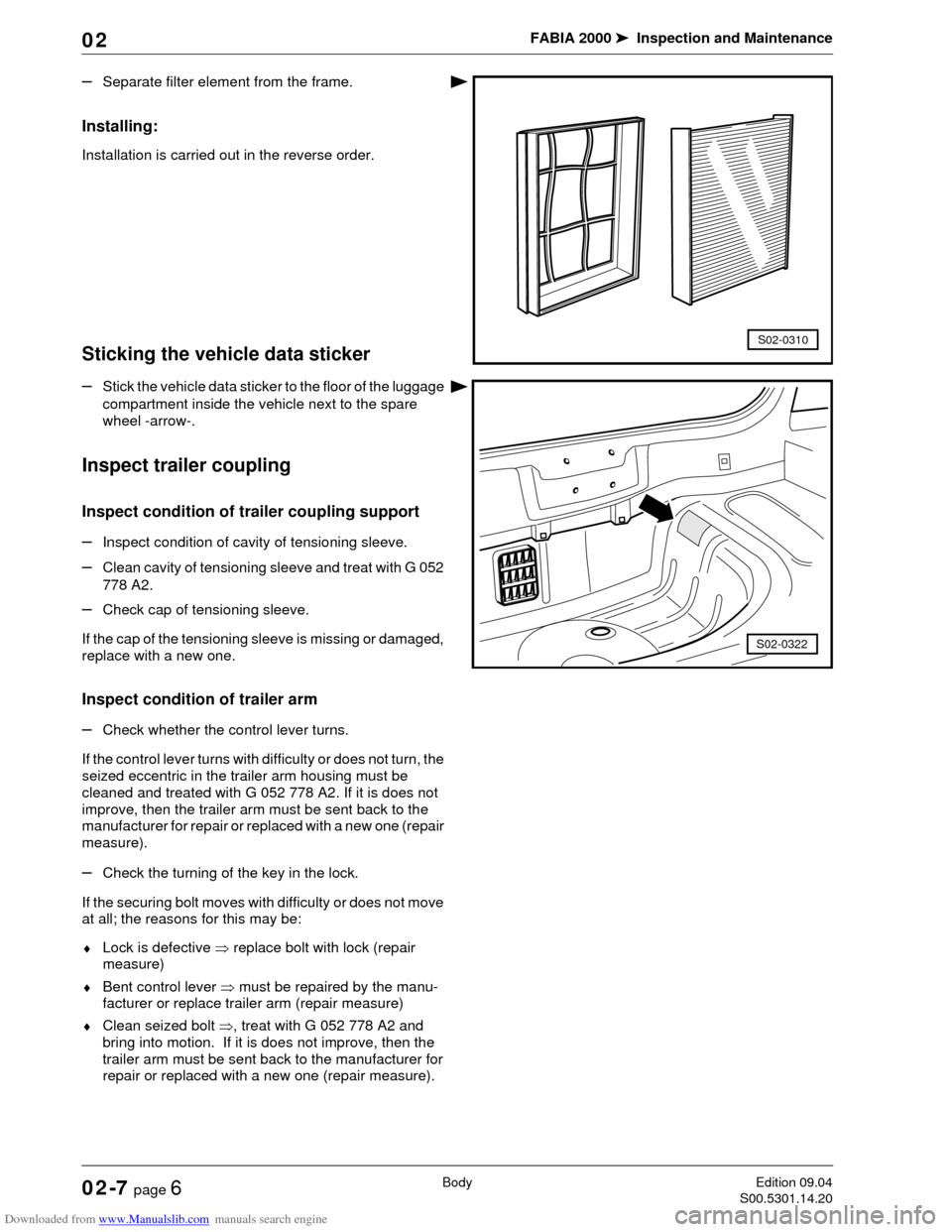
–Separate filter element from the frame.
Installing:
Installation is carried out in the reverse order.
Sticking the vehicle data sticker
–Stick the vehicle data sticker to the floor of the luggage
compartment inside the vehicle next to the spare
wheel -arrow-.
Inspect trailer coupling
Inspect condition of trailer coupling support
–Inspect condition of cavity of tensioning sleeve.
–Clean cavity of tensioning sleeve and treat with G 052
778 A2.
–Check cap of tensioning sleeve.
If the cap of the tensioning sleeve is missing or damaged,
replace with a new one.
Inspect condition of trailer arm
–Check whether the control lever turns.
If the control lever turns with difficulty or does not turn, the
seized eccentric in the trailer arm housing must be
cleaned and treated with G 052 778 A2. If it is does not
improve, then the trailer arm must be sent back to the
manufacturer for repair or replaced with a new one (repair
measure).
–Check the turning of the key in the lock.
If the securing bolt moves with difficulty or does not move
at all; the reasons for this may be:
♦Lock is defective ⇒ replace bolt with lock (repair
measure)
♦Bent control lever ⇒ must be repaired by the manu-
facturer or replace trailer arm (repair measure)
♦Clean seized bolt ⇒, treat with G 052 778 A2 and
bring into motion. If it is does not improve, then the
trailer arm must be sent back to the manufacturer for
repair or replaced with a new one (repair measure).
S02-0310
S02-0322
Page 75 of 86
Downloaded from www.Manualslib.com manuals search engine FABIA 2000➤Inspection and Maintenance
BodyEdition 09.04
S00.5301.14.2002-7 page 7 02
When applying G 052 778 A2 make sure that the product
does not penetrate into the gap between the lock bolt,
control lever, eccentric and trailer arm housing.
Trailer coupling: Check for proper operation
–Tighten trailer arm in the tensioning sleeve.
–Close lock and remove key.
–Check for correct closing by turning the control lever
downwards.
Note
WARNING!
If one of the measures cannot be carried out or if
the closed lever can be turned to an angle greater
than 5 , the trailer coupling is damaged and must
not be operated. The fault must be identified and
the damaged components must be replaced (repair
measure).
Page 77 of 86
Downloaded from www.Manualslib.com manuals search engine FABIA 2000➤Inspection and Maintenance
Exhaust-emission AnalysisEdition 09.04
S00.5301.14.2002-8 page 1 02
02-8 Exhaust-emission Analy-
sis
The exhaust-emission analysis must be carried out ac-
cording to the relevant national legislation of the particu-
lar country.
Exhaust-Emission Analysis on Models
with Fuel Engines
Perform the following visual inspections and comply with
the setting conditions below before performing the ex-
haust-emission analysis:
Visual inspection
♦Lambda probes are connected
♦All vacuum hoses are connected
♦All wires of the activated charcoal filter system are
connected
♦All the electrical wires of the ignition and injection sys-
tem are connected
♦Hose for crankcase ventilation is connected
♦The exhaust system must be undamaged and tight
♦Catalyst must be undamaged
Test and setting conditions
•Perfect operation of the engine
•Perfect operation of the ignition system
•Intake system tight
•All electrical components are switched off (radiator fan
must not run during the test)
♦If any errors are noticed they must be repaired.
♦The idling speed, ignition point and CO content are
only measured as they cannot be adjusted.
♦The CO content is set to nominal value by the lambda
control. Faults in the lambda control are detected by
the self-diagnosis and stored in the fault memory.
♦When interrogating the fault memory (engine electron-
ics) all detected faults must be repaired and the fault
memory must be erased.
♦To prevent injury to persons and/or damage to the ig-
nition and injection system make sure the ignition is
switched off when disconnecting and connecting the
wires of the ignition system.
Connect the test equipment to the vehicle
To prevent industrial accidents or avoid causing damage
to the ignition system, pay attention to the following:
Note
Note
Note
Page 81 of 86
Downloaded from www.Manualslib.com manuals search engine FABIA 2000➤Inspection and Maintenance
Exhaust-emission AnalysisEdition 09.04
S00.5301.14.2002-8 page 5 02
All tubes and plug connections, which had been removed
or disconnected for the test and adjustment, must be re-
inserted or connected.
Technical data of the spark plugs Chapter 02-3.
Exhaust-Emission Analysis on Models
with Diesel Engines
♦When possible the test should be carried out immedi-
ately after the road test and also outdoors. If specific
reasons prevent this (weather conditions, excessive
noise in residential areas) the test may also be per-
formed in the workshop.
♦Secure the engine bonnet in the first stop while meas-
uring to reduce the noise.
Visual inspection
♦Hose for crankcase ventilation is connected
♦Fuel system and injection pump must be tight
♦The exhaust system must be undamaged and tight
♦All vacuum hoses are connected
Test and setting conditions
•Engine oil temperature at least 80 °C
•All electrical components disconnected
•No fault stored in the fault memory ⇒Chapter 02-6,
connect vehicle system tester and interrogate fault
memory
Correct detected faults before measuring (repair meas-
ure).
Connect the test equipment
–Connect the tester in compliance with the operating
instructions.
–Start engine, warm up to normal temperature and run
in idle.
–Perform the exhaust-emission analysis.
♦Activate and inspect auxiliary equipment such as e.g.
power steering, automatic gearbox or air conditioning
system. Check whether the engine continues to run
perfectly under this load.
♦All tubes and plug connections, which had been re-
moved or disconnected for the test and adjustment,
must be re-inserted or connected.
Note
Note
Note
Note
Page 82 of 86

Downloaded from www.Manualslib.com manuals search engine FABIA 2000➤Inspection and Maintenance
Exhaust-emission AnalysisEdition 09.04
S00.5301.14.2002-8 page 6 02
Test Values for Exhaust-Emission Analysis on Diesel Engines
If the actual values differ from the nominal values: Repair
and again perform an exhaust-emission analysis.Engine identification
charactersAMF ASY ASY ASZ
Model year MY03 ➤MY00 ➤ MY02 MY03 ➤MY03 ➤
Oil temperature
1)
1)From an engine oil temperature of min. 60°C warm up the engine to min. 80°C with 10 free accelerations up to cutoff speed.
min. 80 °Cmin. 80 °Cmin. 80 °Cmin. 80 °C
Idling speed
(rpm)850 … 1050 825 … 950 825 … 950 800 … 1000
Cutoff speed
(rpm)4700 … 4900 4750 … 4950 4650 … 5050 4900… 5300
Soot emission max.
opacity value
2)
2)After the process - free acceleration.
0.9 m-10.8 m-10.8 m-10.98 m-1
Probe no. 1 1 1 1
Measurement mode B B B B
Measurement time slice 0.5 s 0.5 s 0.5 s 0.5 s
Engine identification
charactersAT D AT D
Model year MY00 ➤ MY02 MY03 ➤
Oil temperature
1)
1)From an engine oil temperature of min. 60°C warm up the engine to min. 80°C with 10 free accelerations up to cutoff speed.
min. 80 °Cmin. 80 °C
Idling speed
(rpm)800 … 1000 800 … 1000
Cutoff speed
(rpm)4600 … 5000 4600 … 5000
Soot emission max.
opacity value
2)
2)After the process - free acceleration.
1.5 m-10.6 m-1
Probe no. 1 1
Measurement mode B B
Measurement time slice 0.5 s 0.5 s