lock SKODA FABIA 2004 1.G / 6Y Manual Online
[x] Cancel search | Manufacturer: SKODA, Model Year: 2004, Model line: FABIA, Model: SKODA FABIA 2004 1.G / 6YPages: 247
Page 221 of 247
Breakdown assistance
220
•Do not affix the cable end to parts of the fuel and brake
system.
•Run the jump-start cables so that they cannot be caught by any
rotating parts in the engine compartment.
•Do not bend over the batteries - risk of caustic burns!
•The vent screws of the battery cells must be tightened firmly.
•Keep any sources of ignition (naked flame, smouldering ciga-
rettes etc.) away from the battery - risk of an explosion!
Tow-starting and towing vehicle
General
Please pay attention to the following instructions if you are going
to use a tow rope:
Driver of the towing vehicle
– Do not drive off until the tow rope is taught.
– Release the clutch particularly gently when starting off or depress the accelerator particularly gently if your vehicle is
fitted with an automatic gearbox. Driver of the towed vehicle
– Switch the ignition on so that the steering wheel is not blocked
and you can also operate the turn signal lights, the headlight
flasher, the windscreen wipers and windscreen washer
system.
– Take the vehicle out of gear or move the selector lever into position N if your vehicle is fitted with an automatic gearbox.
– Note that the brake servo unit and power steering only operate if the engine is running. You will require significantly greater
physical force to depress the brake pedal and to steer the
vehicle if the engine is not running.
– Ensure that the tow rope is always kept taught.
Tow rope or tow bar
A tow bar is safest way of towing a vehicle and also minimizes any
shocks. You can use a tow rope only if a suitable tow bar is not available.
The tow rope must be elastic to protect the vehicle. Thus one should only
use plastic fibre rope or a rope made out of a similarly elastic material.
Attach the tow rope or the tow bar only to the towing eyes provided for
this purpose ⇒ page 221, “Front towing eye” and ⇒page 222, “Rear
towing eye”.
Driving style
Towing another vehicle requires a certain amount of practice. Both drivers
should be familiar with the particular points about towing a vehicle.
Unskilled drivers should not attempt to tow in another vehicle or to be
towed in.
One should be constantly vigilant not to allow impermissibly high towing
forces or jerky loadings. There is always a risk of excessive stresses and
WARNING (continued)
A4
Page 223 of 247
Breakdown assistance
222
– Stick a screwdriver through the opening of the protective grille (near the licence plate) ⇒fig. 160 and press downwards
thereby pressing off the spring clip on the protective grille.
Grab the edge of the protective grille by the hand at the same
time (arrow ) and loosen it.
– Hold the loosened protective grille in one hand. Push the screwdriver through the second bore hole, free up the protec-
tive grille completely and remove it.
– Screw in the towing eye anticlockwise down to the stop ⇒fig. 161 and tighten up using the wheel wrench (push the
wheel wrench through eye).
– Put the protective grille in place after screwing out the towing eye again and press into place. The protective grille must
engage firmly.
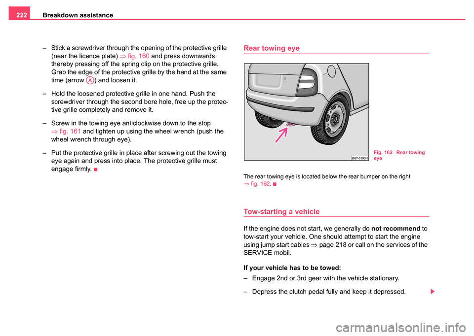
Rear towing eye
The rear towing eye is located below the rear bumper on the right
⇒fig. 162 .
Tow-starting a vehicle
If the engine does not start, we generally do not recommend to
tow-start your vehicle. One should attempt to start the engine
using jump start cables ⇒page 218 or call on the services of the
SERVICE mobil.
If your vehicle has to be towed:
– Engage 2nd or 3rd gear with the vehicle stationary.
– Depress the clutch pedal fully and keep it depressed.
AA
Fig. 162 Rear towing
eye
Page 225 of 247
Fuses and light bulbs
224
Fuses and light bulbs
Electric fuses
Replacing fuses
Defect fuses must be replaced.
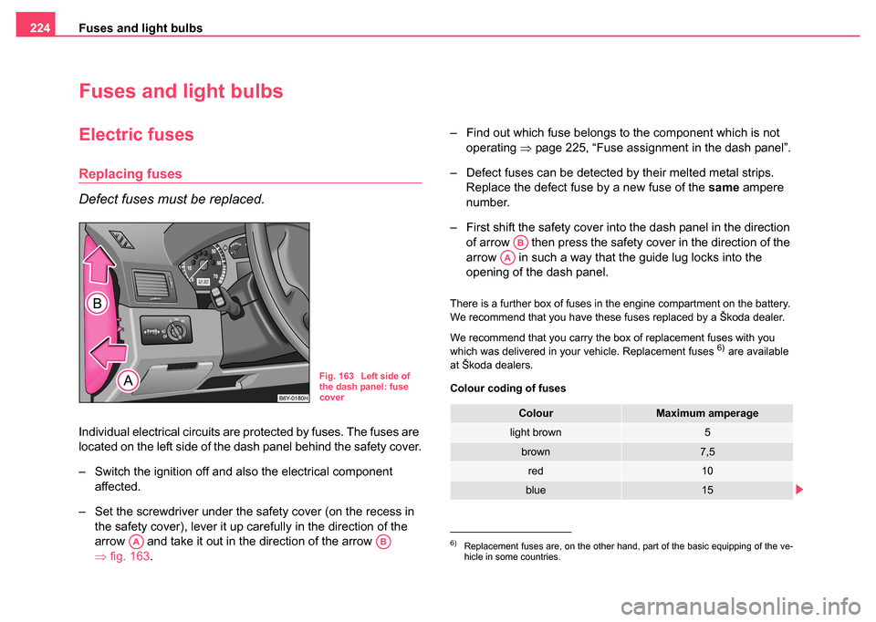
Individual electrical circuits are protected by fuses. The fuses are
located on the left side of the dash panel behind the safety cover.
– Switch the ignition off and also the electrical component
affected.
– Set the screwdriver under the safety cover (on the recess in the safety cover), lever it up carefully in the direction of the
arrow and take it out in the direction of the arrow
⇒fig. 163 . – Find out which fuse belongs to the component which is not
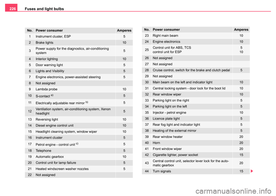
operating ⇒page 225, “Fuse assignment in the dash panel”.
– Defect fuses can be detected by their melted metal strips. Replace the defect fuse by a new fuse of the same ampere
number.
– First shift the safety cover into the dash panel in the direction of arrow then press the safety cover in the direction of the
arrow in such a way that the guide lug locks into the
opening of the dash panel.
There is a further box of fuses in the engine compartment on the battery.
We recommend that you have these fuses replaced by a Škoda dealer.
We recommend that you carry the box of replacement fuses with you
which was delivered in your vehicle. Replacement fuses
6) are available
at Škoda dealers.
Colour coding of fuses
Fig. 163 Left side of
the dash panel: fuse
cover
AAAB6)Replacement fuses are, on the other hand, part of the basic equipping of the ve-
hicle in some countries.
ColourMaximum amperage
light brown5
brown7,5
red10
blue15
AB
AA
Page 227 of 247
Fuses and light bulbs
226
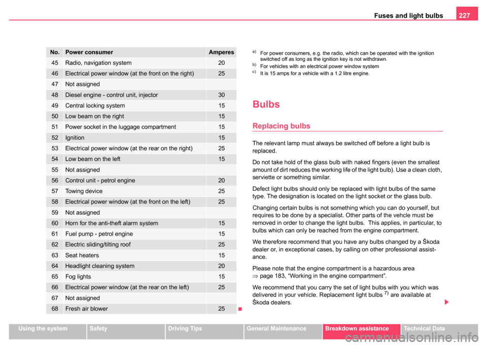
No.Power consumerAmperes
1Instrument cluster, ESP5
2Brake lights10
3Power supply for the diagnostics, air-conditioning
system5
4Interior lighting10
5Door warning light 5
6Lights and Visibility5
7Engine electronics, power-assisted steering5
8Not assigned
9Lambda probe10
10S-contact a)5
11Electrically adjustable rear mirror b)5
12Ventilation system, air-conditioning system, Xenon
headlight5
13Reversing light10
14Diesel engine control unit10
15Headlight cleaning system, window wiper10
16Instrument cluster5
17Petrol engine - control unit c)5
18Telephone5
19Automatic gearbox10
20Control unit for lamp failure5
21Heated windscreen washer nozzles5
22Not assigned
23Right main beam10
24Engine electronics10
25Control unit for ABS, TCS
control unit for ESP5
10
26Not assigned
27Not assigned
28Cruise control, switch for the brake and clutch pedal5
29Not assigned
30Main beam on the left and indicator light10
31Central locking system - door lock for the boot lid10
32Rear window wiper10
33Parking light on the right5
34Parking light on the left5
35Injector - petrol engine10
36Licence plate light5
37Rear fog light and indicator light5
38Heating of the external mirror5
39Rear window heater20
40Horn20
41Front window wiper20
42Cigarette lighter, power socket15
43Central control unit, selector lever lock for the auto-
matic gearbox20
44Turn signals15
No.Power consumerAmperes
Page 228 of 247
Fuses and light bulbs227
Using the systemSafetyDriving TipsGeneral MaintenanceBreakdown assistanceTechnical Data
Bulbs
Replacing bulbs
The relevant lamp must always be switched off before a light bulb is
replaced.
Do not take hold of the glass bulb with naked fingers (even the smallest
amount of dirt reduces the working life of the light bulb). Use a clean cloth,
serviette or something similar.
Defect light bulbs should only be replaced with light bulbs of the same
type. The designation is located on the light socket or the glass bulb.
Changing certain bulbs is not something which you can do yourself, but
requires to be done by a specialist. Other parts of the vehcle must be
removed in order to change the light bulbs. This applies, in particular, to
bulbs which can only be reached from the engine compartment.
We therefore recommend that you have any bulbs changed by a Škoda
dealer or, in exceptional cases, by calling on other professional assist-
ance.
Please note that the engine compartment is a hazardous area
⇒page 183, “Working in the engine compartment”.
We recommend that you carry the set of light bulbs with you which was
delivered in your vehicle. Replacement light bulbs
7) are available at
Škoda dealers.
45Radio, navigation system20
46Electrical power window (at the front on the right)25
47Not assigned
48Diesel engine - control unit, injector30
49Central locking system15
50Low beam on the right15
51Power socket in the luggage compartment15
52Ignition15
53Electrical power window (at the rear on the right)25
54Low beam on the left15
55Not assigned
56Control unit - petrol engine20
57Towing device25
58Electrical power window (at the front on the left)25
59Not assigned
60Horn for the anti-theft alarm system15
61Fuel pump - petrol engine15
62Electric sliding/tilting roof25
63Seat heaters15
64Headlight cleaning system20
65Fog lights15
66Electrical power window (at the rear on the left)25
67Not assigned
68Fresh air blower25
No.Power consumerAmperesa)For power consumers, e.g. the radio, which can be operated with the ignition
switched off as long as the ignition key is not withdrawn.
b)For vehicles with an electrical power window systemc)It is 15 amps for a vehicle with a 1.2 litre engine.
Page 231 of 247
Fuses and light bulbs
230
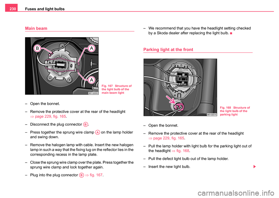
Main beam
– Open the bonnet.
– Remove the protective cover at the rear of the headlight
⇒page 229, fig. 165.
– Disconnect the plug connector .
– Press together the sprung wire clamp on the lamp holder and swing down.
– Remove the halogen lamp with cable. Insert the new halogen lamp in such a way that the fixing lug on the reflector lies in the
corresponding recess in the lamp plate.
– Close the sprung wire clamp over the plate. Press together the sprung wire clamp and lock together again.
– Plug into the plug connector ⇒fig. 167. – We recommend that you have the headlight setting checked
by a Skoda dealer after replacing the light bulb.
Parking light at the front
– Open the bonnet.
– Remove the protective cover at the rear of the headlight ⇒page 229, fig. 165 .
– Pull the lamp holder with light bulb for the parking light out of the headlight ⇒fig. 168.
– Pull the defect light bulb out of the lamp holder.
– Insert the new light bulb.
Fig. 167 Structure of
the light bulb of the
main beam light
AB
AA
AB
Fig. 168 Structure of
the light bulb of the
parking light
Page 232 of 247
Fuses and light bulbs231
Using the systemSafetyDriving TipsGeneral MaintenanceBreakdown assistanceTechnical Data
– Insert the lamp holder with new light bulb into of the
headlight.
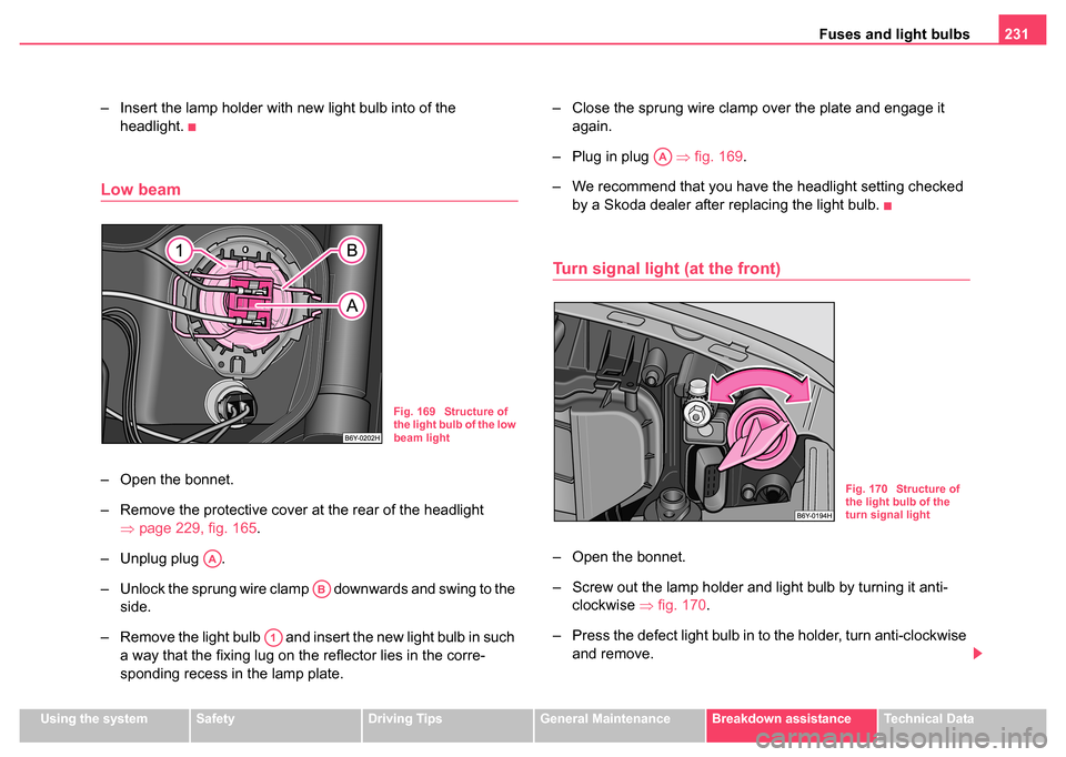
Low beam
– Open the bonnet.
– Remove the protective cover at the rear of the headlight ⇒page 229, fig. 165.
– Unplug plug .
– Unlock the sprung wire clamp downwards and swing to the side.
– Remove the light bulb and insert the new light bulb in such a way that the fixing lug on the reflector lies in the corre-
sponding recess in the lamp plate. – Close the sprung wire clamp over the plate and engage it
again.
– Plug in plug ⇒fig. 169 .
– We recommend that you have the headlight setting checked by a Skoda dealer after replacing the light bulb.
Turn signal light (at the front)
– Open the bonnet.
– Screw out the lamp holder and light bulb by turning it anti-clockwise ⇒fig. 170 .
– Press the defect light bulb in to the holder, turn anti-clockwise and remove.
Fig. 169 Structure of
the light bulb of the low
beam light
AA
AB
A1
AA
Fig. 170 Structure of
the light bulb of the
turn signal light
Page 235 of 247
Fuses and light bulbs
234
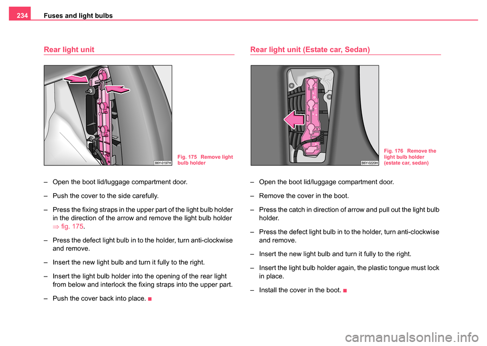
Rear light unit
– Open the boot lid/luggage compartment door.
– Push the cover to the side carefully.
– Press the fixing straps in the upper part of the light bulb holder
in the direction of the arrow and remove the light bulb holder
⇒fig. 175 .
– Press the defect light bulb in to the holder, turn anti-clockwise and remove.
– Insert the new light bulb and turn it fully to the right.
– Insert the light bulb holder into the opening of the rear light from below and interlock the fixing straps into the upper part.
– Push the cover back into place.
Rear light unit (Estate car, Sedan)
– Open the boot lid/luggage compartment door.
– Remove the cover in the boot.
– Press the catch in direction of arrow and pull out the light bulb holder.
– Press the defect light bulb in to the holder, turn anti-clockwise and remove.
– Insert the new light bulb and turn it fully to the right.
– Insert the light bulb holder again, the plastic tongue must lock in place.
– Install the cover in the boot.
Fig. 175 Remove light
bulb holderFig. 176 Remove the
light bulb holder
(estate car, sedan)
Page 236 of 247
Fuses and light bulbs235
Using the systemSafetyDriving TipsGeneral MaintenanceBreakdown assistanceTechnical Data
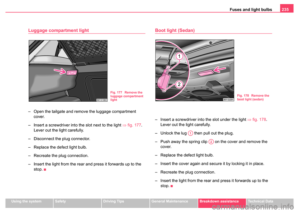
Luggage compartment light
– Open the tailgate and remove the luggage compartment
cover.
– Insert a screwdriver into the slot next to the light ⇒fig. 177 .
Lever out the light carefully.
– Disconnect the plug connector.
– Replace the defect light bulb.
– Recreate the plug connection.
– Insert the light from the rear and press it forwards up to the stop.
Boot light (Sedan)
– Insert a screwdriver into the slot under the light ⇒fig. 178.
Lever out the light carefully.
– Unlock the lug then pull out the plug.
– Push away the spring clip on the cover and remove the cover.
– Replace the defect light bulb.
– Insert the cover again and secure it by locking it in place.
– Recreate the plug connection.
– Insert the light from the rear and press it forwards up to the stop.
Fig. 177 Remove the
luggage compartment
lightFig. 178 Remove the
boot light (sedan)
A1
A2
Page 238 of 247

General237
Using the systemSafetyDriving TipsGeneral MaintenanceBreakdown assistanceTechnical Data
Technical Data
General
Identification data
Vehicle data sticker
The vehicle data sticker ⇒fig. 179 is located on the floor of the luggage
compartment and is also stated in the Service Schedule.
The vehicle data sticker contains the following data:
Vehicle identification number (VIN)
Vehicle type
Gearbox code, paint number, interior equipment number, engine
output, engine code
Partial description of the vehicle Vehicle identification number (VIN)
The vehicle identification number - VIN (vehicle body number) is stamped
into the engine compartment on the right hand shock absorber dome. This
number is also located on a sign on the lower left hand edge below the
windscreen.
Engine number
The engine number is stamped into the engine block.
Type plate (production plate)
The type plate is located in the engine compartment at the front on the left
hand shock absorber dome.
Homologation sign
The homologation sign is located on the lock carrier. Vehicles for certain
countries do not have an homologation sign.
Stickers on inside of fuel filler flap
The stickers are affixed to the inside of the fuel filler flap. The sticker
contains the following data:
•The prescribed types of fuel
•Tyre size
•Tyre pressure
Note
•You will find the technical data of your vehicle in the separate brochure
"Technical Data".
Fig. 179 Vehicle data
sticker
A1
A2
A3
A4