ESP SKODA FABIA 2012 2.G / 5J User Guide
[x] Cancel search | Manufacturer: SKODA, Model Year: 2012, Model line: FABIA, Model: SKODA FABIA 2012 2.G / 5JPages: 196, PDF Size: 4.83 MB
Page 43 of 196
The fog lights with the function CORNER are adjusted according to the steering
angle or after switching on the turn signal light
1)
in the following circumstances:
› the vehicle is stationary and the engine is running or it moves with a speed of
maximum 40 km/h;
› the daytime running lights are not switched on;
› the low beam is switched on;
› the fog lights are not switched on;
› no reverse gear is engaged. ÐRear fog light
First read and observe the introductory information and safety warn-
ings on page 38.
Switching on
› First of all, turn the light switch
» Fig. 23 on page 40 to position or .
› Pull the light switch to position 2
.
If the vehicle is not fitted with fog lights » page 40, the rear fog light is switched
on by turning the light switch to the position or and is pulled out directly to
the position 2
. This switch does not have two positions, but only one position.
The warning light
lights up in the instrument cluster when the rear fog light is
switched on » page 17.
Only the rear fog light on the trailer lights up if the vehicle has a factory-fitted
towing device or a towing device from ŠKODA original accessories and it is driven
with a trailer and the rear fog light switched on. Ð
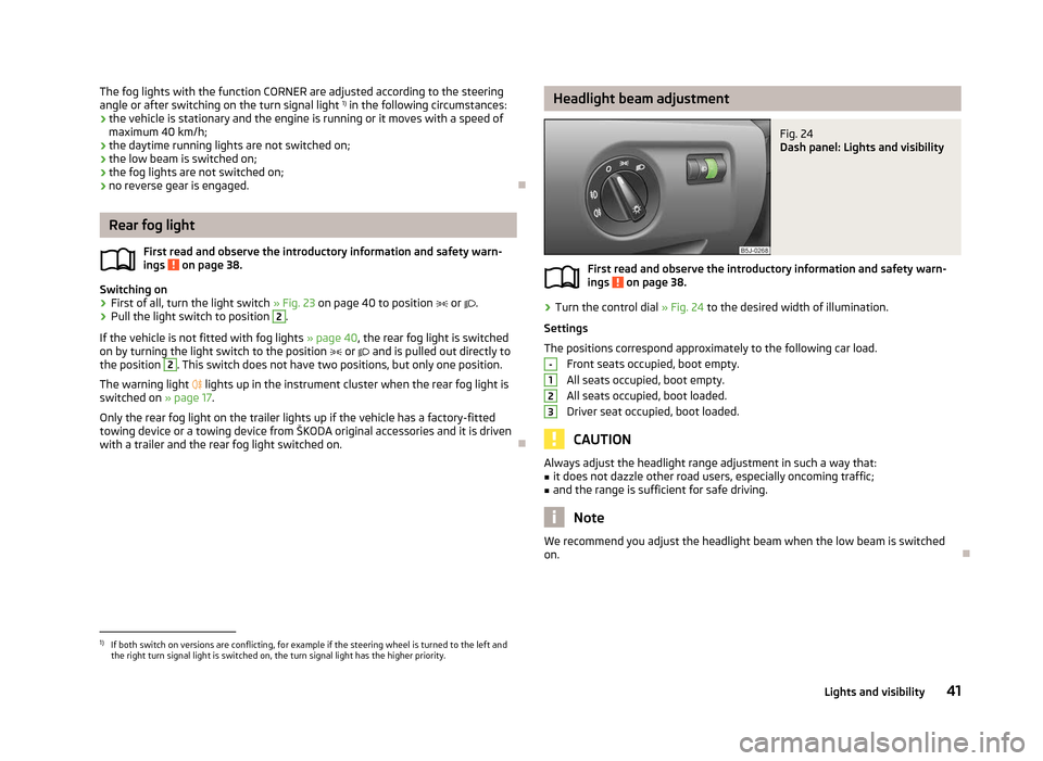
ä Headlight beam adjustment
Fig. 24
Dash panel: Lights and visibility
First read and observe the introductory information and safety warn-
ings on page 38.
›
Turn the control dial
» Fig. 24 to the desired width of illumination.
Settings
The positions correspond approximately to the following car load. Front seats occupied, boot empty.
All seats occupied, boot empty.
All seats occupied, boot loaded.
Driver seat occupied, boot loaded. CAUTION
Always adjust the headlight range adjustment in such a way that:
■ it does not dazzle other road users, especially oncoming traffic;
■ and the range is sufficient for safe driving. Note
We recommend you adjust the headlight beam when the low beam is switched
on. Ð
ä -
1
2
3
1)
If both switch on versions are conflicting, for example if the steering wheel is turned to the left and
the right turn signal light is switched on, the turn signal light has the higher priority.
41
Lights and visibility
Page 45 of 196
Note
■ The turn signal system only operates when the ignition is switched on. The cor-
responding warning light or in the instrument cluster also flashes.
■ The turn signal is automatically cancelled after negotiating a curve.
■ The warning light flashes at twice its normal rate if a bulb for the turn signal
light fails. ÐInterior light
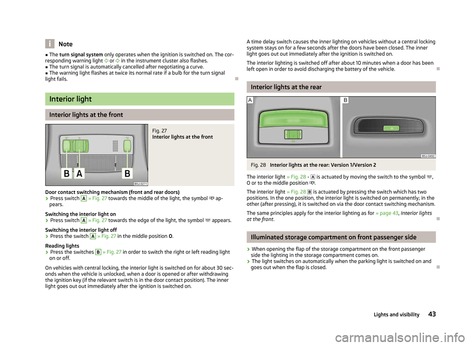
Interior lights at the front
Fig. 27
Interior lights at the front
Door contact switching mechanism (front and rear doors) › Press switch A
» Fig. 27 towards the middle of the light, the symbol
ap-
pears.
Switching the interior light on
› Press switch A
» Fig. 27 towards the edge of the light, the symbol
appears.
Switching the interior light off
› Press the switch A
» Fig. 27 in the middle position
O.
Reading lights
› Press the switches B
» Fig. 27 in order to switch the right or left reading light
on or off.
On vehicles with central locking, the interior light is switched on for about 30 sec-
onds when the vehicle is unlocked, when a door is opened or after withdrawing
the ignition key (if the relevant switch is in the door contact position). The inner
light goes out out immediately after the ignition is switched on. A time delay switch causes the inner lighting on vehicles without a central locking
system stays on for a few seconds after the doors have been closed. The inner
light goes out out immediately after the ignition is switched on.
The interior lighting is switched off after about 10 minutes when a door has been
left open in order to avoid discharging the battery of the vehicle. Ð Interior lights at the rear
Fig. 28
Interior lights at the rear: Version 1/Version 2
The interior light » Fig. 28 -
is actuated by moving the switch to the symbol ,
O or to the middle position .
The interior light » Fig. 28 is actuated by pressing the switch which has two
positions. In the one position, the interior light is switched on permanently; in the
other (after pressing), it is switched on via the door contact switching mechanism.
The same principles apply for the interior lighting as for » page 43, Interior lights
at the front . Ð Illuminated storage compartment on front passenger side
› When opening the flap of the storage compartment on the front passenger
side the lighting in the storage compartment comes on.
› The light switches on automatically when the parking light is switched on and
goes out when the flap is closed. Ð
43
Lights and visibility
Page 55 of 196
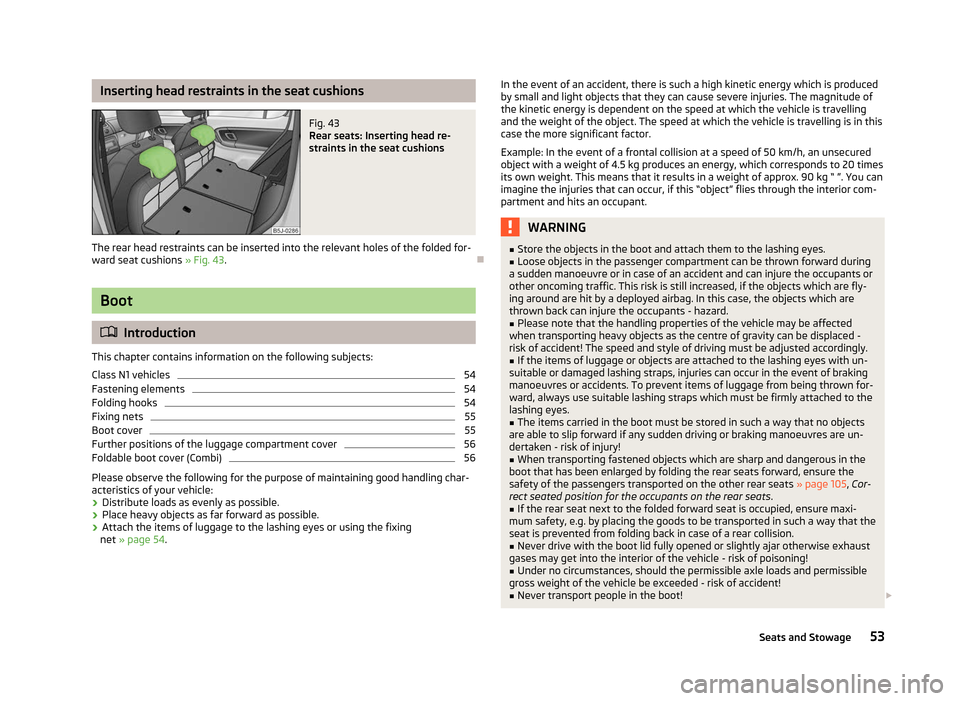
Inserting head restraints in the seat cushions
Fig. 43
Rear seats: Inserting head re-
straints in the seat cushions
The rear head restraints can be inserted into the relevant holes of the folded for-
ward seat cushions » Fig. 43. ÐBoot
ä
Introduction
This chapter contains information on the following subjects:
Class
N1 vehicles 54
Fastening elements 54
Folding hooks 54
Fixing nets 55
Boot cover 55
Further positions of the luggage compartment cover 56
Foldable boot cover (Combi) 56
Please observe the following for the purpose of maintaining good handling char-
acteristics of your vehicle:
› Distribute loads as evenly as possible.
› Place heavy objects as far forward as possible.
› Attach the items of luggage to the lashing eyes or using the fixing
net »
page 54 . In the event of an accident, there is such a high kinetic energy which is produced
by small and light objects that they can cause severe injuries. The magnitude of
the kinetic energy is dependent on the speed at which the vehicle is travelling
and the weight of the object. The speed at which the vehicle is travelling is in this
case the more significant factor.
Example: In the event of a frontal collision at a speed of 50
km/h, an unsecured
object with a weight of 4.5 kg produces an energy, which corresponds to 20 times
its own weight. This means that it results in a weight of approx. 90 kg “ ”. You can
imagine the injuries that can occur, if this “object” flies through the interior com-
partment and hits an occupant. WARNING
■ Store the objects in the boot and attach them to the lashing eyes.
■ Loose objects in the passenger compartment can be thrown forward during
a sudden manoeuvre or in case of an accident and can injure the occupants or
other oncoming traffic. This risk is still increased, if the objects which are fly-
ing around are hit by a deployed airbag. In this case, the objects which are
thrown back can injure the occupants - hazard. ■ Please note that the handling properties of the vehicle may be affected
when transporting heavy objects as the centre of gravity can be displaced -
risk of accident! The speed and style of driving must be adjusted accordingly. ■ If the items of luggage or objects are attached to the lashing eyes with un-
suitable or damaged lashing straps, injuries can occur in the event of braking
manoeuvres or accidents. To prevent items of luggage from being thrown for-
ward, always use suitable lashing straps which must be firmly attached to the
lashing eyes. ■ The items carried in the boot must be stored in such a way that no objects
are able to slip forward if any sudden driving or braking manoeuvres are un-
dertaken - risk of injury!
■ When transporting fastened objects which are sharp and dangerous in the
boot that has been enlarged by folding the rear seats forward, ensure the
safety of the passengers transported on the other rear seats »
page 105, Cor-
rect seated position for the occupants on the rear seats .
■ If the rear seat next to the folded forward seat is occupied, ensure maxi-
mum safety, e.g. by placing the goods to be transported in such a way that the
seat is prevented from folding back in case of a rear collision.
■ Never drive with the boot lid fully opened or slightly ajar otherwise exhaust
gases may get into the interior of the vehicle - risk of poisoning!
■ Under no circumstances, should the permissible axle loads and permissible
gross weight of the vehicle be exceeded - risk of accident!
■ Never transport people in the boot! £
53
Seats and Stowage
Page 74 of 196
Note
If the air distribution is positioned towards the windows, the total amount of air is
used to defrost the windows and thus no air will be fed to the footwell. This can
lead to restriction of the heating comfort. ÐSet heating
Recommended basic settings of the heating controls for the respective operating
modes:
Set-up Setting of the control dial
Button 1
Air outlet vents 4
A B C
Defrosting the windshield and side
windows
To the right up to the
stop 3
Do not switch on Open and align with the side win-
dow
Free windshield and side windows
from mist Desired temperature 2 or 3
Do not switch on Open and align with the side win-
dow
The fastest heating To the right up to the
stop 3
Briefly switch on
Opening
Comfortable heating Desired temperature 2 or 3
Do not switch on
Opening
Fresh air mode - ventilation To the left up to the
stop Desired position
Do not switch on
OpeningNote
■ Controls A
» Fig. 78 on page 71, B
, C
and the button 1
.
■ Air outlet vents 4 » Fig. 77 on page 71 .
■ We recommend that you leave the air outlet vents 3 » Fig. 77 on page 71 in the
opened position. ÐRecirculated air mode
Recirculated air mode prevents polluted air outside the vehicle from getting into
the vehicle, for example when driving through a tunnel or when standing in a
traffic jam. Switching on
› Press the button
1
» Fig. 78 on page 71
and the warning light in the button
illuminates.
Switching off
› Press the button
1
» Fig. 78 on page 71again - the warning light in the but-
ton goes out.
Recirculated air mode is switched off automatically if the air distribution control C
» Fig. 78 on page 71
is turned to position . Recirculated air mode can be
switched on again from this setting by repeatedly pressing the button .
£
72 Using the system
Page 77 of 196
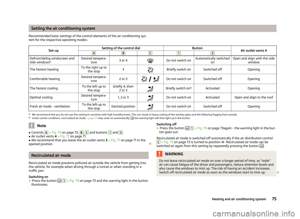
Setting the air conditioning system
Recommended basic settings of the control elements of the air conditioning sys-
tem for the respective operating modes:
Set-up Setting of the control dial
Button
Air outlet vents 4 A B C 1 2
Defrost/defog windscreen and
side windows
a) Desired tempera-
ture 3 or 4
Do not switch on Automatically switched
on Open and align with the side
window
The fastest heating To the right up to
the stop 3
Briefly switch on Switched off
Opening
Comfortable heating Desired tempera-
ture 2 or 3
Do not switch on Switched off
Opening
The fastest cooling To the left up to
the stop briefly 4, then
2 or 3 Briefly switch on
b)
Activated Opening
Optimal cooling Desired tempera-
ture 1, 2 or 3
Do not switch on Activated Open and align to the roof
Fresh air mode - ventilation To the left up to
the stop Desired position
Do not switch on Switched off
Openinga)
We recommend that you do not use this setting in countries with high humidity levels. This can result in heavy cooling of the window glass and the following fogging from outside.
b) Under certain conditions, recirculated air mode » page 75 may come on automatically; the warning light will then light up in the button.
Note
■ Controls A
» Fig. 79 on page 73
, B
, C
and buttons 1
and 2
.
■ Air outlet vents 4 » Fig. 77 on page 71 .
■ We recommend that you leave the air outlet vents 3 » Fig. 77 on page 71 in the
opened position. ÐRecirculated air mode
Recirculated air mode prevents polluted air outside the vehicle from getting into
the vehicle, for example when driving through a tunnel or when standing in a
traffic jam.
Switching on
› Press the button
1
» Fig. 79 on page 73
and the warning light in the button
illuminates. Switching off
› Press the button
1
» Fig. 79 on page 73
again - the warning light in the but-
ton goes out.
Recirculated air mode is switched off automatically if the air distribution control C
» Fig. 79 on page 73
is turned to position . Recirculated air mode can be
switched on again from this setting by repeatedly pressing the button .
WARNING
Do not leave recirculated air mode on over a longer period of time, as “stale”
air can cause fatigue of the driver and passengers, reduce attention levels and
also cause the windows to mist up. The risk of having an accident increases.
Switch off recirculated air mode as soon as the windows start to mist up. Ð
75
Heating and air conditioning system
Page 79 of 196
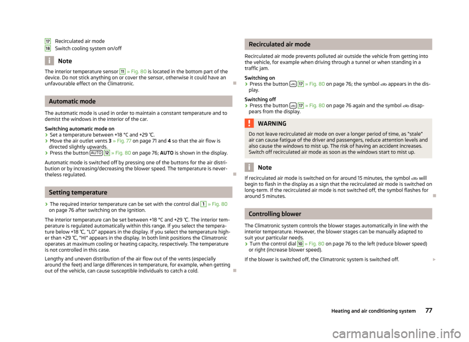
Recirculated air mode
Switch cooling system on/off
Note
The interior temperature sensor 11
» Fig. 80
is located in the bottom part of the
device. Do not stick anything on or cover the sensor, otherwise it could have an
unfavourable effect on the Climatronic. ÐAutomatic mode
The automatic mode is used in order to maintain a constant temperature and to
demist the windows in the interior of the car.
Switching automatic mode on
› Set a temperature between +18 °C and +29
℃.
› Move the air outlet vents
3 » Fig. 77 on page 71 and 4 so that the air flow is
directed slightly upwards.
› Press the button
AUTO 12
» Fig. 80
on page
76; AUTO is shown in the display.
Automatic mode is switched off by pressing one of the buttons for the air distri-
bution or by increasing/decreasing the blower speed. The temperature is never-
theless regulated. ÐSetting temperature
› The required interior temperature can be set with the control dial 1
» Fig. 80
on page 76 after switching on the ignition.
The interior temperature can be set between +18 °C and +29 ℃. The interior tem-
perature is regulated automatically within this range. If you select the tempera-
ture below +18 ℃, “LO
” appears in the display. If you select the temperature high-
er than +29 ℃, “HI” appears in the display. In both limit positions the Climatronic
operates at maximum cooling or heating capacity, respectively. The temperature
is not controlled in this case.
Lengthy and uneven distribution of the air flow out of the vents (especially
around the feet) and large differences in temperature, for example, when getting
out of the vehicle, can cause susceptible individuals to catch a cold. Ð17
18 Recirculated air mode
Recirculated air mode prevents polluted air outside the vehicle from getting into
the vehicle, for example when driving through a tunnel or when standing in a
traffic jam.
Switching on
› Press the button
17
» Fig. 80
on page
76; the symbol appears in the dis-
play.
Switching off
› Press the button
17
» Fig. 80
on page
76 again and the symbol disap-
pears from the display. WARNING
Do not leave recirculated air mode on over a longer period of time, as “stale”
air can cause fatigue of the driver and passengers, reduce attention levels and
also cause the windows to mist up. The risk of having an accident increases.
Switch off recirculated air mode as soon as the windows start to mist up. Note
If recirculated air mode is switched on for around 15 minutes, the symbol will
begin to flash in the display as a sign that the recirculated air mode is switched on
long-term. If the recirculated air mode is not switched off, the symbol flashes for
around 5 minutes. Ð Controlling blower
The Climatronic system controls the blower stages automatically in line with the
interior temperature. However, the blower stages can be manually adapted to
suit your particular needs.
› Turn the control dial 10
» Fig. 80 on page 76 to the left (reduce blower speed)
or right (increase blower speed).
If the blower is switched off, the Climatronic system is switched off. £
77
Heating and air conditioning system
Page 87 of 196
XDL function (Fabia RS and Fabia Estate RS only)
XDL is an extension to the electronic differential lock. XDL does not respond to
traction, but to the relief of the inner front wheel during fast cornering. The active
brake intervention on the brake of the inner wheel prevents it from spinning.
Thus, the traction is improved and the vehicle continues to follow the desired
track.
ÐShifting (manual gearbox)
Fig. 85
Shift pattern of the 5-speed
manual gearbox
Always depress the clutch pedal fully when changing gear, to prevent excessive
wear of the clutch.
The gearshift indicator must be observed when changing gear » page 11, Recom-
mended gear .
Only engage reverse gear when the vehicle is stationary. Depress the clutch pedal
and hold it fully depressed. Wait a moment before reverse gear is engaged to
avoid any shift noises.
The reversing light will come on once reverse gear is engaged, provided the igni-
tion is on. WARNING
Never engage reverse gear when driving - risk of accident! Note
If not in the process of changing gear, do not leave your hand on the gearshift
lever while driving. The pressure from the hand can cause the gearshift mecha-
nism to wear excessively. Ð pedals
The operation of the pedals must not be hindered under any circumstances!
In the driver's footwell, only a footmat, which is attached to the two correspond-
ing attachment points, may be used.
Only use footmats from the range of
ŠKODA Original Accessories, which are fitted
to two attachment points. WARNING
No objects are allowed in the driver's footwell – risk of obstruction or limita-
tion in operating the pedal! Ð Parking aid
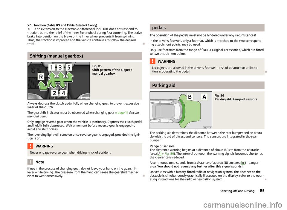
Fig. 86
Parking aid: Range of sensors
The parking aid determines the distance between the rear bumper and an obsta-
cle with the aid of ultrasound sensors. The sensors are integrated in the rear
bumper.
Range of sensors
The clearance warning begins at a distance of about 160 cm from the obstacle
(area A
» Fig. 86
). The interval between the warning signals becomes shorter as
the clearance is reduced.
A continuous tone sounds from a distance of approx. 30 cm (area B
) - danger
area. You should not reverse any further after this signal sounds!
On vehicles with a factory-fitted radio or navigation system, the distance to the
obstacle is simultaneously graphically illustrated on the display, refer to the oper-
ating instructions for the radio or navigation system. £
85
Starting-off and Driving
Page 88 of 196
On vehicles with a factory-fitted towing device, the border of the danger area
starts (continuous tone) 5
cm further away from the vehicle. The length of the ve-
hicle can be increased with an installed detachable towing device.
On vehicles with a factory-fitted towing device, the rear sensors are deactivated
when towing a trailer.
Activating/deactivating the parking aid
The parking aid is activated automatically when reverse gear is engaged and the
ignition is turned on. This is confirmed by a brief audible signal.
The parking aid is deactivated by removing the reverse gear. WARNING
■ The parking aid is not a substitute for the driver paying proper attention and
it is always the driver's responsibility to take care when reversing the vehicle
or carrying out similar manoeuvres. Pay particular attention to small children
and animals as they are not recognised by the parking aid sensors.
■ Before reversing or parking, check that there is no small obstacle, such as a
rock, thin post, trailer drawbar etc., in front of or behind the vehicle. Such ob-
stacles may not be recognised by the parking aid sensors.
■ Under certain circumstances, surfaces of certain objects and types of cloth-
ing cannot reflect the signals from the parking aid. Thus, these objects or peo-
ple who wear such clothing are not recognised by the parking aid sensors.
■ External sound sources can have a detrimental effect on the parking aid.
Under unfavourable conditions, objects or people may not be recognised. Note
■ If a warning signal sounds for about 3
seconds after activating the system and
there is no obstacle close to your car, this indicates a system fault. Have the fault
rectified by a ŠKODA specialist garage. ■ The sensors must be kept clean (free of ice, etc.) to enable the parking aid to
operate properly.
■ If the parking aid is activated and the selector lever of the automatic gearbox is
in the position P, the warning signal is interrupted (the vehicle cannot move). Ð Cruise control system (CCS)
ä
Introduction
This chapter contains information on the following subjects:
Storing a speed 87
Changing a stored speed 87
Switching off the cruise control system temporarily 87
Switching off the cruise control system completely 87
The cruise control system (CCS) maintains a constant speed, more than 30 km/h,
once it has been set, without you having to depress the accelerator pedal. This is
only possible within the range which is permitted by the power output and brak-
ing power of the engine.
The warning light illuminates in the instrument cluster when the cruise control
system is activated. WARNING
■ For safety reasons, the cruise control system must not be used in dense
traffic or on unfavourable road surfaces (such as icy roads, slippery roads,
loose gravel) - risk of accident!
■ The saved speed may only be resumed if it is not too high for the current
traffic conditions.
■ Always switch off the cruise control system after use to prevent uninten-
tional use of the system. CAUTION
■ Always depress the clutch pedal if switching to the neutral position (vehicle
with a manual gearbox) when the cruise control system is switched on! Otherwise
the engine can rev up unintentionally.
■ The cruise control system is not able to maintain a constant speed when driving
in areas with steeper gradients. The weight of the vehicle increases the speed at
which it travels. Therefore, shift to a lower gear in good time or slow the vehicle
down by applying the foot brake. £
86 Using the system
Page 95 of 196
Selector lever lock
First read and observe the introductory information and safety warn-
ings on page 90.
Automatic selector lever lock
With the ignition on, the selector lever is locked when it is in the positions P and
N. The brake pedal must be depressed to move the selector lever out of this posi-
tion. The warning light » page 24, Selector lever lock illuminates in the in-
strument cluster as a reminder for the driver when the selector lever is in the po-
sitions P and N.
The selector lever is not locked when quickly moving across the position
N (e.g.
from R to D). This, for example, helps to rock out a vehicle that is stuck. The selec-
tor lever lock will click into place if the lever is in the N position for more than 2
seconds without the brake pedal being pressed.
The selector lever lock is only active if the vehicle is stationary or moving at speed
of less than 5 km/hour. The lock is switched off automatically into position N
when the car is travelling at a higher speed.
Shiftlock button
The Shiftlock button in the handle of selector lever prevents certain selector lever
positions being engaged inadvertently. The selector lever lock is cancelled when
the Shiftlock button is pressed.
Ignition key withdrawal lock 1)
After the ignition is switched off, the ignition key can only be withdrawn if the se-
lector lever is in the position P. If the ignition key is withdrawn, the selector lever
is blocked in position P. ÐKickdown function
First read and observe the introductory information and safety warn-
ings on page 90.
The kickdown function provides you with maximum acceleration power.
When the accelerator pedal is fully depressed, the kickdown function is activated
in the desired driving program. This function has precedence over the driving pro-
gramme and serves for maximum acceleration of the vehicle when exploiting the
ä
ä
maximum power potential of the engine without taking into account the current
selector lever position (
D, S or Tiptronic ). The gearbox shifts down to one or sev-
eral gears in line with the driving state and the vehicle accelerates. The gearbox
does not shift up into the highest gear until the engine has reached its maximum
revolutions for this gear range. Ð Dynamic shift programme
First read and observe the introductory information and safety warn-
ings on page 90.
The automatic gearbox of your vehicle is controlled electronically. Shifting up and
down through the gears is performed automatically on the basis of pre-defined
driving programmes.
Adopting a moderate style of driving
will cause the gearbox to select the most
economical driving programme. Shifting up into a higher gear as soon as possible
and shifting down as late as possible will have a favourable effect on your fuel
consumption.
When adopting a sporty style of driving with rapid movements of the accelerator
pedal combined with sharp acceleration, frequent changes in speed and exploit-
ing the top speed of the car, the gearbox will adjust to this style of driving once
the accelerator pedal (kickdown function) is depressed and will shift down earlier,
frequently by several gears in comparison to a moderate style of driving.
Selecting the most appropriate driving programme for the particular style of driv-
ing is a continuous process. Irrespective of this it is, however, possible to switch
or shift down into a dynamic shift programme by depressing the accelerator rap-
idly. The gearbox shifts down into a lower gear in accordance with the speed,
therefore enabling rapid acceleration (e.g. when overtaking) without the accelera-
tor pedal having to be depressed into the kickdown range. The original pro-
gramme will be reactivated to match your particular style of driving once the
gearbox has shifted up again.
When driving in hilly regions, the gears are selected to match uphill and downhill
sections. This avoids the gearbox frequently shifting up and down when negoti-
ating an uphill stretch. When driving downhill, it is possible to shift down into the
Tiptronic position, in order to exploit the engine brake torque. Ð
ä
1)
Only valid for some countries.
93
Automatic gearbox
Page 96 of 196
Emergency programme
First read and observe the introductory information and safety warn-
ings on page 90.
An emergency programme exists in the event of a fault in the system.
The gearbox operates in a corresponding emergency programme if there are
functional faults in the gearbox electronics. All of the display elements illuminate
or go out.
A functional fault can have the following effect:
› The gearbox only shifts into certain gears;
› The reverse gear
R cannot be used,
› The manual shift programme is switched off in emergency mode. Note
If the gearbox has switched to emergency mode, drive to a ŠKODA specialist ga-
rage to have the fault rectified. ÐSelector lever-emergency unlocking
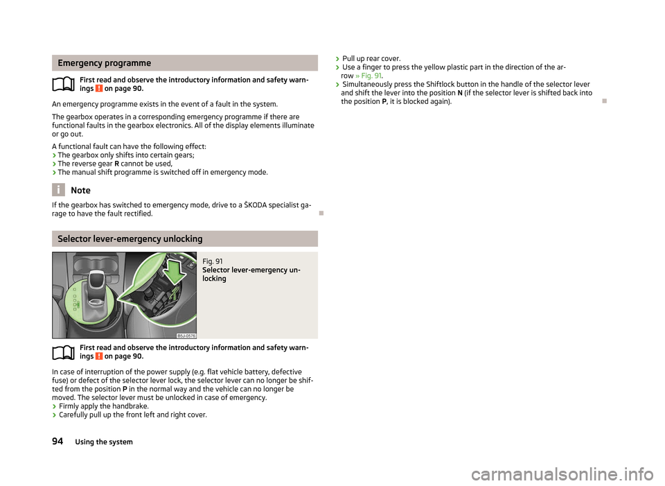
Fig. 91
Selector lever-emergency un-
locking
First read and observe the introductory information and safety warn-
ings on page 90.
In case of interruption of the power supply (e.g. flat vehicle battery, defective
fuse) or defect of the selector lever lock, the selector lever can no longer be shif-
ted from the position
P in the normal way and the vehicle can no longer be
moved. The selector lever must be unlocked in case of emergency.
› Firmly apply the handbrake.
› Carefully pull up the front left and right cover.
ä
ä
›
Pull up rear cover.
› Use a finger to press the yellow plastic part in the direction of the ar-
row » Fig. 91.
› Simultaneously press the Shiftlock button in the handle of the selector lever
and shift the lever into the position N (if the selector lever is shifted back into
the position P , it is blocked again). Ð94
Using the system