ESP SKODA FABIA 2012 2.G / 5J Owner's Guide
[x] Cancel search | Manufacturer: SKODA, Model Year: 2012, Model line: FABIA, Model: SKODA FABIA 2012 2.G / 5JPages: 196, PDF Size: 4.83 MB
Page 169 of 196

■
One should be constantly vigilant not to allow impermissibly high towing forces
or jerky loadings. There is always a risk of excessive stresses and damage result-
ing at the points to which you attach the tow rope or tow bar when you attempt
to tow a vehicle which is not standing on a paved road.
■ Attach the tow rope or the tow bar to the towing eyes or to the detachable ball
head of the towing device » page 167
or » page 167.Note
■ We recommend using a tow rope from
ŠKODA Original Accessories available
from a ŠKODA Service Partner. ■ Towing another vehicle requires a certain amount of practice. Both drivers
should be familiar with the particular points about towing a vehicle. Unskilled
drivers should not attempt to tow in another vehicle or to be towed in. ■ When towing, respect the national legal provisions, especially those which re-
late to the identification of the towing vehicle and the vehicle being towed. ■ The tow rope must not be twisted as it may in certain circumstances result in
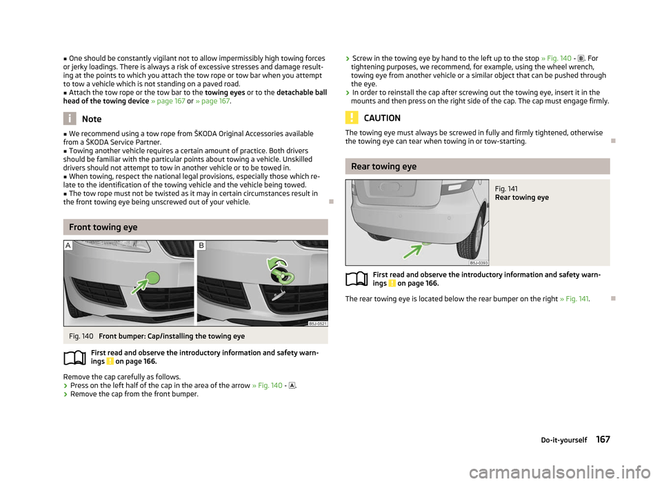
the front towing eye being unscrewed out of your vehicle. ÐFront towing eye
Fig. 140
Front bumper: Cap/installing the towing eye
First read and observe the introductory information and safety warn-
ings on page 166.
Remove the cap carefully as follows.
›
Press on the left half of the cap in the area of the arrow
» Fig. 140 - .
› Remove the cap from the front bumper.
ä ›
Screw in the towing eye by hand to the left up to the stop
» Fig. 140 - . For
tightening purposes, we recommend, for example, using the wheel wrench,
towing eye from another vehicle or a similar object that can be pushed through
the eye.
› In order to reinstall the cap after screwing out the towing eye, insert it in the
mounts and then press on the right side of the cap. The cap must engage firmly. CAUTION
The towing eye must always be screwed in fully and firmly tightened, otherwise
the towing eye can tear when towing in or tow-starting. Ð Rear towing eye
Fig. 141
Rear towing eye
First read and observe the introductory information and safety warn-
ings on page 166.
The rear towing eye is located below the rear bumper on the right
»
Fig. 141. Ð ä
167
Do-it-yourself
Page 172 of 196

No. Power consumer
32 High pressure fuel pump, pressure valve
33 Engine control unit
34 Engine control unit, vacuum pump 35 Power supply of ignition lock
36 Main beam 37 Rear fog light, DC/DC converter START-STOP
38 Fog lights 39 Air blower for heating
40-41 Not assigned 42 Rear window heater
43 Horn
44 Windscreen wipers 45 Central control unit for convenience system
46 Engine control unit, fuel pump 47 Cigarette lighter, power socket in the luggage compartment
48 ABS, START-STOP (DC/DC) converter ESP 49 Turn signal lights, brake lights50 START-STOP (DC/DC) converter infotainment, radio 51 Electrical power window (front and rear) - left side
52 Electrical power window (front and rear) - right side
53 Parking light = left side, electrical sliding/tilting roof
54 START-STOP (instrument cluster), alarm 55 Control unit for automatic gearbox
56 Headlight cleaning system, parking light - right side 57 Left low beam, headlight range adjustment
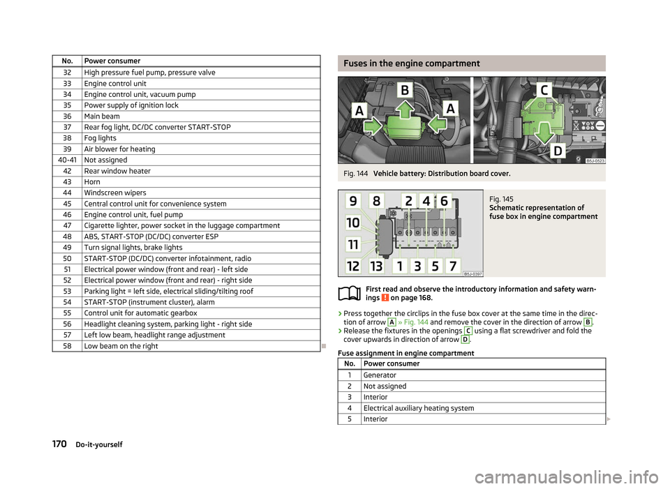
58 Low beam on the right Ð Fuses in the engine compartment
Fig. 144
Vehicle battery: Distribution board cover. Fig. 145
Schematic representation of
fuse box in engine compartment
First read and observe the introductory information and safety warn-
ings on page 168.
›
Press together the circlips in the fuse box cover at the same time in the direc-
tion of arrow A
» Fig. 144
and remove the cover in the direction of arrow B
.
› Release the fixtures in the openings C
using a flat screwdriver and fold the
cover upwards in direction of arrow D
.
Fuse assignment in engine compartment No. Power consumer
1 Generator
2 Not assigned
3 Interior
4 Electrical auxiliary heating system 5 Interior £ ä
170 Do-it-yourself
Page 180 of 196

In the extra-urban driving cycle, the vehicle is accelerated and decelerated in all
gears, corresponding to daily routine driving conditions. The driving speed varies
between 0 and 120 km/h.
The calculation of the combined fuel consumption considers a weighting of about
37
% for the intra-urban cycle and 63 % for the extra-urban cycle. WARNING
Do not exceed the specified maximum permissible weights - risk of accident
and damage. Note
■ If required, you can find out the precise weight of your vehicle by contacting a
ŠKODA
Service Partner.
■ Depending on the range of equipment, style of driving, traffic situation, weather
influences and vehicle condition, consumption values may deviate from the indi-
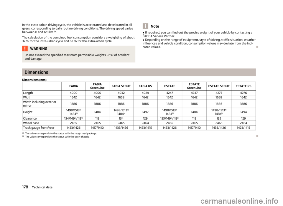
cated values. ÐDimensions
Dimensions (mm) FABIAFABIA
GreenLine FABIA SCOUT FABIA RS ESTATE ESTATE
GreenLine ESTATE SCOUT ESTATE RS
Length 40004000 4032 4029 4247 4247 42754276
Width 164216421658 1642 1642 16421658 1642
Width including exterior
mirror 1886
1886 1886 1886 1886 1886 18861886
Height 1498/1513
a)
1484 b)
1484 1498/1513
a)
1484 b)
1492 1498/1513
a)
1484 b)
1484 1498/1513
a)
1484 b)
1494
Clearance 134/149a)
/119 b)
119 134 129 135/149 a)
/119 b)
119 135 129
Wheel base 24652465 2465 2464 2465 2465 24652464
Track gauge front/rear 1433/1426 1417/1410 1433/1426 1423/1415 1433/1426 1417/1410 1433/1426 1423/1415 a)
The value corresponds to the status with the rough road package.
b) The value corresponds to the status with the sport chassis. Ð178
Technical data