wheel SKODA FABIA 2013 2.G / 5J Owner's Manual
[x] Cancel search | Manufacturer: SKODA, Model Year: 2013, Model line: FABIA, Model: SKODA FABIA 2013 2.G / 5JPages: 223, PDF Size: 12.77 MB
Page 7 of 223
Inspecting and replenishing158Fuel158
Engine compartment
160
Engine oil
164
Coolant
166
Brake fluid
168
Vehicle battery
169
Wheels
173
Tyres and rims
173
Winter use
179
Do-it-yourself
Emergency equipment, and self-help
180
Emergency equipment
180
Changing a wheel
181
Tyre repair
185
Jump-starting
187
Towing the vehicle
189
Fuses and light bulbs
192
Fuses
192
Bulbs
195
Technical data
Technical data
201
Vehicle data
201
Index
4Table of Contents
Page 12 of 223
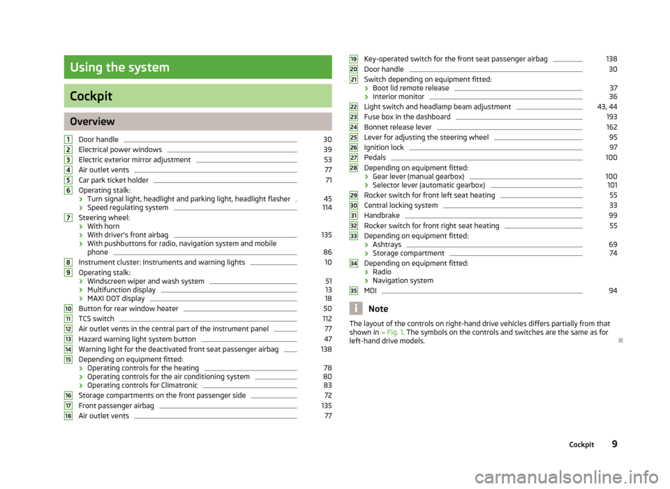
Using the system
Cockpit
OverviewDoor handle
30
Electrical power windows
39
Electric exterior mirror adjustment
53
Air outlet vents
77
Car park ticket holder
71
Operating stalk:
› Turn signal light, headlight and parking light, headlight flasher
45
›
Speed regulating system
114
Steering wheel:
› With horn
› With driver’s front airbag
135
›With pushbuttons for radio, navigation system and mobile
phone
86
Instrument cluster: Instruments and warning lights
10
Operating stalk:
› Windscreen wiper and wash system
51
›Multifunction display
13
›
MAXI DOT display
18
Button for rear window heater
50
TCS switch
112
Air outlet vents in the central part of the instrument panel
77
Hazard warning light system button
47
Warning light for the deactivated front seat passenger airbag
138
Depending on equipment fitted:
› Operating controls for the heating
78
›Operating controls for the air conditioning system
80
›Operating controls for Climatronic
83
Storage compartments on the front passenger side
72
Front passenger airbag
135
Air outlet vents
77123456789101112131415161718Key-operated switch for the front seat passenger airbag138Door handle30
Switch depending on equipment fitted:
› Boot lid remote release
37
›Interior monitor
36
Light switch and headlamp beam adjustment
43, 44
Fuse box in the dashboard
193
Bonnet release lever
162
Lever for adjusting the steering wheel
95
Ignition lock
97
Pedals
100
Depending on equipment fitted:
› Gear lever (manual gearbox)
100
›Selector lever (automatic gearbox)
101
Rocker switch for front left seat heating
55
Central locking system
33
Handbrake
99
Rocker switch for front right seat heating
55
Depending on equipment fitted:
› Ashtrays
69
›Storage compartment
74
Depending on equipment fitted:
› Radio
› Navigation system
MDI
94
Note
The layout of the controls on right-hand drive vehicles differs partially from that
shown in » Fig. 1. The symbols on the controls and switches are the same as for
left-hand drive models.19202122232425262728293031323334359Cockpit
Page 26 of 223
Power steeringFirst read and observe the introductory information and safety warn-
ings
on page 20.
The warning light comes on for a few seconds when the ignition is switched
on.
If the warning light after switching on the ignition or when driving lights up con-
tinuously, a fault exists in the electrohydraulic power steering. The power steer-
ing operates with reduced steering assist or does not function at all.
Seek help from a specialist garage.
Further information » page 95.
Note
■
If the yellow warning light goes out after the engine is restarted and a short
drive, it is not necessary to visit a specialist garage.■
If the vehicle battery has been disconnected and reconnected, the yellow warn-
ing light comes on after switching on the ignition. The warning light should go
out after driving a short distance.
■
There is no power-assisted steering support when the vehicle is being towed
without the engine running or when the power-assisted steering is defect. The vehicle is fully steerable however. There is however increased force required toturn the steering wheel.
Electronic Stability Control (ESC)
First read and observe the introductory information and safety warn-
ings
on page 20.
The warning light flashes
to show that the ESC is currently operating.
If the warning light
comes on immediately after you start the engine, the ESC
might be switched off due to technical reasons. Switch the ignition off and on
again. The ESC is fully functional again if the
warning light does not light up
after you switch the engine back on.
There is a fault in the ESC system if the
warning light lights up.
The following message is shown in the MAXI DOT display.
Fault: Electronic Stability Control (ESC)
Seek help from a specialist garage.
The ESC system cannot be turned off, the » page 112 button only switches the
TCS off, the warning light in the instrument cluster lights up.
As the ESC operates in conjunction with the ABS, the ESP indicator light will also come on if the ABS system fails.
Further information » page 111, Stabilisation control (ESC) .
Note
The warning light comes on after the ignition is switched on if the vehicle's
battery has been disconnected and reconnected. The warning light should go out
after the vehicle has driven a short distance.
Traction Control System (ASR)
First read and observe the introductory information and safety warn-
ings
on page 20.
The warning light flashes
to show that the ASR is currently operating.
If the warning light
comes on immediately after starting the engine, the ASR
can be switched off for technical reasons. Switch the ignition off and on again.
The TCS is fully functional again if the
warning light does not light up after you
switch the engine back on.
If the warning light
lights up, there is a fault in the ASR.
The following message is shown in the MAXI DOT display. Fault: Traction control (TCS)
Seek help from a specialist garage.
The fact that the TCS system operates together with the ABS means that the TCS warning light will also come on if the ABS system is not operating properly.
Further information » page 112, Traction Control System (ASR) .
Note
The
warning light comes on after the ignition is switched on if the vehicle's
battery has been disconnected and reconnected. The warning light should go out
after the vehicle has driven a short distance.
23Instruments and Indicator Lights
Page 47 of 223
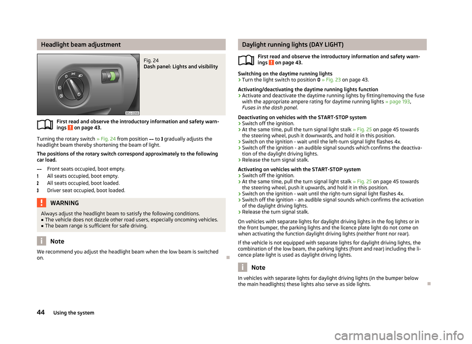
Headlight beam adjustmentFig. 24
Dash panel: Lights and visibility
First read and observe the introductory information and safety warn-
ings on page 43.
Turning the rotary switch » Fig. 24 from position
to
gradually adjusts the
headlight beam thereby shortening the beam of light.
The positions of the rotary switch correspond approximately to the following
car load.
Front seats occupied, boot empty.
All seats occupied, boot empty.
All seats occupied, boot loaded.
Driver seat occupied, boot loaded.
WARNINGAlways adjust the headlight beam to satisfy the following conditions.■The vehicle does not dazzle other road users, especially oncoming vehicles.■
The beam range is sufficient for safe driving.
Note
We recommend you adjust the headlight beam when the low beam is switched
on.
Daylight running lights (DAY LIGHT)
First read and observe the introductory information and safety warn-
ings
on page 43.
Switching on the daytime running lights
›
Turn the light switch to position 0 » Fig. 23 on page 43.
Activating/deactivating the daytime running lights function
›
Activate and deactivate the daytime running lights by fitting/removing the fuse
with the appropriate ampere rating for daytime running lights » page 193,
Fuses in the dash panel .
Deactivating on vehicles with the START-STOP system
›
Switch off the ignition.
›
At the same time, pull the turn signal light stalk » Fig. 25 on page 45 towards
the steering wheel, push it downwards, and hold it in this position.
›
Switch on the ignition - wait until the left-turn signal light flashes 4x.
›
Switch off the ignition - an audible signal sounds which confirms the deactiva- tion of the daylight driving lights.
›
Release the turn signal stalk.
Activating on vehicles with the START-STOP system
›
Switch off the ignition.
›
At the same time, pull the turn signal light stalk » Fig. 25 on page 45 towards
the steering wheel, push it upwards, and hold it in this position.
›
Switch on the ignition - wait until the right-turn signal light flashes 4x.
›
Switch off the ignition - an audible signal sounds which confirms the activation
of the daylight driving lights.
›
Release the turn signal stalk.
On vehicles with separate lights for daylight driving lights in the fog lights or in
the front bumper, the parking lights and the licence plate light do not come on
when activating the function daylight driving lights (neither front nor rear).
If the vehicle is not equipped with separate lights for daylight driving lights, the
combination of the low beam, the parking lights (front and rear) including the li-
cence plate light is used as daylight driving lights.
Note
In vehicles with separate lights for daylight driving lights (in the bumper below
the main headlights) these lights also serve as side lights.
44Using the system
Page 49 of 223
Fog lightsFig. 26
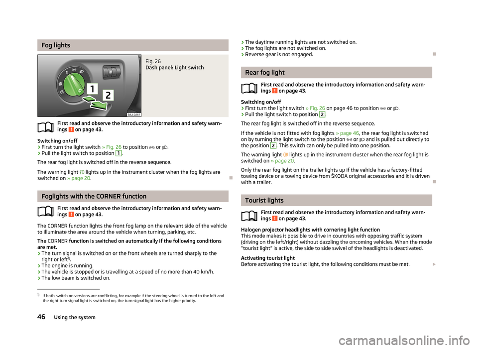
Dash panel: Light switch
First read and observe the introductory information and safety warn-ings on page 43.
Switching on/off
›
First turn the light switch » Fig. 26 to position
or
.
›
Pull the light switch to position
1
.
The rear fog light is switched off in the reverse sequence.
The warning light
lights up in the instrument cluster when the fog lights are
switched on » page 20.
Foglights with the CORNER function
First read and observe the introductory information and safety warn-ings
on page 43.
The CORNER function lights the front fog lamp on the relevant side of the vehicle
to illuminate the area around the vehicle when turning, parking, etc.
The CORNER function is switched on automatically if the following conditions
are met.
› The turn signal is switched on or the front wheels are turned sharply to the
right or left 1)
.
› The engine is running.
› The vehicle is stopped or is travelling at a speed of no more than 40 km/h.
› The low beam is switched on.
›
The daytime running lights are not switched on.
› The fog lights are not switched on.
› Reverse gear is not engaged.
Rear fog light
First read and observe the introductory information and safety warn-
ings
on page 43.
Switching on/off
›
First turn the light switch » Fig. 26 on page 46 to position or .
›
Pull the light switch to position
2
.
The rear fog light is switched off in the reverse sequence.
If the vehicle is not fitted with fog lights » page 46, the rear fog light is switched
on by turning the light switch to the position
or
and is pulled out directly to
the position
2
. This switch can only be pulled into one position.
The warning light
lights up in the instrument cluster when the rear fog light is
switched on » page 20.
Only the rear fog light on the trailer lights up if the vehicle has a factory-fitted
towing device or a towing device from ŠKODA original accessories and it is driven
with a trailer.
Tourist lights
First read and observe the introductory information and safety warn-ings
on page 43.
Halogen projector headlights with cornering light function
This mode makes it possible to drive in countries with opposing traffic system
(driving on the left/right) without dazzling the oncoming vehicles. When the mode
“tourist light” is active, the side to side swivel of the headlights is deactivated.
Activating tourist light
Before activating the tourist light, the following conditions must be met.
1)
If both switch on versions are conflicting, for example if the steering wheel is turned to the left and
the right turn signal light is switched on, the turn signal light has the higher priority.
46Using the system
Page 57 of 223
Seats and storage
Front seats
Introduction
This chapter contains information on the following subjects:
Adjusting the front seats - Version 1
55
Adjusting the front seats - Variant 2
55
Front seat heating
55
The driver's seat should be adjusted in such a way that the pedals can be fully
pressed to the floor with slightly bent legs.
The seat backrest on the driver's seat should be adjusted in such a way that the
upper point of the steering wheel can be easily reached with slightly bent arms.
Correct adjustment of the seats is particularly important:
› for reaching the controls safely and quickly;
› for a relaxed, fatigue-free body position;
› for achieving maximum protection from the seat belts and the airbag system.
WARNINGGeneral information■Caution when adjusting the seat! You may suffer injuries or bruises as a re-
sult of adjusting the seat without paying proper attention.■
The seat backrests must not be reclined too far when driving otherwise this
will affect proper operation of the seat belts and of the airbag system – risk of
injury.
■
Never carry more people than the number of seats in the vehicle.
■
Each occupant must correctly fasten the seat belt belonging to the seat.
Children must be fastened » page 140, Transporting children safely with a
suitable restraint system.
■
The front seats and head restraints must be adjusted to match the body
size at all times and the seat belt must always be fastened properly to provide the most effective levels of protection to the passengers.
■
Do not transport any objects on the front passenger seat other than objects
(e.g. child safety seat) intended for this purpose – there is the risk of an acci-
dent.
WARNINGInformation for the driver■Only adjust the driver's seat when the vehicle is stationary – there is the risk
of an accident.■
Keep a distance of at least 25 cm from the steering wheel. Not keeping to
this minimum distance will mean that the airbag system will not be able to
properly protect you – risk of death.
■
Ensure that there are no objects in the driver's footwell as they may get
caught behind the pedals while you are driving or under braking. You would
then no longer be able to operate the clutch, brake or accelerate.
WARNINGInformation for the front seat passenger■Maintain a distance of at least 25 cm from the dash panel. Not maintaining
this minimum distance will mean that the airbag system will not be able to
properly protect you - there is a risk that you could be killed.■
Always keep your feet in the footwell when the car is being driven - never
place your feet on the instrument panel, out of the window or on the seats.
You will be exposed to increased risk of injury if it becomes necessary to apply
the brakes or in the event of an accident. You may suffer fatal injuries when
an airbag is deployed if you have adopted an incorrect seating position.
Note
After a certain time, play can develop within the adjustment mechanism of the
backrest angle.
54Using the system
Page 58 of 223
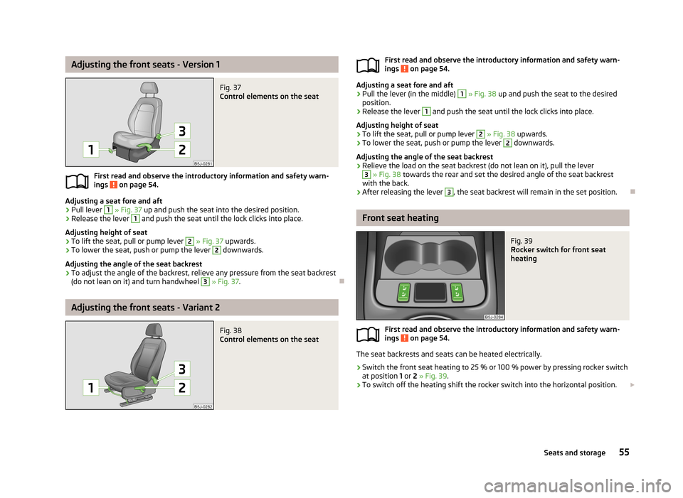
Adjusting the front seats - Version 1Fig. 37
Control elements on the seat
First read and observe the introductory information and safety warn-
ings on page 54.
Adjusting a seat fore and aft
›
Pull lever
1
» Fig. 37 up and push the seat into the desired position.
›
Release the lever
1
and push the seat until the lock clicks into place.
Adjusting height of seat
›
To lift the seat, pull or pump lever
2
» Fig. 37 upwards.
›
To lower the seat, push or pump the lever
2
downwards.
Adjusting the angle of the seat backrest
›
To adjust the angle of the backrest, relieve any pressure from the seat backrest
(do not lean on it) and turn handwheel
3
» Fig. 37 .
Adjusting the front seats - Variant 2
Fig. 38
Control elements on the seatFirst read and observe the introductory information and safety warn-
ings on page 54.
Adjusting a seat fore and aft
›
Pull the lever (in the middle)
1
» Fig. 38 up and push the seat to the desired
position.
›
Release the lever
1
and push the seat until the lock clicks into place.
Adjusting height of seat
›
To lift the seat, pull or pump lever
2
» Fig. 38 upwards.
›
To lower the seat, push or pump the lever
2
downwards.
Adjusting the angle of the seat backrest
›
Relieve the load on the seat backrest (do not lean on it), pull the lever
3
» Fig. 38 towards the rear and set the desired angle of the seat backrest
with the back.
›
After releasing the lever
3
, the seat backrest will remain in the set position.
Front seat heating
Fig. 39
Rocker switch for front seat
heating
First read and observe the introductory information and safety warn-
ings on page 54.
The seat backrests and seats can be heated electrically.
›
Switch the front seat heating to 25 % or 100 % power by pressing rocker switch
at position 1 or 2 » Fig. 39 .
›
To switch off the heating shift the rocker switch into the horizontal position.
55Seats and storage
Page 70 of 223
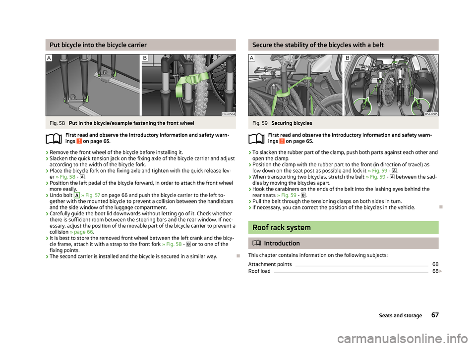
Put bicycle into the bicycle carrierFig. 58
Put in the bicycle/example fastening the front wheel
First read and observe the introductory information and safety warn-
ings
on page 65.
›
Remove the front wheel of the bicycle before installing it.
›
Slacken the quick tension jack on the fixing axle of the bicycle carrier and adjust
according to the width of the bicycle fork.
›
Place the bicycle fork on the fixing axle and tighten with the quick release lev- er » Fig. 58 -
.
›
Position the left pedal of the bicycle forward, in order to attach the front wheel
more easily.
›
Undo bolt
A
» Fig. 57 on page 66 and push the bicycle carrier to the left to-
gether with the mounted bicycle to prevent a collision between the handlebars
and the side window of the luggage compartment.
›
Carefully guide the boot lid downwards without letting go of it. Check whether there is sufficient room between the steering bars and the rear window. If nec-essary, adjust the position of the movable part of the bicycle carrier to prevent a
collision » page 66 .
›
It is best to store the removed front wheel between the left crank and the bicy-
cle frame, attach it with a strap to the front fork » Fig. 58 -
or to one of the
fixing points.
›
The second carrier is installed and the bicycle is secured in a similar way.
Secure the stability of the bicycles with a beltFig. 59
Securing bicycles
First read and observe the introductory information and safety warn-
ings
on page 65.
›
To slacken the rubber part of the clamp, push both parts against each other and
open the clamp.
›
Position the clamp with the rubber part to the front (in direction of travel) as low down on the seat post as possible and lock it » Fig. 59 -
.
›
When transporting two bicycles, stretch the belt » Fig. 59 -
between the sad-
dles by moving the bicycles apart.
›
Hook the carabiners on the ends of the belt into the lashing eyes behind the rear seats » Fig. 59 -
.
›
Pull the belt through the tensioning clasps on both sides in turn.
›
If necessary, you can correct the position of the bicycles in the vehicle.
Roof rack system
Introduction
This chapter contains information on the following subjects:
Attachment points
68
Roof load
68
67Seats and storage
Page 80 of 223
Heating and air conditioning
Heating, ventilation, cooling
Introduction
This chapter contains information on the following subjects:
Air outlets
77
Using the air conditioning system economically
78
Operational problems
78
The heating effect is dependent upon the coolant temperature, thus full heat
output only occurs when the engine has reached its operating temperature.
If the cooling system is switched on, the temperature and air humidity drops in
the vehicle. The cooling system prevents the windows from misting up when out- side temperatures are particularly low.
It is possible to briefly activate recirculated air mode to enhance the cooling ef- fect.
Please refer to the information regarding recirculated air mode for the air-condi- tioning system » page 82 or for Climatronic » page 84.
WARNINGFor your own safety and that of other road users, ensure that all the windows
are free of ice, snow and misting. Please familiarize yourself about how to cor- rectly operate the heating and ventilation systems, how to demist and defrost
the windows, as well as with the cooling mode.
CAUTION
■ The air inlet in front of the windscreen must be free (e.g. of ice, snow or leaves)
to ensure that the heating and cooling system operates properly.■
After switching on the cooling Condensation from the evaporator of the air con-
ditioning may drip down and form a puddle below the vehicle. This is not a leak.
Note■ The exhaust air streams out through vents at the rear of the luggage compart-
ment.■
We recommend that you do not smoke in the vehicle when the recirculating air
mode is operating since the smoke which is drawn at the evaporator from the in- terior of the vehicle forms deposits in the evaporator of the air conditioning sys-tem. This produces a permanent odour when the air conditioning system is oper-ating which can only be eliminated through considerable effort and expense (re-
placement of compressor).
Air outlets
Fig. 77
Air outlet vents
First read and observe the introductory information and safety warn- ings
on page 77.
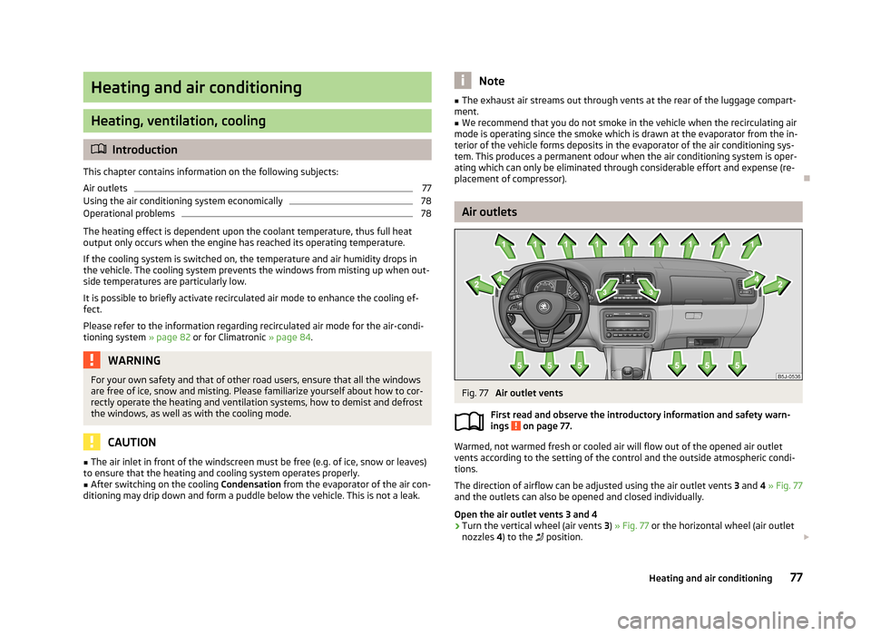
Warmed, not warmed fresh or cooled air will flow out of the opened air outlet
vents according to the setting of the control and the outside atmospheric condi-
tions.
The direction of airflow can be adjusted using the air outlet vents 3 and 4 » Fig. 77
and the outlets can also be opened and closed individually.
Open the air outlet vents 3 and 4
›
Turn the vertical wheel (air vents 3) » Fig. 77 or the horizontal wheel (air outlet
nozzles 4) to the
position.
77Heating and air conditioning
Page 81 of 223
Close air outlet vents 3 and 4›Turn the vertical wheel (air vents 3) » Fig. 77 or the horizontal wheel (air outlet
nozzles 4) to the 0 position.
Change air flow of air outlet vents 3 and 4›
In order to change the strength of the air flow, swivel the horizontal lamellas with the aid of the moveable adjuster » Fig. 77.
›
In order to change the lateral direction of the air flow, swivel the vertical lamel-
las with the aid of the moveable adjuster.
Set the air supply to the individual vents with the air distribution control
C
» Fig. 78 on page 79.
Note
Do not cover the air outlet vents with objects of any kind.
Using the air conditioning system economically
First read and observe the introductory information and safety warn-ings
on page 77.
The air conditioning system compressor uses power from the engine when in
cooling mode, which will affect the fuel consumption.
It recommended to open the windows or the doors of a vehicle for which the inte-rior has been strongly heated through the effect of direct sunlight in order to al-
low the heated air to escape.
The cooling system should not be switched on if the windows are open.
For the sake of the environment
Pollutant emissions are also lower when fuel is being saved » page 104.
Operational problems
First read and observe the introductory information and safety warn-
ings
on page 77.
If the cooling system does not operate at outside temperatures higher than +5 °C,
there is a problem in the system. The reasons for this may be.
› One of the fuses has blown. Check the fuse and replace if necessa-
ry » page 192 .
› The cooling system has switched off automatically for a short time because the
coolant temperature of the engine is too hot » page 11.
If you are not able to resolve the fault yourself, or if the cooling output has re- duced, switch off the cooling system and obtain assistance from a specialist ga-
rage.
Heating
Introduction
This chapter contains information on the following subjects:
Operation
79
Setting
79
Recirculated air mode
80
78Using the system