seats SKODA FABIA 2013 2.G / 5J User Guide
[x] Cancel search | Manufacturer: SKODA, Model Year: 2013, Model line: FABIA, Model: SKODA FABIA 2013 2.G / 5JPages: 223, PDF Size: 12.77 MB
Page 64 of 223
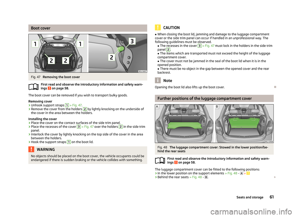
Boot coverFig. 47
Removing the boot cover
First read and observe the introductory information and safety warn-
ings
on page 58.
The boot cover can be removed if you wish to transport bulky goods.
Removing cover
›
Unhook support straps
1
» Fig. 47 .
›
Remove the cover from the holders
2
by lightly knocking on the underside of
the cover in the area between the holders.
Installing the cover
›
Place the cover on the contact surfaces of the side trim panel.
›
Place the recesses of the cover
3
» Fig. 47 over the holders
2
in the side trim
panel.
›
Interlock the cover by lightly knocking on the top side of the cover in the area
between the holders.
›
Hook the support straps
1
on the boot lid.
WARNINGNo objects should be placed on the boot cover, the vehicle occupants could beendangered if there is sudden braking or the vehicle collides with something.CAUTION■ When closing the boot lid, jamming and damage to the luggage compartment
cover or the side trim panel can occur if handled in an unprofessional way. The
following guidelines must be observed. ■The recesses in the cover 3
» Fig. 47 must lock in the holders in the side trim
panel
2
.
■ The items which are transported must not exceed the height of the luggage
compartment cover. ■ The cover must not be jammed in the seal of the boot lid when it is in the
opened position. ■ There must be no object in the gap between the opened cover and the rear
backrest.
Note
Opening the boot lid also lifts up the boot cover.
Further positions of the luggage compartment cover
Fig. 48
The luggage compartment cover: Stowed in the lower position/be-
hind the rear seats
First read and observe the introductory information and safety warn-
ings
on page 58.
The luggage compartment cover can be fitted to the following positions:
› In the lower position on the support elements
» Fig. 48 -
»
› Behind the rear seats
» Fig. 48 -
.
61Seats and storage
Page 66 of 223
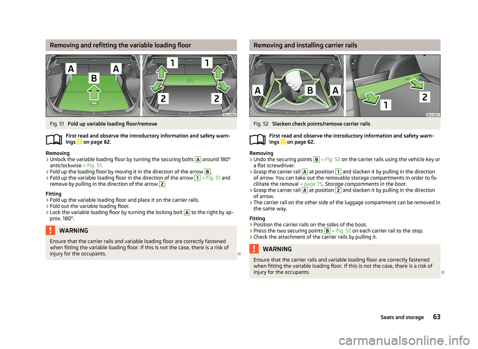
Removing and refitting the variable loading floorFig. 51
Fold up variable loading floor/remove
First read and observe the introductory information and safety warn-
ings
on page 62.
Removing
›
Unlock the variable loading floor by turning the securing bolts
A
around 180°
anticlockwise » Fig. 51.
›
Fold up the loading floor by moving it in the direction of the arrow
B
.
›
Fold up the variable loading floor in the direction of the arrow
1
» Fig. 51 and
remove by pulling in the direction of the arrow
2
Fitting
›
Fold up the variable loading floor and place it on the carrier rails.
›
Fold out the variable loading floor.
›
Lock the variable loading floor by turning the locking bolt
A
to the right by ap-
prox. 180°.
WARNINGEnsure that the carrier rails and variable loading floor are correctly fastened
when fitting the variable loading floor. If this is not the case, there is a risk of
injury for the occupants.
Removing and installing carrier railsFig. 52
Slacken check points/remove carrier rails
First read and observe the introductory information and safety warn- ings
on page 62.
Removing
›
Undo the securing points
B
» Fig. 52 on the carrier rails using the vehicle key or
a flat screwdriver.
›
Grasp the carrier rail
A
at position
1
and slacken it by pulling in the direction
of arrow. You can take out the removable storage compartments in order to fa-
cilitate the removal » page 75, Storage compartments in the boot .
›
Grasp the carrier rail
A
at position
2
and slacken it by pulling in the direction
of arrow.
›
The carrier rail on the other side of the luggage compartment can be removed in
the same way.
Fitting
›
Position the carrier rails on the sides of the boot.
›
Press the two securing points
B
» Fig. 52 on each carrier rail to the stop.
›
Check the attachment of the carrier rails by pulling it.
WARNINGEnsure that the carrier rails and variable loading floor are correctly fastened
when fitting the variable loading floor. If this is not the case, there is a risk of
injury for the occupants.
63Seats and storage
Page 67 of 223
Net partition (Fabia Estate)
Introduction
This chapter contains information on the following subjects:
Using the net partition behind the rear seats
64
Using the net partition behind the front seats
65
Removing and refitting the net partition housing
65WARNING■ The belt locks and the belts must be in their original position after folding
back the seat cushions and backrests - they must be ready to use.■
The seat backrests must be securely latched in position so that no objects
from the luggage compartment can slip into the passenger compartment un- der sudden braking – there is a risk of injury.
■
Ensure that the rear seat backrests are properly engaged. It is only then that
the three-point seat belt for the middle seat can reliably fulfil its function.
■
Make sure that the transverse rod is inserted into the mounts
C
» Fig. 53
on page 64 or » Fig. 54 on page 65 in the forward position.
Using the net partition behind the rear seats
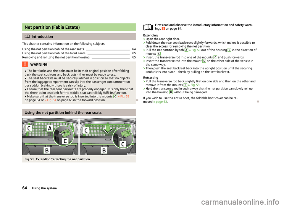
Fig. 53
Extending/retracting the net partition
First read and observe the introductory information and safety warn-
ings on page 64.
Extending
›
Open the rear right door.
›
Fold down the rear seat backrests slightly forwards, which makes it possible to
clear the access for removing the net partition.
›
Pull the net partition by tab
A
» Fig. 53 out of the housing
B
in the direction of
mounts
C
.
›
Insert the transverse rod into one of the mounts
C
and push forwards.
›
Insert the transverse rod into the mount
C
on the other side of the vehicle in
the same way.
›
Then push the seat backrest back into the upright position until the securing
knob clicks into place - check by pulling on the seat backrest.
Retracting
›
Pull the transverse rod back slightly first on one side and then on the other and
remove it from the mounts
C
» Fig. 53 .
›
Hold the transverse rod in such a way that the net partition can slowly roll up
into the housing
B
without being damaged.
If you wish to use the entire boot, the foldable boot cover can be re- moved » page 62 .
64Using the system
Page 68 of 223
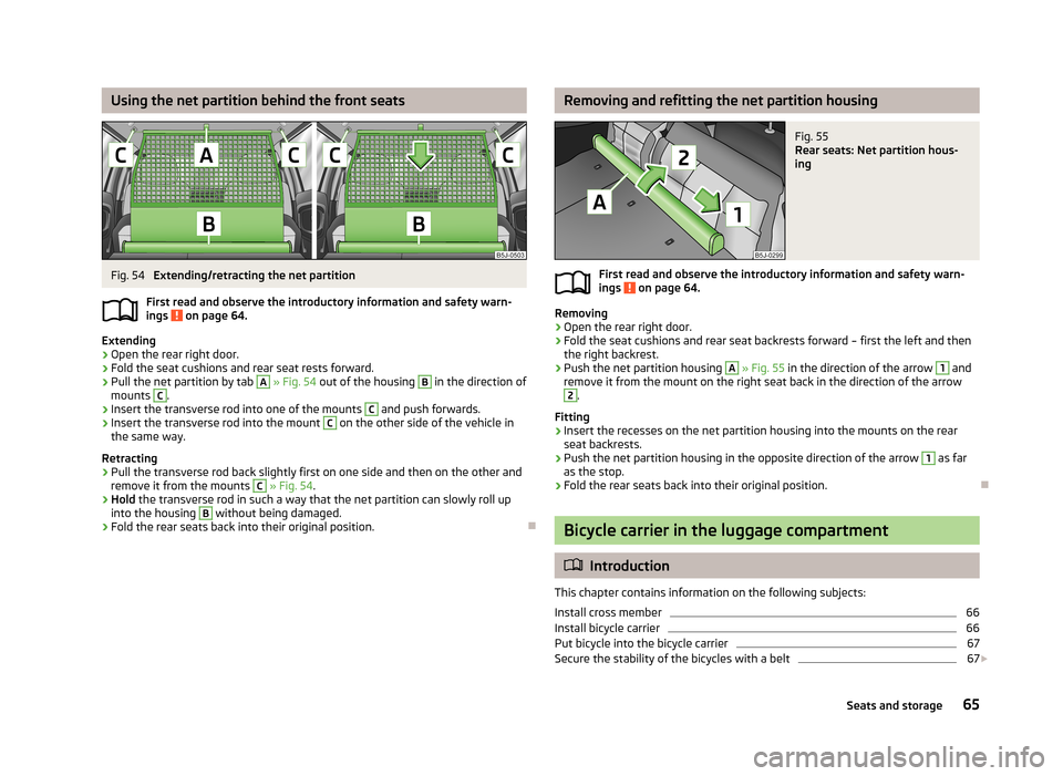
Using the net partition behind the front seatsFig. 54
Extending/retracting the net partition
First read and observe the introductory information and safety warn- ings
on page 64.
Extending
›
Open the rear right door.
›
Fold the seat cushions and rear seat rests forward.
›
Pull the net partition by tab
A
» Fig. 54 out of the housing
B
in the direction of
mounts
C
.
›
Insert the transverse rod into one of the mounts
C
and push forwards.
›
Insert the transverse rod into the mount
C
on the other side of the vehicle in
the same way.
Retracting
›
Pull the transverse rod back slightly first on one side and then on the other and
remove it from the mounts
C
» Fig. 54 .
›
Hold the transverse rod in such a way that the net partition can slowly roll up
into the housing
B
without being damaged.
›
Fold the rear seats back into their original position.
Removing and refitting the net partition housingFig. 55
Rear seats: Net partition hous-
ing
First read and observe the introductory information and safety warn-
ings on page 64.
Removing
›
Open the rear right door.
›
Fold the seat cushions and rear seat backrests forward – first the left and then the right backrest.
›
Push the net partition housing
A
» Fig. 55 in the direction of the arrow
1
and
remove it from the mount on the right seat back in the direction of the arrow
2
.
Fitting
›
Insert the recesses on the net partition housing into the mounts on the rear seat backrests.
›
Push the net partition housing in the opposite direction of the arrow
1
as far
as the stop.
›
Fold the rear seats back into their original position.
Bicycle carrier in the luggage compartment
Introduction
This chapter contains information on the following subjects:
Install cross member
66
Install bicycle carrier
66
Put bicycle into the bicycle carrier
67
Secure the stability of the bicycles with a belt
67
65Seats and storage
Page 69 of 223
WARNINGWhen transporting bicycles, ensuring the safety of the passengers is para-
mount.
CAUTION
Take care handling the bicycle - there is a risk of damaging the vehicle.
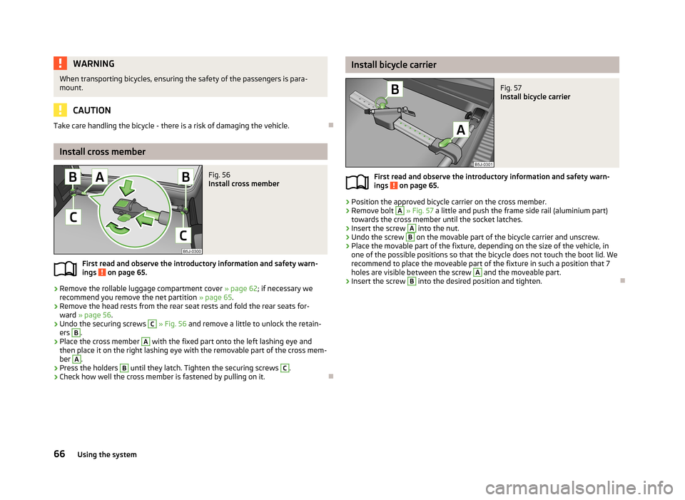
Install cross member
Fig. 56
Install cross member
First read and observe the introductory information and safety warn- ings on page 65.
›
Remove the rollable luggage compartment cover » page 62; if necessary we
recommend you remove the net partition » page 65.
›
Remove the head rests from the rear seat rests and fold the rear seats for-
ward » page 56 .
›
Undo the securing screws
C
» Fig. 56 and remove a little to unlock the retain-
ers
B
.
›
Place the cross member
A
with the fixed part onto the left lashing eye and
then place it on the right lashing eye with the removable part of the cross mem-
ber
A
.
›
Press the holders
B
until they latch. Tighten the securing screws
C
.
›
Check how well the cross member is fastened by pulling on it.
Install bicycle carrierFig. 57
Install bicycle carrier
First read and observe the introductory information and safety warn- ings on page 65.
›
Position the approved bicycle carrier on the cross member.
›
Remove bolt
A
» Fig. 57 a little and push the frame side rail (aluminium part)
towards the cross member until the socket latches.
›
Insert the screw
A
into the nut.
›
Undo the screw
B
on the movable part of the bicycle carrier and unscrew.
›
Place the movable part of the fixture, depending on the size of the vehicle, in
one of the possible positions so that the bicycle does not touch the boot lid. We
recommend to place the moveable part of the fixture in such a position that 7 holes are visible between the screw
A
and the moveable part.
›
Insert the screw
B
into the desired position and tighten.
66Using the system
Page 70 of 223
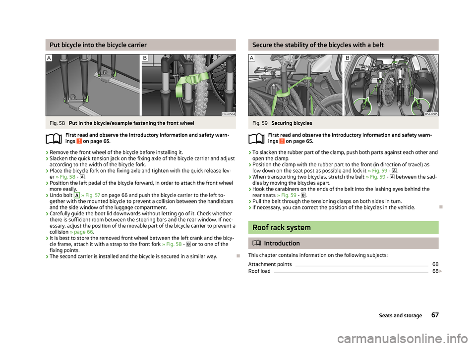
Put bicycle into the bicycle carrierFig. 58
Put in the bicycle/example fastening the front wheel
First read and observe the introductory information and safety warn-
ings
on page 65.
›
Remove the front wheel of the bicycle before installing it.
›
Slacken the quick tension jack on the fixing axle of the bicycle carrier and adjust
according to the width of the bicycle fork.
›
Place the bicycle fork on the fixing axle and tighten with the quick release lev- er » Fig. 58 -
.
›
Position the left pedal of the bicycle forward, in order to attach the front wheel
more easily.
›
Undo bolt
A
» Fig. 57 on page 66 and push the bicycle carrier to the left to-
gether with the mounted bicycle to prevent a collision between the handlebars
and the side window of the luggage compartment.
›
Carefully guide the boot lid downwards without letting go of it. Check whether there is sufficient room between the steering bars and the rear window. If nec-essary, adjust the position of the movable part of the bicycle carrier to prevent a
collision » page 66 .
›
It is best to store the removed front wheel between the left crank and the bicy-
cle frame, attach it with a strap to the front fork » Fig. 58 -
or to one of the
fixing points.
›
The second carrier is installed and the bicycle is secured in a similar way.
Secure the stability of the bicycles with a beltFig. 59
Securing bicycles
First read and observe the introductory information and safety warn-
ings
on page 65.
›
To slacken the rubber part of the clamp, push both parts against each other and
open the clamp.
›
Position the clamp with the rubber part to the front (in direction of travel) as low down on the seat post as possible and lock it » Fig. 59 -
.
›
When transporting two bicycles, stretch the belt » Fig. 59 -
between the sad-
dles by moving the bicycles apart.
›
Hook the carabiners on the ends of the belt into the lashing eyes behind the rear seats » Fig. 59 -
.
›
Pull the belt through the tensioning clasps on both sides in turn.
›
If necessary, you can correct the position of the bicycles in the vehicle.
Roof rack system
Introduction
This chapter contains information on the following subjects:
Attachment points
68
Roof load
68
67Seats and storage
Page 72 of 223
Useful equipment
Introduction
This chapter contains information on the following subjects:
Cupholders
69
Ashtray
69
Cigarette lighter
70
12-volt power outlet
70
Clothes hook
71
Car park ticket holder
71WARNING■ Do not place anything on the dash panel. These objects might slide or fall
down while you are driving (under acceleration or when cornering) and could
distract you from the traffic - there is a risk of an accident.■
Make sure that no objects from the centre console or from other storage
compartments can get into the driver's footwell while you are driving. You
would then no longer be able to apply the brakes or operate the clutch or ac-
celerator pedal – there is a risk of an accident.
■
Ash and cigarette or cigar stubs must only be discarded in ashtrays.
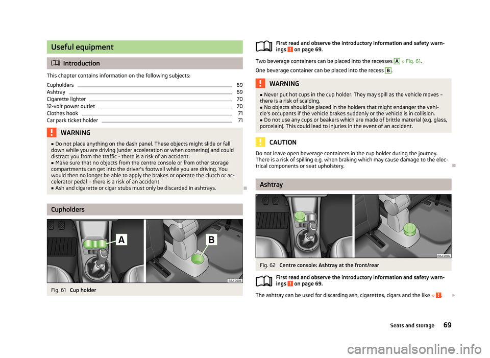
Cupholders
Fig. 61
Cup holder
First read and observe the introductory information and safety warn-
ings on page 69.
Two beverage containers can be placed into the recesses
A
» Fig. 61 .
One beverage container can be placed into the recess
B
.
WARNING■ Never put hot cups in the cup holder. They may spill as the vehicle moves –
there is a risk of scalding.■
No objects should be placed in the holders that might endanger the vehi-
cle's occupants if the vehicle brakes suddenly or the vehicle is in collision.
■
Do not use any cups or beakers which are made of brittle material (e.g. glass,
porcelain). This could lead to injuries in the event of an accident.
CAUTION
Do not leave open beverage containers in the cup holder during the journey.
There is a risk of spilling e.g. when braking which may cause damage to the elec-
trical components or seat upholstery.
Ashtray
Fig. 62
Centre console: Ashtray at the front/rear
First read and observe the introductory information and safety warn-
ings
on page 69.
The ashtray can be used for discarding ash, cigarettes, cigars and the like » .
69Seats and storage
Page 74 of 223
WARNING■Improper use of the 12-volt power socket and the electrical accessories can
cause fires, burns and other serious injuries.■
Never leave children unattended in the vehicle. The 12-volt power socket
and any connected appliances can also be operated when the ignition is switched off or the ignition key is withdrawn.
■
If the connected electric device becomes too hot, switch it off and discon-
nect it from the power supply immediately.
CAUTION
■ The 12-volt power socket can only be used for connecting approved electrical
accessories with a total power uptake of up to 120 watt.■
Never exceed the maximum power consumption, otherwise the vehicle's elec-
trical system can be damaged.
■
Connecting electrical components when the engine is not running will drain the
battery of the vehicle – there is a risk of the battery discharging.
■
Only use matching plugs to avoid damaging the 12-volt power socket.
■
Only use accessories that have been tested for electromagnetic compatibility in
accordance with the applicable directives.
■
Before turning the ignition on or off, and before starting the car, switch off the
device connected to the 12-volt power socket to prevent any damage caused by
voltage fluctuations.
■
Observe the operating instructions for the connected devices!
Clothes hook
First read and observe the introductory information and safety warn-ings
on page 69.
The clothes hooks are located on the handle of the headliner above each of the
rear doors.
WARNING■ Ensure that any clothes hanging from the hooks do not impair your vision to
the rear.■
Only use the hooks for hanging light items of clothing and ensure that there
are no heavy or sharp-edged objects in the pockets.
■
Do not use clothes hangers for hanging up items of clothing otherwise this
may reduce the effectiveness of head airbags.
CAUTION
The maximum permissible load of the hooks is 2 kg.
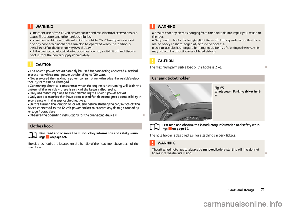
Car park ticket holder
Fig. 65
Windscreen: Parking ticket hold-
er
First read and observe the introductory information and safety warn-
ings on page 69.
The note holder is designed e.g. for attaching car park tickets.
WARNINGThe attached note has to always be removed before starting off in order not
to restrict the driver's vision.
71Seats and storage
Page 75 of 223
Storage compartments
Introduction
This chapter contains information on the following subjects:
Storage compartments on the front passenger side
72
Cooling the storage compartment on the front passenger side
73
Storage compartment on the driver's side
73
Map pockets in the front seats
73
Glasses storage box
74
Stowage compartment in centre console
74
Stowage compartment underneath the front passenger seat
74
Front armrest with storage compartment
75
Storage compartments in the doors
75
Storage compartments in the boot
75
Flexible storage compartment
76WARNING■ Do not place anything on the dash panel. These objects might slide or fall
down while you are driving (under acceleration or when cornering) and could
distract you from the traffic - there is a risk of an accident.■
Make sure that no objects from the centre console or from other storage
compartments can get into the driver's footwell while you are driving. You
would then no longer be able to apply the brakes or operate the clutch or ac-
celerator pedal – there is a risk of an accident.
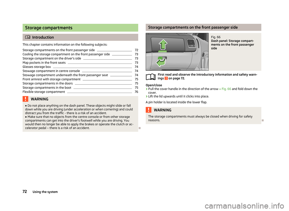
Storage compartments on the front passenger sideFig. 66
Dash panel: Storage compart-
ments on the front passenger
side
First read and observe the introductory information and safety warn-
ings on page 72.
Open/close
›
Pull the cover handle in the direction of the arrow » Fig. 66 and fold down the
cover.
›
Lift the lid upwards until it clicks into place.
A pin holder is located inside the lower flap.
WARNINGThe storage compartments must always be closed when driving for safety
reasons.
72Using the system
Page 76 of 223
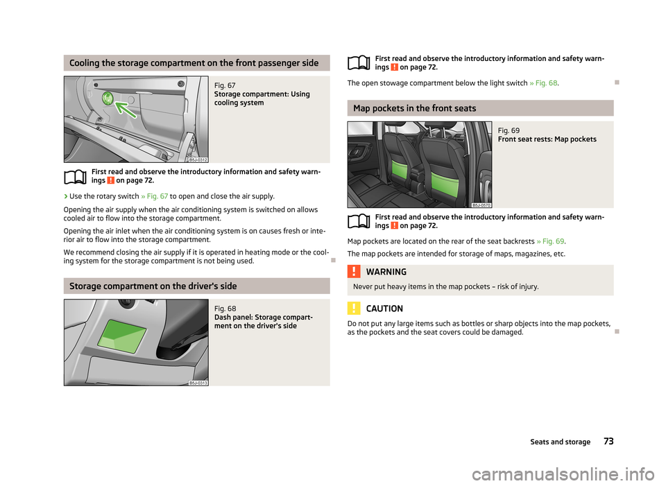
Cooling the storage compartment on the front passenger sideFig. 67
Storage compartment: Using
cooling system
First read and observe the introductory information and safety warn-
ings on page 72.
›
Use the rotary switch » Fig. 67 to open and close the air supply.
Opening the air supply when the air conditioning system is switched on allows
cooled air to flow into the storage compartment.
Opening the air inlet when the air conditioning system is on causes fresh or inte-rior air to flow into the storage compartment.
We recommend closing the air supply if it is operated in heating mode or the cool-ing system for the storage compartment is not being used.
Storage compartment on the driver's side
Fig. 68
Dash panel: Storage compart-
ment on the driver's sideFirst read and observe the introductory information and safety warn-
ings on page 72.
The open stowage compartment below the light switch » Fig. 68.
Map pockets in the front seats
Fig. 69
Front seat rests: Map pockets
First read and observe the introductory information and safety warn-
ings on page 72.
Map pockets are located on the rear of the seat backrests » Fig. 69.
The map pockets are intended for storage of maps, magazines, etc.
WARNINGNever put heavy items in the map pockets – risk of injury.
CAUTION
Do not put any large items such as bottles or sharp objects into the map pockets,
as the pockets and the seat covers could be damaged.
73Seats and storage