lock SKODA FABIA 2013 2.G / 5J Service Manual
[x] Cancel search | Manufacturer: SKODA, Model Year: 2013, Model line: FABIA, Model: SKODA FABIA 2013 2.G / 5JPages: 223, PDF Size: 12.77 MB
Page 103 of 223
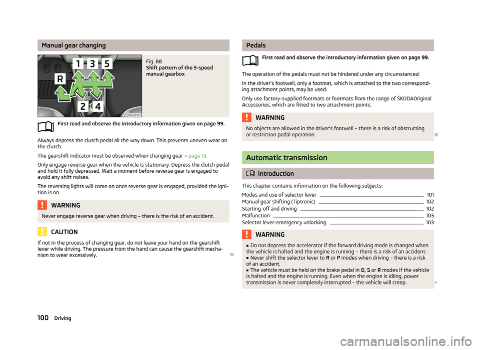
Manual gear changingFig. 88
Shift pattern of the 5-speed
manual gearbox
First read and observe the introductory information given on page 99.
Always depress the clutch pedal all the way down. This prevents uneven wear on the clutch.
The gearshift indicator must be observed when changing gear » page 13.
Only engage reverse gear when the vehicle is stationary. Depress the clutch pedal
and hold it fully depressed. Wait a moment before reverse gear is engaged to
avoid any shift noises.
The reversing lights will come on once reverse gear is engaged, provided the igni- tion is on.
WARNINGNever engage reverse gear when driving – there is the risk of an accident.
CAUTION
If not in the process of changing gear, do not leave your hand on the gearshiftlever while driving. The pressure from the hand can cause the gearshift mecha-
nism to wear excessively.
Pedals
First read and observe the introductory information given on page 99.
The operation of the pedals must not be hindered under any circumstances!
In the driver's footwell, only a footmat, which is attached to the two correspond- ing attachment points, may be used.
Only use factory-supplied footmats or footmats from the range of ŠKODAOriginal Accessories, which are fitted to two attachment points.
WARNINGNo objects are allowed in the driver's footwell – there is a risk of obstructing
or restriction pedal operation.
Automatic transmission
Introduction
This chapter contains information on the following subjects:
Modes and use of selector lever
101
Manual gear shifting (Tiptronic)
102
Starting-off and driving
102
Malfunction
103
Selector lever-emergency unlocking
103WARNING■ Do not depress the accelerator if the forward driving mode is changed when
the vehicle is halted and the engine is running – there is a risk of an accident.■
Never shift the selector lever to R or P modes when driving – there is a risk
of an accident.
■
The vehicle must be held on the brake pedal in D, S or R modes if the vehicle
is halted and the engine is running. Even when the engine is idling, power
transmission is never completely interrupted – the vehicle will creep.
100Driving
Page 104 of 223
CAUTION■If the selector lever is shifted to N while the vehicle is being driven you must lift
off the accelerator pedal and you will need to wait until the engine has reached
its idling speed before shifting the selector lever to a forward driving mode again.■
At temperatures below -10 °C, the engine can only be started in selector lever
position P.
■
Never try to hold the vehicle using the accelerator pedal when stopping on a hill
– this may lead to transmission damage.
Note
The ignition key can only be withdrawn once the ignition has been switched off if
the selector lever is in the P position 1)
.
Modes and use of selector lever
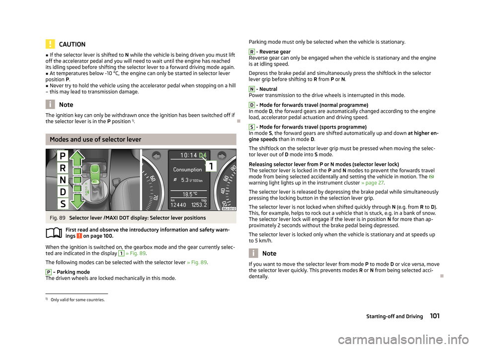
Fig. 89
Selector lever /MAXI DOT display: Selector lever positions
First read and observe the introductory information and safety warn-
ings
on page 100.
When the ignition is switched on, the gearbox mode and the gear currently selec-
ted are indicated in the display
1
» Fig. 89 .
The following modes can be selected with the selector lever » Fig. 89.
P
– Parking mode
The driven wheels are locked mechanically in this mode.
Parking mode must only be selected when the vehicle is stationary.R
- Reverse gear
Reverse gear can only be engaged when the vehicle is stationary and the engine
is at idling speed.
Depress the brake pedal and simultaneously press the shiftlock in the selector
lever grip before shifting to R from P or N.
N
- Neutral
Power transmission to the drive wheels is interrupted in this mode.
D
- Mode for forwards travel (normal programme)
In mode D, the forward gears are automatically changed according to the engine
load, accelerator pedal actuation and driving speed.
S
- Mode for forwards travel (sports programme)
In mode S, the forward gears are shifted automatically up and down at higher en-
gine speeds than in mode D.
The shiftlock on the selector lever grip must be pressed when moving the selec-
tor lever out of D mode into S mode.
Releasing selector lever from P or N modes (selector lever lock) The selector lever is locked in the P and N modes to prevent the forwards travel
mode from being selected accidentally and setting the vehicle in motion. The
warning light lights up in the instrument cluster » page 27.
The selector lever is released by depressing the brake pedal while simultaneously
pressing the locking button in the selection lever grip.
The selector lever is not locked when shifted quickly through N (e.g. from R to D).
This, for example, helps to rock out a vehicle that is stuck, e.g. in a bank of snow.
The selector lever lock will engage if the lever is in position N for more than ap-
proximately 2 seconds without the brake pedal being depressed.
The selector lever is locked only when the vehicle is stationary and at speeds up to 5 km/h.
Note
If you want to move the selector lever from mode P
to mode D or vice versa, move
the selector lever quickly. This prevents modes R or N from being selected acci-
dentally.1)
Only valid for some countries.
101Starting-off and Driving
Page 105 of 223
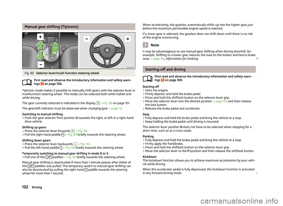
Manual gear shifting (Tiptronic)Fig. 90
Selector lever/multi-function steering wheel
First read and observe the introductory information and safety warn- ings
on page 100.
Tiptronic mode makes it possible to manually shift gears with the selector lever or
multifunction steering wheel. This mode can be selected both while halted and
while driving.
The gear currently selected is indicated in the display
1
» Fig. 89 on page 101.
The gearshift indicator must be observed when changing gear » page 13.
Switching to manual shifting
›
Push the gear selector from position D towards the right, or left in a right-hand
drive vehicle.
Shifting up gears
›
Press the selector lever forwards
+
» Fig. 90 .
›
Pull the right-hand paddle +
» Fig. 90 briefly towards the steering wheel.
Shifting down gears
›
Press the selector lever backwards
-
» Fig. 90 .
›
Pull the left-hand paddle -
» Fig. 90 briefly towards the steering wheel.
Temporarily switching to manual gear shifting in mode D or S
›
Pull one of the -/+ paddles
» Fig. 90 briefly towards the steering wheel .
Manual gear shifting is deactivated if more than 1 minute passes after either of
the -
/+ paddles was pulled. The temporary switch to manual gear shifting can
also be deactivated by pulling the right-hand + paddle towards the steering
wheel for more than 1 second.
When accelerating, the gearbox automatically shifts up into the higher gear just
before the maximum permissible engine speed is reached.
If a lower gear is selected, the gearbox does not shift down until there is no riskof the engine overrevving.
Note
It may be advantageous to use manual gear shifting when driving downhill, for
example. Shifting to a lower gear reduces the load on the brakes and hence brake wear » page 98 , Information for braking .
Starting-off and driving
First read and observe the introductory information and safety warn-
ings
on page 100.
Starting off
›
Start the engine.
›
Firmly depress and hold the brake pedal.
›
Press and hold the shiftlock button on the selector lever grip.
›
Move the selector lever into the desired position » page 101 and then release
the lock button.
›
Release the brake pedal and accelerate.
Stop
›
Fully depress and hold the brake pedal and bring the vehicle to a stop.
›
Keep holding the brake pedal until driving is resumed.
The selector lever position N does not have to be selected when stopping for a
short time, such as at a cross roads.
Parking
›
Fully depress and hold the brake pedal and bring the vehicle to a stop.
›
Firmly apply the handbrake.
›
Press and hold the shiftlock button on the selector lever grip.
›
Move the selector lever to the P position and then release the shiftlock button.
Kickdown
The kickdown function allows you to achieve maximum acceleration by your vehi-
cle while driving.
When the accelerator pedal is fully depressed, the kickdown function is activated
in any forward driving mode.
102Driving
Page 106 of 223
The gearbox shifts down one or more gears depending on the vehicle speed andengine speed, and the vehicle accelerates.
The gearbox does not shift up into the highest gear until the engine has reached
its maximum revolutions for this gear range.WARNINGRapid acceleration, particularly on slippery roads, can lead to loss of control of
the vehicle – there is a risk of an accident.
Malfunction
First read and observe the introductory information and safety warn-
ings
on page 100.
Emergency programme
The transmission switches to the emergency programme if there is a fault in the
automatic gearbox system.
Indications of an activated emergency programme include the following:
› Only certain gears are selected.
› Reverse gear
R cannot be used.
› Shifting gears in Tiptronic mode is not possible.
Gearbox overheating
The gearbox may, for example, become too hot due to frequent repeated starting
or stop-and-go traffic. Overheating is indicated by the warning light » page 19,
Clutches in the automatic gearbox are too hot .
Note
Visit a specialist workshop if the gearbox has switched to the emergency pro-
gramme.
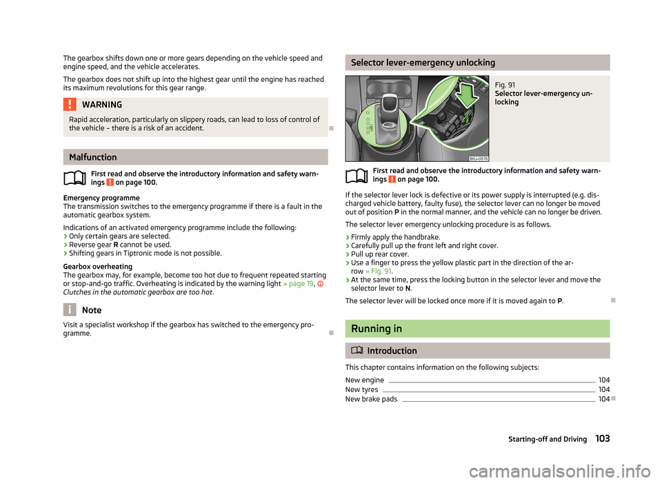
Selector lever-emergency unlockingFig. 91
Selector lever-emergency un-
locking
First read and observe the introductory information and safety warn-
ings on page 100.
If the selector lever lock is defective or its power supply is interrupted (e.g. dis-
charged vehicle battery, faulty fuse), the selector lever can no longer be moved
out of position P in the normal manner, and the vehicle can no longer be driven.
The selector lever emergency unlocking procedure is as follows.
›
Firmly apply the handbrake.
›
Carefully pull up the front left and right cover.
›
Pull up rear cover.
›
Use a finger to press the yellow plastic part in the direction of the ar- row » Fig. 91 .
›
At the same time, press the locking button in the selector lever and move the
selector lever to N.
The selector lever will be locked once more if it is moved again to P.
Running in
Introduction
This chapter contains information on the following subjects:
New engine
104
New tyres
104
New brake pads
104
103Starting-off and Driving
Page 114 of 223
Assist systems
Brake assist systems
Introduction
This chapter contains information on the following subjects:
Stabilisation control (ESC)
111
Antilock Braking System (ABS)
112
Traction Control System (ASR)
112
Electronic Differential Lock (EDL and XDS)
112WARNING■ A lack of fuel can cause irregular engine running or cause the engine to shut
down. The brake assist systems would then be without function – there is the
risk of an accident.■
Adjust the speed and driving style to the current visibility, weather, road and
traffic conditions. The increased safety offered by the brake assist systems
must not tempt you to take greater risks than otherwise – there is the risk of
an accident.
■
Visit a specialist garage immediately in the event of an ABS fault. Adjust
your style of driving according to the damage to the ABS as you will not know
how great the damage is and the limitation it is placing on the braking effi-
ciency.
CAUTION
■ All four wheels must be fitted with the same tyres approved by the manufactur-
er to ensure the brake assist systems operate correctly.■
Changes to the vehicle (e.g. to the engine, brakes, chassis) can influence the
functionality of the brake assist systems » page 147, Services, modifications and
technical alterations .
■
If a fault occurs in the ABS system, the ESC, TCS and EDL will also fail to work.
An ABS fault is indicated with by the warning light » page 24.
Stabilisation control (ESC)
First read and observe the introductory information and safety warn-ings
on page 111.
The ESC system helps to maintain control of the vehicle in situations where it is
being operated at its dynamic limits, such as a sudden change to the direction of
travel. Depending on the road surface conditions, the risk of skidding is reduced,
thereby improving the vehicle's driving stability .
The ESC system is automatically activated each time the ignition is switched on.
The direction which the driver wishes to take is determined based on the steering angle and the speed of the vehicle and is constantly compared with the actual
behaviour of the vehicle. If differences exist, such as the car beginning to skid,
the ESC system will automatically brake the appropriate wheel.
During an intervention of the system, the warning light
flashes in the instru-
ment cluster.
The following systems are integrated into the electronic stabilisation control
(ESC) :
› Antilock brake system (ABS),
› Traction control (TCS),
› Electronic Differential Lock (EDL and XDS);
› Hydraulic brake assist (HBA);
› Hill hold control (HHC).
The ESC system cannot be deactivated. The
» Fig. 96 on page 112 button can
only be used to deactivate the TCS. The
warning light comes on in the instru-
ment cluster when the TCS is deactivated.
In the event of an ESC fault, the ESC warning light illuminates in the instrument cluster
» page 23 .
Hydraulic brake assist (HBA)
HBA increases the braking effect and helps to shorten the braking distance.
The HBA is activated by very rapid depression of the brake pedal. To achieve the
shortest possible braking distance, the brake pedal must be applied firmly until
the vehicle has come to a complete standstill.
HBA is automatically switched off when the brake pedal is released. ABS is activated sooner and more effectively with the intervention of HBA.
111Assist systems
Page 115 of 223
Hill hold control (HHC)
HHC allows you to move your foot from the brake pedal to the accelerator pedal
without having to use the handbrake when pulling away on a gradient.
The system holds the brake pressure produced by the activation of the brake
pedal for approx. 2 seconds after the brake pedal is released.
The brake pressure drops gradually the more you operate the accelerator pedal. Ifthe vehicle does not start off within 2 seconds, it starts to roll back.
HHC is active on slopes of >5 % when the driver door is closed. HHC is always only
active on slopes pulling away forwards or in reverse. When driving downhill, it is inactive.
Antilock Braking System (ABS)
First read and observe the introductory information and safety warn-
ings
on page 111.
ABS prevents the wheels locking when braking. Thus helping the driver to main-
tain control of the vehicle.
The intervention of the ABS is noticeable from the pulsating movements of the
brake pedal which is accompanied by noises.
When the ABS system is active, do not pump the brakes or lift off the brake pedal.
Traction Control System (ASR)
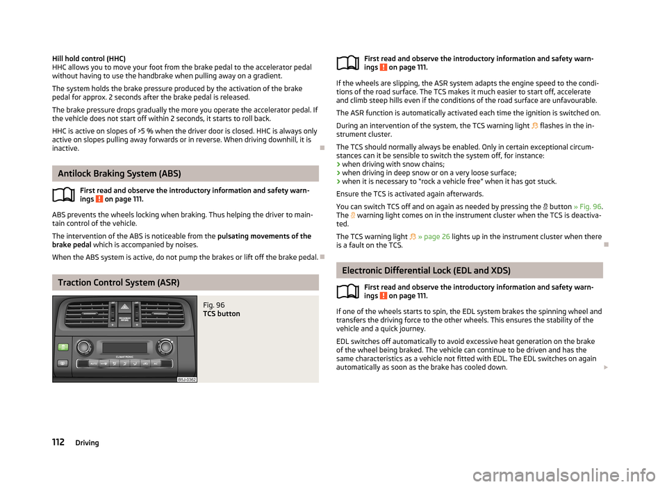
Fig. 96
TCS buttonFirst read and observe the introductory information and safety warn-
ings on page 111.
If the wheels are slipping, the ASR system adapts the engine speed to the condi-
tions of the road surface. The TCS makes it much easier to start off, accelerate
and climb steep hills even if the conditions of the road surface are unfavourable.
The ASR function is automatically activated each time the ignition is switched on.
During an intervention of the system, the TCS warning light flashes in the in-
strument cluster.
The TCS should normally always be enabled. Only in certain exceptional circum-
stances can it be sensible to switch the system off, for instance:
› when driving with snow chains;
› when driving in deep snow or on a very loose surface;
› when it is necessary to “rock a vehicle free” when it has got stuck.
Ensure the TCS is activated again afterwards.
You can switch TCS off and on again as needed by pressing the
button » Fig. 96 .
The
warning light comes on in the instrument cluster when the TCS is deactiva-
ted.
The TCS warning light
» page 26 lights up in the instrument cluster when there
is a fault on the TCS.
Electronic Differential Lock (EDL and XDS)
First read and observe the introductory information and safety warn-
ings
on page 111.
If one of the wheels starts to spin, the EDL system brakes the spinning wheel and
transfers the driving force to the other wheels. This ensures the stability of the
vehicle and a quick journey.
EDL switches off automatically to avoid excessive heat generation on the brake of the wheel being braked. The vehicle can continue to be driven and has the
same characteristics as a vehicle not fitted with EDL. The EDL switches on again
automatically as soon as the brake has cooled down.
112Driving
Page 116 of 223
XDL function (Fabia RS and Fabia Estate RS only)
XDL is an extension to the electronic differential lock. XDL does not respond to
traction, but to the relief of the inner front wheel during fast cornering. The active
brake intervention on the brake of the inner wheel prevents it from spinning.
Thus, the traction is improved and the vehicle continues to follow the desired
track.
Parking aid
Introduction
This chapter contains information on the following subjects:
Function
113
Activation/deactivation
114WARNING■ The parking aid is not a substitute for the driver paying proper attention and
it is always the driver's responsibility to take care when reversing the vehicle
or carrying out similar manoeuvres. Pay particular attention to small children
and animals as they are not recognised by the parking aid sensors.■
Before reversing, you should make sure that there are no small obstacles,
such as rocks, thin posts, trailer drawbars etc. behind your vehicle. Such ob-
stacles may not be recognised by the parking aid sensors.
■
Under certain circumstances, surfaces of certain objects and types of cloth-
ing cannot reflect the system signals. Thus, these objects or people who wear
such clothing are not recognised by the System sensors.
■
External sound sources can have a detrimental effect on the system. Under
adverse conditions, this may cause objects or people to not be recognised by the system.
CAUTION
■ If a warning signal sounds for about 3 seconds after activating the system and
there is no obstacle close to your car, this indicates a system fault. Have the fault
rectified by a specialist garage.■
The sensors must be kept clean (free of ice, etc.) to enable the parking aid to
operate properly.
■ Under adverse weather conditions (heavy rain, water vapour, very low or high
temperatures etc.) system function may be limited.■
Additionally fitted modules, such as a bicycle rack, can impair the function of the
parking aid.
Function
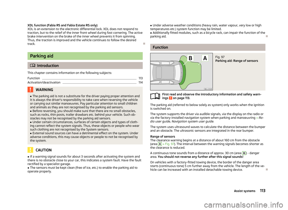
Fig. 97
Parking aid: Range of sensors
First read and observe the introductory information and safety warn- ings on page 113.
The parking aid (referred to below solely as system) only works when the ignition
is switched on.
The system supports the driver via audible signals, via the display on the radio or
via the factory-installed navigation system when parking and manoeuvring » Ra-
dio user guide, Navigation system user guide.
The system uses ultrasound waves to calculate the distance between the bumper
and an obstacle. The ultrasonic sensors are integrated in the rear bumper.
Range of sensors
The clearance warning begins at a distance of about 160 cm from the obstacle
(area
A
» Fig. 97 ). The interval between the warning signals becomes shorter as
the clearance is reduced.
A continuous tone sounds from a distance of approx. 30 cm (area
B
) - danger
area. You should not reverse any further after this signal sounds!
On vehicles with a factory-fitted towing device, the border of the danger area starts (continuous tone) 5 cm further away from the vehicle. The length of the ve-
hicle can be increased with an installed detachable towing device.
113Assist systems
Page 122 of 223
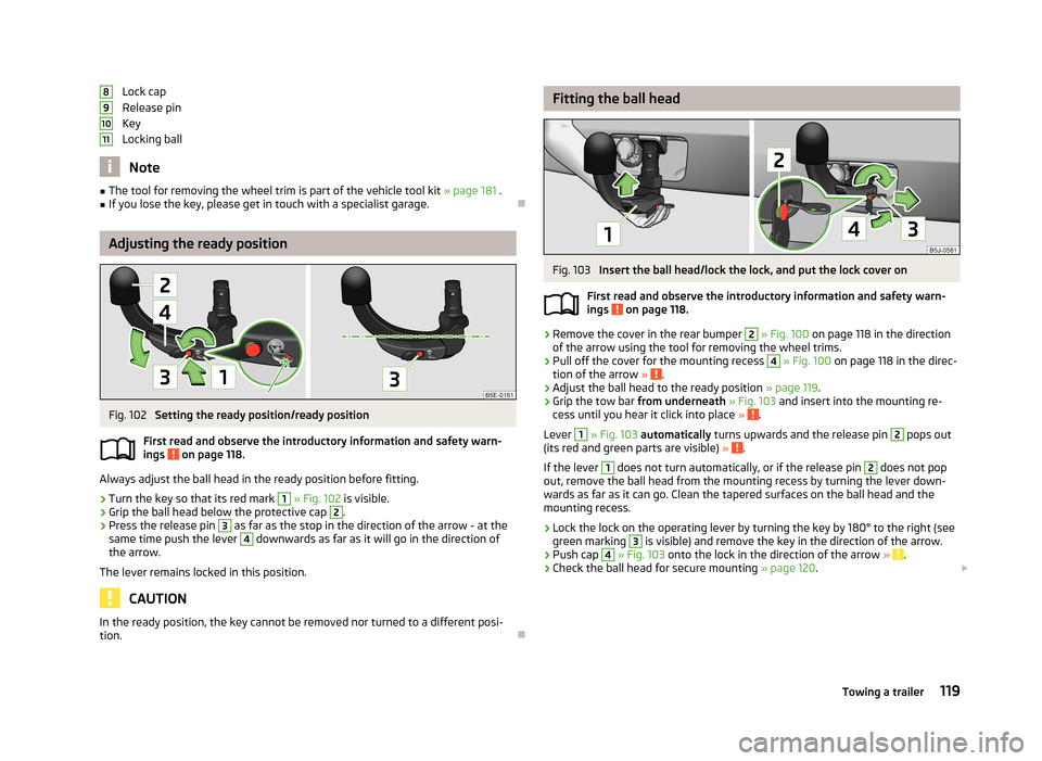
Lock cap
Release pin
Key
Locking ball
Note
■ The tool for removing the wheel trim is part of the vehicle tool kit » page 181 .■If you lose the key, please get in touch with a specialist garage.
Adjusting the ready position
Fig. 102
Setting the ready position/ready position
First read and observe the introductory information and safety warn- ings
on page 118.
Always adjust the ball head in the ready position before fitting.
›
Turn the key so that its red mark
1
» Fig. 102 is visible.
›
Grip the ball head below the protective cap
2
.
›
Press the release pin
3
as far as the stop in the direction of the arrow - at the
same time push the lever
4
downwards as far as it will go in the direction of
the arrow.
The lever remains locked in this position.
CAUTION
In the ready position, the key cannot be removed nor turned to a different posi-
tion.891011
Fitting the ball headFig. 103
Insert the ball head/lock the lock, and put the lock cover on
First read and observe the introductory information and safety warn-
ings
on page 118.
›
Remove the cover in the rear bumper
2
» Fig. 100 on page 118 in the direction
of the arrow using the tool for removing the wheel trims.
›
Pull off the cover for the mounting recess
4
» Fig. 100 on page 118 in the direc-
tion of the arrow » .
›
Adjust the ball head to the ready position » page 119.
›
Grip the tow bar from underneath » Fig. 103 and insert into the mounting re-
cess until you hear it click into place » .
Lever
1
» Fig. 103 automatically turns upwards and the release pin
2
pops out
(its red and green parts are visible) » .
If the lever
1
does not turn automatically, or if the release pin
2
does not pop
out, remove the ball head from the mounting recess by turning the lever down-
wards as far as it can go. Clean the tapered surfaces on the ball head and the
mounting recess.
›
Lock the lock on the operating lever by turning the key by 180° to the right (see
green marking
3
is visible) and remove the key in the direction of the arrow.
›
Push cap
4
» Fig. 103 onto the lock in the direction of the arrow » .
›
Check the ball head for secure mounting » page 120.
119Towing a trailer
Page 123 of 223
WARNING■Carefully remove the cap for the mounting recess - there is a risk of hand
injury.■
Keep your hands outside the lever's range of motion when attaching the ball
head – there is a risk of finger injury.
■
Never attempt to pull the operating lever upwards forcibly to turn the key.
Doing so would mean the ball head is not attached correctly.
CAUTION
■ After removing the key, always replace the cap on the lock of the operating lev-
er – there is a risk of dirt getting into the lock.■
Keep the mounting recess of the towing equipment clean at all times. Such dirt
prevents the ball head from being attached securely.
■
After removing the ball head, always place the cap on the mounting recess.
■
Remove the cover from the rear bumper with care - there is a risk of paint dam-
age to the bumper and the cap.
Note
Store cover 2 and cover 4 » Fig. 100 on page 118 in a suitable place in the lug-
gage compartment after removing them.
Check proper fitting
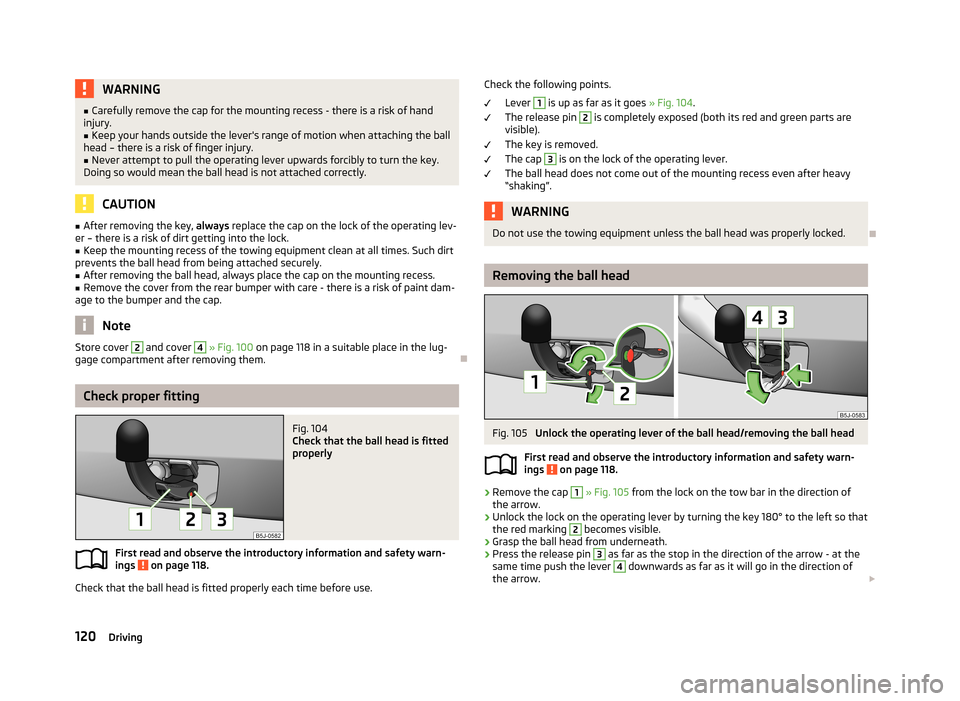
Fig. 104
Check that the ball head is fitted
properly
First read and observe the introductory information and safety warn-
ings on page 118.
Check that the ball head is fitted properly each time before use.
Check the following points.
Lever 1
is up as far as it goes » Fig. 104.
The release pin
2
is completely exposed (both its red and green parts are
visible).
The key is removed.
The cap
3
is on the lock of the operating lever.
The ball head does not come out of the mounting recess even after heavy
“shaking”.
WARNINGDo not use the towing equipment unless the ball head was properly locked.
Removing the ball head
Fig. 105
Unlock the operating lever of the ball head/removing the ball head
First read and observe the introductory information and safety warn- ings
on page 118.
›
Remove the cap
1
» Fig. 105 from the lock on the tow bar in the direction of
the arrow.
›
Unlock the lock on the operating lever by turning the key 180° to the left so that
the red marking
2
becomes visible.
›
Grasp the ball head from underneath.
›
Press the release pin
3
as far as the stop in the direction of the arrow - at the
same time push the lever
4
downwards as far as it will go in the direction of
the arrow.
120Driving
Page 125 of 223
The distribution of the weight is very poor if your vehicle is unladen and the trail-
er is laden. Maintain a particularly low speed if you cannot avoid driving with this
combination.
Tyre pressure
Correct the tyre inflation pressure on your vehicle for a “full load” » page 174,
Tyre service life .
Trailer load
The permissible trailer load must not be exceeded under any circumstan- ces » page 201 , Technical data .
The trailer loads specified apply only to altitudes up to 1 000 metres above mean
sea level.
The engine output falls as altitude increases, as does the ability to climb. There-
fore, for every additional 1000 m in height (or part), the maximum permissible
towed weight must be reduced by 10 %.
The towed weight comprises the actual weights of the (loaded) towing vehicleand the (loaded) trailer.
The trailer and drawbar load information on the type plate of the towing equip- ment are merely test data for the towing equipment. The vehicle-specific values
are detailed in the vehicle documents.WARNING■ Do not exceed the maximum permissible axle and drawbar load and the
maximum permissible total or towed weight of the vehicle and the trailer –
there is the risk of an accident and serious injury.■
Slipping loads can significantly affect the stability and safety of the vehicle/
trailer combination – there is the risk of an accident and serious injury.
Towing a trailer
First read and observe the introductory information and safety warn-
ings
on page 121.
Exterior mirrors
You have to have additional exterior mirrors fitted if you are not able to see the
traffic behind the trailer with the standard rear-view mirrors. National legal re-
quirements must be observed.
Headlights
The front of the vehicle can be lifted when a trailer is being towed and the head-
lights can dazzle other road users.
Adjust the headlight setting on the headlight range control » page 44, Headlight
beam adjustment .
Driving speed
For safety reasons, do not drive faster than 80 km/h when towing a trailer.
Immediately reduce your speed as soon as even the slightest swaying of the trail- er is detected. Never attempt to stop the trailer from “swaying” by accelerating.
Brakes
Apply the brakes in good time! If the trailer is fitted with a trailer brake, apply the
brakes gently at first, then brake firmly. This will avoid brake jolts resulting from
the trailer wheels locking.
On downhill sections shift down a gear in good time to also use the engine as a
brake.
Engine overheating
The speed must be reduced immediately if the needle for the coolant tempera- ture gauge moves into the right-hand area or the red area of the scale.
Stop and switch off the engine if the warning light
in the instrument cluster
starts to flash. Wait a few minutes and check the level of coolant » page 167,
Checking the coolant level .
The following guidelines must be observed » page 22,
Coolant .
The coolant temperature can be reduced by switching on the heating.WARNING■ Adapt your speed to the conditions of the road surface and to the traffic sit-
uation.■
Improper or incorrectly connected electric cables can energise the trailer and
cause functional faults to the vehicle's entire electrical system as well as acci-
dents and severe injuries.
■
Work on the electrical system must only be carried out by specialist garages.
■
Never directly connect the trailer's electrical system with the electrical con-
nections for the tail lights or other current sources.
122Driving