lock SKODA FABIA 2013 2.G / 5J Repair Manual
[x] Cancel search | Manufacturer: SKODA, Model Year: 2013, Model line: FABIA, Model: SKODA FABIA 2013 2.G / 5JPages: 223, PDF Size: 12.77 MB
Page 159 of 223
We recommend that you remove dust at regular short intervals with a cloth or
vacuum cleaner.
Clean soiled leather surfaces with a cotton or woollen cloth lightly moistened
with water and then dry with a clean dry cloth »
.
Clean more severely soiled areas with a cloth soaked in a mild soap solution (2
tablespoons of natural soap to 1 litre of water).
Use a cleaning agent specially developed for the purpose to remove stains.
Treat the leather with a suitable leather care product at suitable regular intervals.
CAUTION
■ Ensure that the leather is not soaked through at any point during cleaning and
that no water gets into the stitching of the seams. The leather would then be-
come brittle and cracked.■
Avoid leaving the vehicle for lengthy periods in bright sunlight to avoid the
leather from bleaching. If the vehicle is parked in the open for lengthy periods,
protect the leather from direct sunlight by covering it.
■
Sharp-edged objects on items of clothing such as zip fasteners, rivets, sharp-
edged belts, jewellery and pendants may leave permanent scratches or signs of
rubbing on the surface. Damage of this nature cannot later be recognized as a
justified complaint.
■
The use of a mechanical steering wheel lock may damage the leather surface of
the steering wheel.
■
Use a care cream with light blocker and impregnation effect on a regular basis
and each time after cleaning. The cream nourishes the leather, allows it to
breathe and keeps it supple and also provides moisture. It also creates surface
protection.
■
Some clothing materials, such as dark denim, do not have sufficient colour fast-
ness. This can cause damage or clearly visible discolouration to seat covers even
when treated correctly. This is particularly true for light-coloured upholstery. This
is not a defect in the seat cover, but poor colour fastness of the clothing textiles.
Note
During the life of the vehicle, minor visible changes can occur on the leather parts
of the covers (e. g wrinkles or creases as a result of the stress of the covers).
Synthetic leather, fabrics and Alcantara ®
First read and observe the introductory information and safety warn- ings
on page 155.
Synthetic leather
Clean the synthetic leather with a damp cloth.
If the synthetic leather does not come completely clean with this method, a mild soap solution or specific cleaning agent must be used.
Fabrics
Clean upholstery cover materials and cloth trims on doors, boot cover, etc. using
specific cleaning agents, e.g., dry foam.
Use a soft sponge, brush, or commercially available microfibre cloth. Use a cloth and special detergent to clean the headlining.
Remove pilling and residues on upholstery with a brush.Remove stubborn hair with a “cleaning glove”.
Alcantara ®
Dust and fine dirt particles in pores, creases and seams may chafe and damage
the surface.
If you leave your vehicle parked in the open for lengthy periods, protect the Al-
cantara ®
seat upholstery from direct sunlight to prevent fading.
Minor changes in colour caused by use are normal.
CAUTION
■ Do not use leather cleaners on Alcantara ®
seat upholstery.■Do not use solvents, floor wax, shoe cream, stain remover or similar agents on
Alcantara ®
seat upholstery.■
Avoid leaving the vehicle for lengthy periods in bright sunlight to prevent the
fabrics from bleaching. If the vehicle is parked in the open for lengthy periods,
protect the fabrics against direct sunlight by covering them.
■
Some clothing materials, such as dark denim, do not have sufficient colour fast-
ness. This can cause damage or clearly visible discolouration to seat covers even when treated correctly. This is particularly true for light-coloured upholstery. This
is not a defect in the seat cover, but poor colour fastness of the clothing textiles.
156General Maintenance
Page 161 of 223
Inspecting and replenishing
Fuel
Introduction
This chapter contains information on the following subjects:
Refuelling
158
Unleaded petrol
159
Diesel fuel
160
The correct grades of fuel for your vehicle are stated on a sticker affixed to the
inside of the fuel filler flap » Fig. 122 on page 158 -
.
WARNINGThe national legal requirements must be observed if carrying a spare canister
in the vehicle. We do not recommend carrying any fuel canisters in your vehi-
cle for safety reasons. In the event of an accident this could be damaged and
fuel could escape – there is a risk of fire.
CAUTION
■ Never drive until the fuel tank is completely empty! The irregular supply of fuel
can cause misfiring, which can result in considerable damage to parts of the en-
gine and exhaust system.■
Immediately remove any fuel that has spilled onto the vehicle's paintwork –
there is a risk of paint damage.
■
If the vehicle was not purchased in the country in which it was intended to be
operated, you should check whether the fuel specified by the manufacturer is of-
fered in the country where the vehicle will be operated. You should also perhaps
check whether the manufacturer has recommended a different fuel for operation
of the vehicle in the country concerned. Is this not the case, then you must check
whether the manufacturer permits operation of the vehicle with another fuel
type.
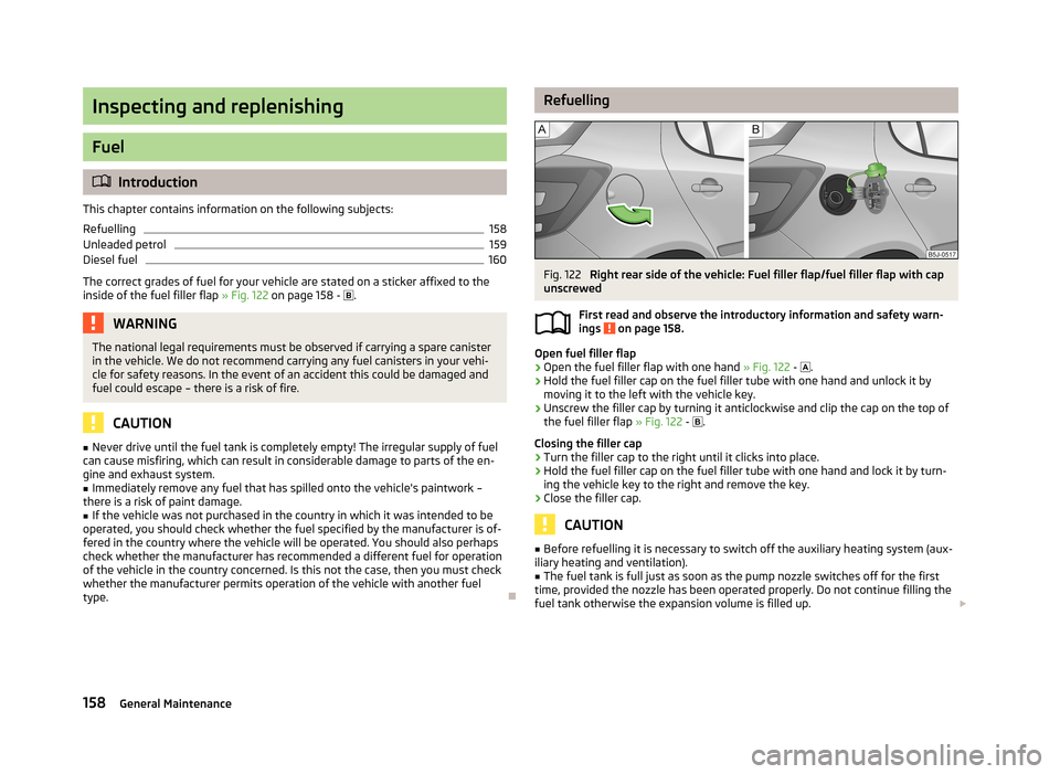
RefuellingFig. 122
Right rear side of the vehicle: Fuel filler flap/fuel filler flap with cap
unscrewed
First read and observe the introductory information and safety warn-
ings
on page 158.
Open fuel filler flap
›
Open the fuel filler flap with one hand » Fig. 122 -
.
›
Hold the fuel filler cap on the fuel filler tube with one hand and unlock it by
moving it to the left with the vehicle key.
›
Unscrew the filler cap by turning it anticlockwise and clip the cap on the top ofthe fuel filler flap » Fig. 122 -
.
Closing the filler cap
›
Turn the filler cap to the right until it clicks into place.
›
Hold the fuel filler cap on the fuel filler tube with one hand and lock it by turn- ing the vehicle key to the right and remove the key.
›
Close the filler cap.
CAUTION
■ Before refuelling it is necessary to switch off the auxiliary heating system (aux-
iliary heating and ventilation).■
The fuel tank is full just as soon as the pump nozzle switches off for the first
time, provided the nozzle has been operated properly. Do not continue filling the fuel tank otherwise the expansion volume is filled up. 158General Maintenance
Page 164 of 223
WARNINGPlease read the following advice before beginning work in the engine com-
partment.■
Turn off the engine and withdraw the ignition key.
■
Firmly apply the handbrake.
■
If the vehicle is fitted with a manual gearbox, move the gearshift lever into
Neutral, or if the vehicle is fitted with an automatic gearbox, move the selec-
tor lever into position P.
■
Allow the engine to cool.
■
Never open the bonnet if you can see steam or coolant flowing out of the
engine compartment – there is a risk of scalding. Wait until the steam or cool- ant has stopped escaping.
WARNINGPlease read the following advice for work in the engine compartment.■Keep children clear of the engine compartment.■
Never touch the radiator fan while the engine is still warm. The fan might
suddenly start running!
■
Do not touch any hot engine parts – there is a risk of burns.
■
The coolant additive and thus all of the coolant is harmful to your health.
■
Avoid contact with the coolant.
■
Coolant vapours are harmful to health.
■
Never open the end cover of the coolant expansion reservoir while the en-
gine is still warm. The cooling system is pressurized!
■
When opening the end cover of the coolant expansion reservoir, cover it
with a cloth to protect your face, hands and arms from hot steam or hot cool-
ant.
■
If any coolant splashes into your eyes, immediately rinse out your eyes with
clear water and contact a doctor as soon as possible.
■
Always safely store the coolant additive in its original container out of the
reach of children – there is a risk of poisoning.
■
Consult a doctor immediately if coolant is swallowed.
■
Do not leave any items (e.g. cleaning cloths or tools) in the engine compart-
ment.
■
Never spill fluids on the hot engine. Such fluids (e.g. the antifreeze con-
tained in the coolant) may ignite!
WARNINGThe following warning instructions must be observed at all times when work-
ing in the engine compartment while the engine is running.■
Pay particular attention to moving engine parts (e.g. V-ribbed belt, alterna-
tor, radiator fan) and the high-voltage ignition unit – there is a risk of death.
■
Never touch the electric wiring on the ignition system.
■
Avoid short circuits in the electrical system - particularly on the vehicle's
battery.
■
Always make sure that no jewellery, loose clothing or long hair can get
caught in rotating engine parts – there is a risk of death. Always remove any jewellery, tie back long hair and wear tight fitting clothing before completing
any work.
WARNINGThe following warning instructions must be observed if work has to be carried
out on the fuel or electrical systems.■
Always disconnect the vehicle battery from the electrical system.
■
Do not smoke.
■
Never work near open flames.
■
Always have a functioning fire extinguisher nearby.
WARNING■ Read the information and warning instructions on the fluid containers.■Keep fluids in their original containers and keep out of reach of children!■
If you wish to work under the vehicle, you must secure the vehicle against
rolling away and support it with suitable axle stands: the car jack is not suffi-
cient for this – there is a risk of injury.
■
Never cover the engine with additional insulation material (e.g. with a blan-
ket) – there is a risk of fire.
■
The bonnet must always be properly closed when driving. This is why after
closing the bonnet, the lock must always be checked to ensure it has engaged properly.
■
If you notice that the lock is not properly engaged while driving, stop the ve-
hicle immediately and close the bonnet – there is the risk of an accident.
161Inspecting and replenishing
Page 165 of 223
CAUTIONAlways top up using the correct specification of fluids. This may result in major
operating problems and also vehicle damage!
For the sake of the environment
In view of the requirements for the environmentally friendly disposal of fluids and the special tools and knowledge required for such work, we recommend that flu-
ids be changed by a specialist garage.
Note
■ If there is anything you are not sure about concerning fluids, please consult a
specialist garage.■
Fluids with the correct specifications can be purchased from ŠKODA Original Ac-
cessories.
Opening and closing the bonnet
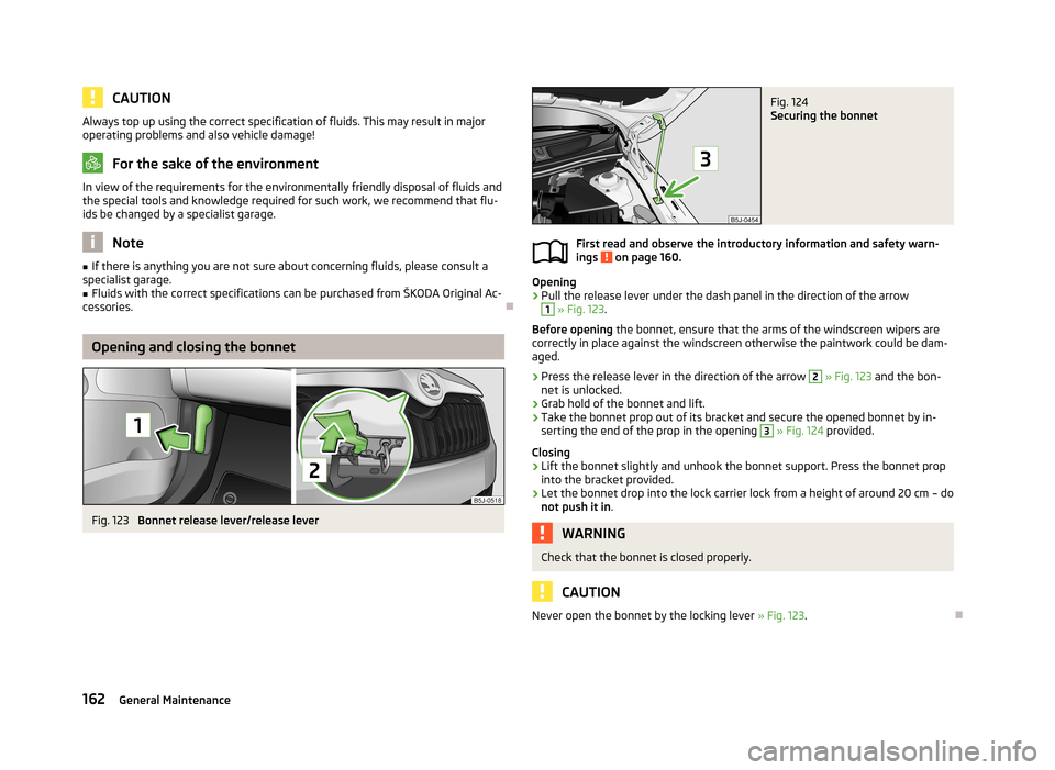
Fig. 123
Bonnet release lever/release lever
Fig. 124
Securing the bonnet
First read and observe the introductory information and safety warn-
ings on page 160.
Opening
›
Pull the release lever under the dash panel in the direction of the arrow
1
» Fig. 123 .
Before opening the bonnet, ensure that the arms of the windscreen wipers are
correctly in place against the windscreen otherwise the paintwork could be dam- aged.
›
Press the release lever in the direction of the arrow
2
» Fig. 123 and the bon-
net is unlocked.
›
Grab hold of the bonnet and lift.
›
Take the bonnet prop out of its bracket and secure the opened bonnet by in- serting the end of the prop in the opening
3
» Fig. 124 provided.
Closing
›
Lift the bonnet slightly and unhook the bonnet support. Press the bonnet prop into the bracket provided.
›
Let the bonnet drop into the lock carrier lock from a height of around 20 cm – do
not push it in .
WARNINGCheck that the bonnet is closed properly.
CAUTION
Never open the bonnet by the locking lever » Fig. 123
.
162General Maintenance
Page 175 of 223
WARNING“Quick-charging” the vehicle battery is dangerous and requires a special
charger and specialist knowledge.
CAUTION
On vehicles with the START/STOP system, the pole terminal of the charger must
not be connected directly to the negative terminal of the vehicle battery, but only
to the engine earth » page 189, Jump-starting in vehicles with the START-STOP
system .
Note
We therefore recommend that vehicle batteries be rapid charged by a specialist
garage.
Disconnecting or reconnecting
First read and observe the introductory information and safety warn-ings
on page 169.
The following functions are initially deactivated or are no longer able to operate
faultlessly after the vehicle battery has been disconnected and reconnected.
OperationOperating measureElectrical power window (operational faults)» page 40Enter the radio/navigation system code num-
ber» User manual of the radio
or » user manual of the naviga-
tion systemSetting the clock» page 12Data in the multifunction display are deleted.» page 13
Note
We recommend having the vehicle checked by a specialist garage to ensure the
full functionality of all electrical systems.
Replacing
First read and observe the introductory information and safety warn-
ings
on page 169.
When replacing a battery, the new vehicle battery must have the same capacity,
voltage, amperage and be the same size. Suitable vehicle batteries can be pur-
chased from a specialist dealer.
We recommend that the battery is replaced by a specialist garage, where the new
vehicle battery will be installed properly and the original battery will be disposed
of in accordance with national regulations.
Automatic load deactivation
First read and observe the introductory information and safety warn-ings
on page 169.
The vehicle voltage control unit automatically prevents the battery from discharg-
ing when the battery is subjected to heavy loads. This may be noticed from the following.
› The idling speed is raised to allow the generator to deliver more electricity to
the electrical system.
› Where appropriate large convenience consumers, e.g. seat heaters, rear win-
dow heaters, have their power limited or shut off completely if necessary.
CAUTION
■ Despite such intervention by the vehicle electric system management, the vehi-
cle battery may be drained. For example, when the ignition is switched on a long
time with the engine turned off or the side or parking lights are turned on during longer parking.■
Consumers which are supplied via a 12 V socket can cause the vehicle battery to
discharge when the ignition is switched off.
Note
Driving comfort is not disrupted by any shutting off of consumers. Often the driv-
er is not aware of it having taken place.
172General Maintenance
Page 180 of 223
WARNING■When the warning light illuminates, immediately reduce the speed and
avoid sudden steering and brake manoeuvres. Stop the vehicle as soon as
possible and inspect the tyres and their inflation pressure.■
Under certain circumstances (e.g. sporty style of driving, wintry or unpaved
roads) the warning light can be delayed or does not light up at all.
CAUTION
■
The tyre control display does therefore not replace the regular tyre inflation
pressure control, as the system cannot detect an even loss of pressure.■
The system cannot warn in case of very rapid loss of tyre pressure, e.g. in the
event of a sudden puncture. In this case carefully bring the vehicle to a standstill without sudden steering movements or sharp braking.
■
The basic setting must be repeated every 10,000 km or once a year to ensure
proper functioning of the tyre pressure monitor.
Spare wheel
Fig. 135
Boot: Spare wheel
First read and observe the introductory information and safety warn-
ings on page 173.
The spare wheel is located in a well under the floor covering in the luggage com-
partment and held by a special nut » Fig. 135.
Taking the wheel out
›
Open the tailgate.
›
Lift up the floor in the luggage compartment.
›
Remove the box with the tool kit.
›
Unscrew the nut » Fig. 135 anticlockwise.
›Take out the wheel.
Stowing the wheel›
Stow the replaced wheel in the spare wheel well with the rim facing down.
›
Screw on the nut » Fig. 135 clockwise until the wheel is safely secured.
›
Replace the box with the tool kit into the spare wheel and secure it with the
tape.
›
Fold back the floor in the luggage compartment.
›
Close the tailgate.
Install a wheel of the appropriate version and dimensions as soon as possible.
If the dimensions or design of the spare wheel differ from the tyres fitted to the
vehicle (e.g. winter tyres or low-profile tyres), it must only be used briefly in the
event of a puncture and if an appropriately cautious style of driving is adop-
ted »
.
Temporary spare wheel
A yellow warning label is displayed on the rim of the temporary spare wheel.
Please note the following if you intend to use the temporary spare wheel. › The warning label must not be covered after installing the wheel.
› Be specially attentive when driving.
› The pressure for the temporary spare wheel is identical to the maximum pres-
sure of the standard tyres.
› Only use this temporary spare wheel to reach the nearest specialist garage
since it is not intended for permanent use.
WARNING■ Never use the temporary spare wheel if it is damaged.■If the dimensions or design of the temporary spare wheel differ from the fit-
ted tyres, never drive faster than 80 km/h (or 50 mph).■
Avoid accelerating at full throttle, sharp braking and fast cornering.
CAUTION
Observe the instructions on the warning sign of the temporary spare wheel.
177Wheels
Page 182 of 223
Wheel boltsFirst read and observe the introductory information and safety warn-ings
on page 173.
Wheels and wheel bolts are matched to each other in terms of design. Whenever
you change the wheels fitted, e.g. light alloy wheels or wheels with winter tyres,
you must also use the matching wheel bolts of the correct length and shape of
bolt head. Correct fastening of the wheels depends on this.
Winter use
Introduction
This chapter contains information on the following subjects:
Winter tyres
179
Snow chains
179
Winter tyres
First read and observe the introductory information given on page 179.
The handling of your vehicle will be significantly improved when driving on wintry
roads if you fit winter tyres. Summer tyres have less grip on ice, snow and at tem- peratures below 7 °C. This is especially true of low-profile tyres or high-speed
tyres .
To achieve the best possible handling properties, winter tyres must be fitted on
all four wheels, the minimum tread depth must be 4 mm and tyres must be no
older than 4 years.
Winter tyres of a lower speed category can be used provided that the permissible
maximum speed of these tyres is not exceeded even if the possible maximum
speed of the vehicle is higher.
The speed limit for winter tyres can be set in the MAXI DOT display in the Winter
tyres menu item » page 18.
For the sake of the environmentRe-fit the summer tyres at an appropriate time as they provide better handling
properties, a shorter braking distance, less tyre noise, and reduced tyre wear on
roads which are free of snow and ice as well as at temperatures above 7 °C. The
fuel consumption is also lower.
Snow chains
First read and observe the introductory information given on page 179.
When driving on wintry roads, snow chains improve not only traction, but also the
braking performance.
Snow chains must only be mounted on the front wheels.
For technical reasons, it is only permissible to fit snow chains with the following wheel/tyre combinations.
Wheel sizeDepth (D)Tyre size5J x 1435 mm165/706J x 1437 mm185/606J x 1543 mm185/55
Only fit snow chains with links and locks not larger than 12 mm.
CAUTION
■
The chains must be removed when driving on roads which are free of snow.
They adversely affect the handling of your vehicle, damage the tyres and are rap-
idly destroyed.■
Remove the full wheel trims before installing the snow chains.
179Wheels
Page 185 of 223
WARNINGObserve the following instructions for raising the vehicle.■If the wheel has to be changed on a slope, first of all block the opposite
wheel with a stone or similar object to prevent the vehicle from unexpectedly
rolling away.■
Secure the base plate of the lifting jack with suitable means to prevent pos-
sible moving. A soft and slippery ground under the base plate may move the
lifting jack, causing the vehicle to fall down. It is therefore always necessary to
place the lifting jack on a solid surface or use a wide and stable base. Use a
non-slip base (e.g. a rubber foot mat) if the surface is smooth, such as cobbled
stones, tiled floor, etc.
■
Only attach the lifting jack to the attachment points provided for this pur-
pose.
■
Always raise the vehicle with the doors closed.
■
Never position any body parts, such as arms or legs under the vehicle, while
the vehicle is raised with a lifting jack.
■
Never start the engine with the vehicle sitting on the raised jack – there is a
risk of injury.
CAUTION
■ The tightening torque specified for the wheel bolts for steel and light alloy
wheels is 120 Nm.■
If the wheel bolts are fastened too tightly, this can cause damage to the anti-
theft wheel bolt or the adapter.
Note
■ The anti-theft wheel bolt set and adapter can be purchased from a ŠKODA Part-
ner.■
The national legal requirements must be observed when changing a wheel.
Preparation
First read and observe the introductory information and safety warn-
ings
on page 181.
Always change a wheel on a level surface as far as possible.
The following steps must be carried out before actually changing the wheel:
› Have
all the occupants get out. The passengers should not stand on the road
(instead they should remain behind a crash barrier, for instance) while the wheel is being changed.›
Switch off the engine.
›
Move the gearshift lever into Neutral or move the selector lever for the auto-
matic gearbox into position P.
›
Apply the handbrake firmly.
›
Uncouple any trailer.
›
Remove the vehicle tool kit » page 181 and the spare wheel » page 177 , Spare
wheel from the boot.
Changing a wheel
First read and observe the introductory information and safety warn-
ings
on page 181.
›
Remove the full wheel trim » page 178 or caps » page 178 .
›
In the case of light alloy wheel rims remove the wheel trim cap » page 178.
›
First of all slacken the anti-theft wheel bolt and then the other wheel
bolts » page 183 .
›
Jack up the vehicle until the wheel that needs changing is clear of the
ground » page 184 .
›
Unscrew the wheel bolts and place them on a clean surface (cloth, paper, etc.).
›
Remove the wheel carefully.
›
Attach the spare wheel and slightly screw on the wheel bolts.
›
Lower the vehicle.
›
Tighten the opposite wheel bolts alternately (cross-wise) with the wheel
wrench. Tighten the anti-theft wheel bolt last » page 183.
›
Reinstall the wheel trim/wheel trim cap or the caps.
Note
■
All bolts must be clean and must turn easily.■Under no circumstances grease or oil the wheel bolts!■
When fitting unidirectional tyres, ensure that the direction of rotation is cor-
rect » page 176 , Unidirectional tyres .
182Do-it-yourself
Page 189 of 223
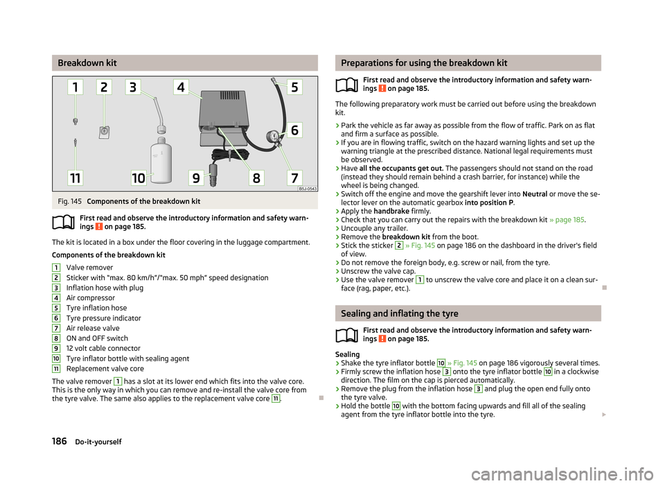
Breakdown kitFig. 145
Components of the breakdown kit
First read and observe the introductory information and safety warn-
ings
on page 185.
The kit is located in a box under the floor covering in the luggage compartment.
Components of the breakdown kit Valve remover
Sticker with “max. 80 km/h”/“max. 50 mph” speed designation
Inflation hose with plug
Air compressor
Tyre inflation hose
Tyre pressure indicator
Air release valve
ON and OFF switch
12 volt cable connector
Tyre inflator bottle with sealing agent
Replacement valve core
The valve remover
1
has a slot at its lower end which fits into the valve core.
This is the only way in which you can remove and re-install the valve core from
the tyre valve. The same also applies to the replacement valve core
11
.
1234567891011Preparations for using the breakdown kit
First read and observe the introductory information and safety warn-
ings
on page 185.
The following preparatory work must be carried out before using the breakdown
kit.
›
Park the vehicle as far away as possible from the flow of traffic. Park on as flat and firm a surface as possible.
›
If you are in flowing traffic, switch on the hazard warning lights and set up thewarning triangle at the prescribed distance. National legal requirements must
be observed.
›
Have all the occupants get out. The passengers should not stand on the road
(instead they should remain behind a crash barrier, for instance) while the wheel is being changed.
›
Switch off the engine and move the gearshift lever into Neutral or move the se-
lector lever on the automatic gearbox into position P.
›
Apply the handbrake firmly.
›
Check that you can carry out the repairs with the breakdown kit » page 185.
›
Uncouple any trailer.
›
Remove the breakdown kit from the boot.
›
Stick the sticker
2
» Fig. 145 on page 186 on the dashboard in the driver's field
of view.
›
Do not remove the foreign body, e.g. screw or nail, from the tyre.
›
Unscrew the valve cap.
›
Use the valve remover
1
to unscrew the valve core and place it on a clean sur-
face (rag, paper, etc.).
Sealing and inflating the tyre
First read and observe the introductory information and safety warn-
ings
on page 185.
Sealing
›
Shake the tyre inflator bottle
10
» Fig. 145 on page 186 vigorously several times.
›
Firmly screw the inflation hose
3
onto the tyre inflator bottle
10
in a clockwise
direction. The film on the cap is pierced automatically.
›
Remove the plug from the inflation hose
3
and plug the open end fully onto
the tyre valve.
›
Hold the bottle
10
with the bottom facing upwards and fill all of the sealing
agent from the tyre inflator bottle into the tyre.
186Do-it-yourself
Page 191 of 223
WARNING (Continued)■The non-insulated parts of the terminal clamps must never touch each other
– there is a risk of short circuit.■
The jump-start cable connected to the positive terminal of the battery must
not come into contact with electrically conducting parts of the vehicle – there
is a risk of short circuit.
■
Do not clamp the jump-start cable to the negative terminal of the dis-
charged battery. There is the risk of detonating gas seeping out the battery
being ignited by the strong spark which results from the engine being started.
■
Route the jump-start cables so that they cannot be caught by any rotating
parts in the engine compartment.
■
Do not bend over the battery – there is a risk of caustic burns.
■
The vent screws of the battery cells must be tightened firmly.
■
Keep any sources of ignition (naked flame, lit cigarettes, etc.) away from the
battery – there is a risk of explosion.
■
Never jump-start vehicle batteries with an electrolyte level that is too low –
risk of explosion and caustic burns.
CAUTION
■ There must not be any contact between the two vehicles otherwise current
may flow as soon as the negative terminals are connected.■
The discharged battery must be properly connected to the system of the vehi-
cle.
■
We recommend you buy jump-start cables from a car battery specialist.
Jump-starting using the battery from another vehicle
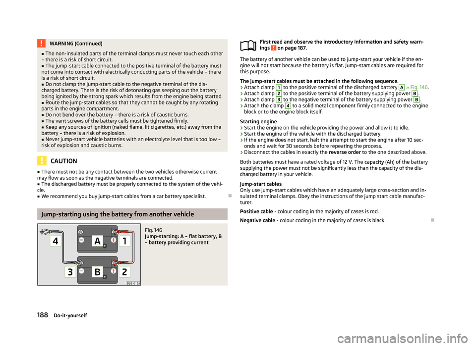
Fig. 146
Jump-starting: A – flat battery, B
– battery providing current
First read and observe the introductory information and safety warn-
ings on page 187.
The battery of another vehicle can be used to jump-start your vehicle if the en- gine will not start because the battery is flat. Jump-start cables are required for
this purpose.
The jump-start cables must be attached in the following sequence.
›
Attach clamp
1
to the positive terminal of the discharged battery
A
» Fig. 146 .
›
Attach clamp
2
to the positive terminal of the battery supplying power
B
.
›
Attach clamp
3
to the negative terminal of the battery supplying power
B
.
›
Attach the clamp
4
to a solid metal component firmly connected to the engine
block or to the engine block itself.
Starting engine
›
Start the engine on the vehicle providing the power and allow it to idle.
›
Start the engine of the vehicle with the discharged battery.
›
If the engine does not start, halt the attempt to start the engine after 10 sec- onds and wait for 30 seconds before repeating the process.
›
Disconnect the cables in exactly the reverse order to the one described above.
Both batteries must have a rated voltage of 12 V. The capacity (Ah) of the battery
supplying the power must not be significantly less than the capacity of the dis-
charged battery in your vehicle.
Jump-start cables
Only use jump-start cables which have an adequately large cross-section and in-
sulated terminal clamps. Obey the instructions of the jump start cable manufac-
turer.
Positive cable - colour coding in the majority of cases is red.
Negative cable - colour coding in the majority of cases is black.
188Do-it-yourself