air condition SKODA FABIA 2014 2.G / 5J User Guide
[x] Cancel search | Manufacturer: SKODA, Model Year: 2014, Model line: FABIA, Model: SKODA FABIA 2014 2.G / 5JPages: 197, PDF Size: 13.56 MB
Page 79 of 197
WARNING■The items being transported on the roof rack must be reliably attached –
there is the risk of an accident.■
Always secure the load with appropriate and undamaged lashing straps
or tensioning straps.
■
Distribute the load evenly over the roof rack system.
■
The handling properties of your vehicle change when you transport heavy
or bulky items on the roof rack system as a result of the centre of gravity
being shifted and the greater area exposed to the wind – there is the risk
of an accident. The style of driving and speed must therefore be adapted to
the current circumstances.
■
Avoid abrupt and sudden driving/braking manoeuvres.
■
Adjust the speed and driving style to the visibility, weather, road and traf-
fic conditions.
■
The permissible roof load, permissible axle loads and gross permissible
weight of the vehicle must not be exceeded under any circumstances –
there is the risk of an accident.
CAUTION
■ Only roof racks from the ŠKODA Original Accessories range should be used.■The fitting instructions supplied with the roof luggage rack system must be
observed when handling roof racks.■
On models fitted with a power sliding/tilting roof, ensure that the opened
sliding/tilting roof does not strike any items of luggage transported on the
roof.
■
Ensure that the boot lid does not hit the roof load when opened.
■
The height of the vehicle changes after mounting a roof luggage rack system
and the load that is secured to it. Compare the vehicle height with available
clearances, such as underpasses and garage doors.
■
Always remove the roof luggage rack system before entering an automated
car wash.
■
Ensure the roof aerial is not impaired by the secured load.
For the sake of the environment
The increased aerodynamic drag results in a higher fuel consumption.
Note
If the vehicle is not factory-equipped with a roof rack, it can be purchased from
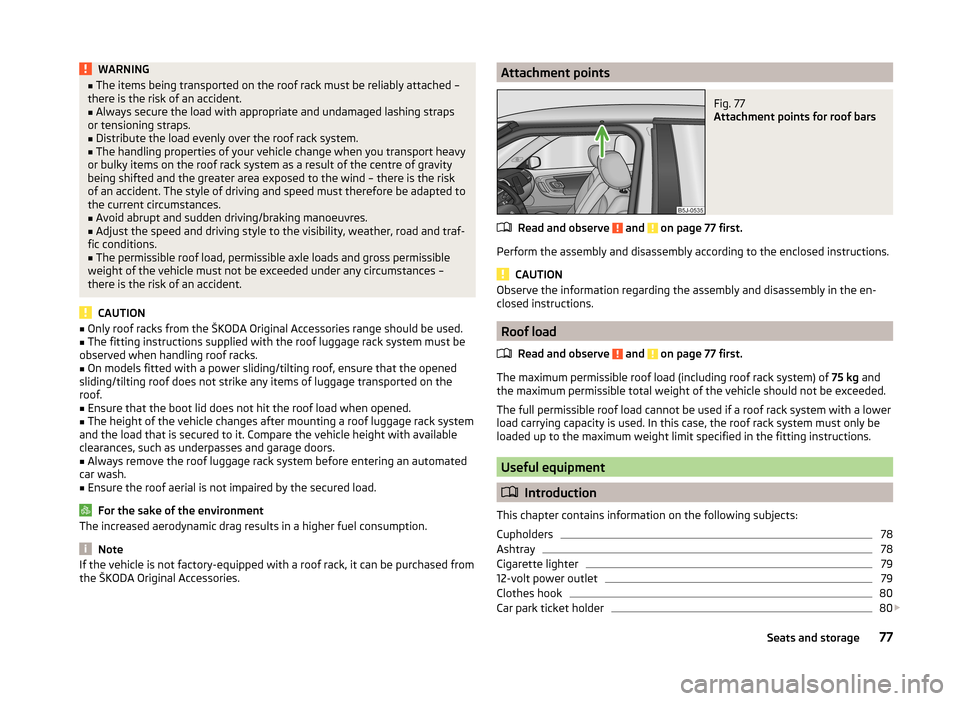
the ŠKODA Original Accessories.Attachment pointsFig. 77
Attachment points for roof bars
Read and observe and on page 77 first.
Perform the assembly and disassembly according to the enclosed instructions.
CAUTION
Observe the information regarding the assembly and disassembly in the en-
closed instructions.
Roof load
Read and observe
and on page 77 first.
The maximum permissible roof load (including roof rack system) of 75 kg and
the maximum permissible total weight of the vehicle should not be exceeded.
The full permissible roof load cannot be used if a roof rack system with a lower
load carrying capacity is used. In this case, the roof rack system must only be
loaded up to the maximum weight limit specified in the fitting instructions.
Useful equipment
Introduction
This chapter contains information on the following subjects:
Cupholders
78
Ashtray
78
Cigarette lighter
79
12-volt power outlet
79
Clothes hook
80
Car park ticket holder
80
77Seats and storage
Page 83 of 197
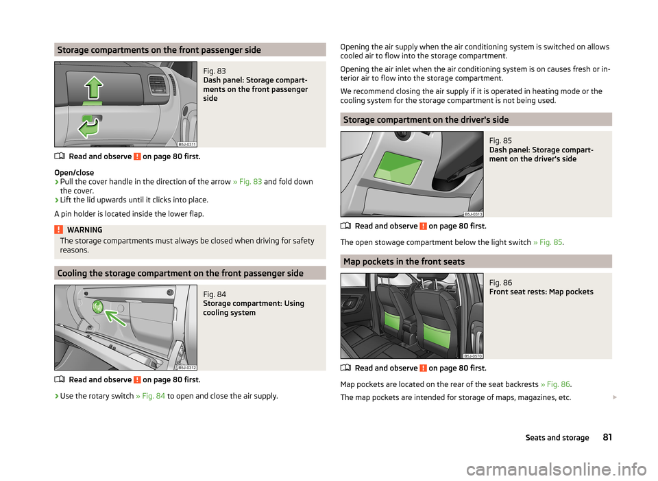
Storage compartments on the front passenger sideFig. 83
Dash panel: Storage compart-
ments on the front passenger
side
Read and observe on page 80 first.
Open/close
›
Pull the cover handle in the direction of the arrow » Fig. 83 and fold down
the cover.
›
Lift the lid upwards until it clicks into place.
A pin holder is located inside the lower flap.
WARNINGThe storage compartments must always be closed when driving for safety
reasons.
Cooling the storage compartment on the front passenger side
Fig. 84
Storage compartment: Using
cooling system
Read and observe on page 80 first.
›
Use the rotary switch » Fig. 84 to open and close the air supply.
Opening the air supply when the air conditioning system is switched on allows
cooled air to flow into the storage compartment.
Opening the air inlet when the air conditioning system is on causes fresh or in-
terior air to flow into the storage compartment.
We recommend closing the air supply if it is operated in heating mode or the
cooling system for the storage compartment is not being used.
Storage compartment on the driver's side
Fig. 85
Dash panel: Storage compart-
ment on the driver's side
Read and observe on page 80 first.
The open stowage compartment below the light switch » Fig. 85.
Map pockets in the front seats
Fig. 86
Front seat rests: Map pockets
Read and observe on page 80 first.
Map pockets are located on the rear of the seat backrests » Fig. 86.
The map pockets are intended for storage of maps, magazines, etc.
81Seats and storage
Page 86 of 197

Flexible storage compartmentFig. 93
Flexible storage compartment
Read and observe on page 80 first.
The flexible storage compartment » Fig. 93 can be fitted to the right-hand side
of the luggage compartment.
Fitting
›
Insert both ends of the flexible storage compartment into the openings of
the right side trim panel of the boot and push it downwards until it locks.
Removing
›
Grasp the flexible storage compartment on the two upper corners.
›
Press the upper corners inwards and release the storage compartment by
pulling upwards.
›
Remove by pulling towards you.
CAUTION
The storage compartment is designed for storing small objects with a maxi-
mum total weight of 8 kg.
Note
If the variable loading floor » page 72 is installed in the luggage compartment,
no flexible storage compartment can be installed.Heating and air conditioning
Heating, ventilation, cooling
Introduction
This chapter contains information on the following subjects:
Air outlets
85
Using the air conditioning system economically
85
Operational problems
85
The heating effect is dependent upon the coolant temperature, thus full heat
output only occurs when the engine has reached its operating temperature.
If the cooling system is switched on, the temperature and air humidity drops in
the vehicle. The cooling system prevents the windows from misting up when
outside temperatures are particularly low.
It is possible to briefly activate recirculated air mode to enhance the cooling
effect.
Please refer to the information regarding recirculated air mode for the air-con-
ditioning system » page 89 or for Climatronic » page 91.
WARNINGFor your own safety and that of other road users, ensure that all the win-
dows are free of ice, snow and misting. Please familiarize yourself about
how to correctly operate the heating and ventilation systems, how to de-
mist and defrost the windows, as well as with the cooling mode.
CAUTION
■ The air inlet in front of the windscreen must be free (e.g. of ice, snow or
leaves) to ensure that the heating and cooling system operates properly.■
After switching on the cooling Condensation from the evaporator of the air
conditioning may drip down and form a puddle below the vehicle. This is not a
leak.
84Using the system
Page 87 of 197

Note■The exhaust air streams out through vents at the rear of the luggage com-
partment.■
We recommend that you do not smoke in the vehicle when the recirculating
air mode is operating since the smoke which is drawn at the evaporator from
the interior of the vehicle forms deposits in the evaporator of the air condition-
ing system. This produces a permanent odour when the air conditioning sys-
tem is operating which can only be eliminated through considerable effort and
expense (replacement of compressor).
Air outlets
Fig. 94
Air outlet vents
Read and observe
and on page 84 first.
Warmed, not warmed fresh or cooled air will flow out of the opened air outlet
vents according to the setting of the control and the outside atmospheric con-
ditions.
The direction of airflow can be adjusted using the air outlet vents 3 and
4 » Fig. 94 and the outlets can also be opened and closed individually.
Open the air outlet vents 3 and 4
›
Turn the vertical wheel (air vents 3) » Fig. 94 or the horizontal wheel (air out-
let nozzles 4) to the
position.
Close air outlet vents 3 and 4›Turn the vertical wheel (air vents
3) » Fig. 94 or the horizontal wheel (air out-
let nozzles 4) to the 0 position.
Change air flow of air outlet vents 3 and 4›
In order to change the strength of the air flow, swivel the horizontal lamellas
with the aid of the moveable adjuster » Fig. 94.
›
In order to change the lateral direction of the air flow, swivel the vertical la-
mellas with the aid of the moveable adjuster.
Set the air supply to the individual vents with the air distribution control
C
» Fig. 95 on page 86 .
Note
Do not cover the air outlet vents with objects of any kind.
Using the air conditioning system economically
Read and observe
and on page 84 first.
The air conditioning system compressor uses power from the engine when in
cooling mode, which will affect the fuel consumption.
It recommended to open the windows or the doors of a vehicle for which the
interior has been strongly heated through the effect of direct sunlight in order
to allow the heated air to escape.
The cooling system should not be switched on if the windows are open.
For the sake of the environment
Pollutant emissions are also lower when fuel is being saved » page 109.
Operational problems
Read and observe
and on page 84 first.
If the cooling system does not operate at outside temperatures higher than +5
°C, there is a problem in the system. The reasons for this may be.
› One of the fuses has blown. Check the fuse and replace if necessa-
ry » page 168 .
› The cooling system has switched off automatically for a short time because
the coolant temperature of the engine is too hot » page 27.
85Heating and air conditioning
Page 89 of 197
Setting
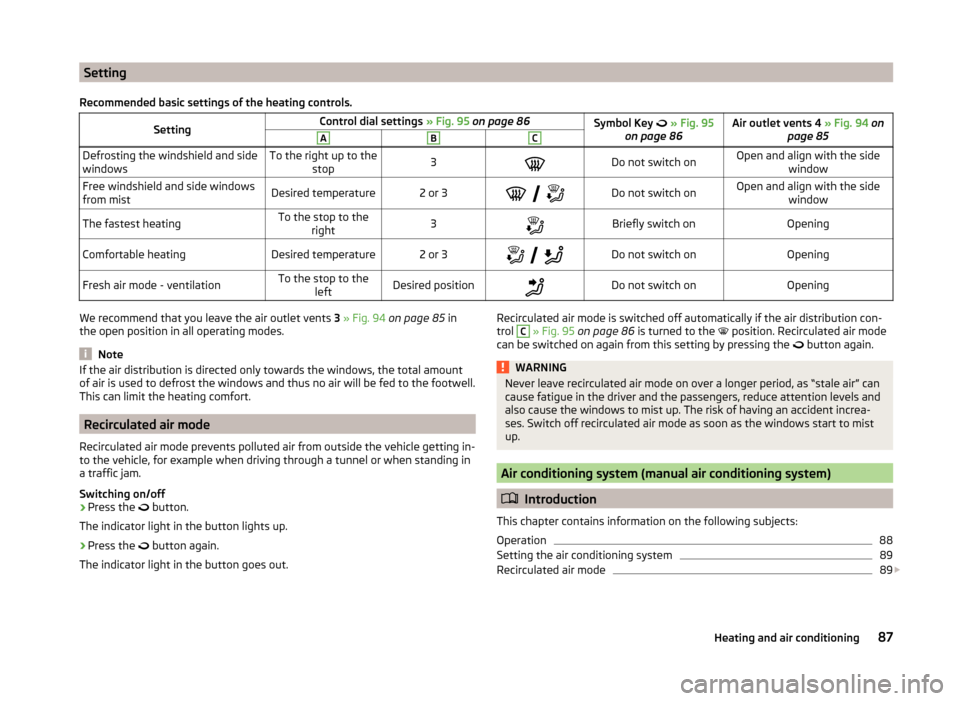
Recommended basic settings of the heating controls.SettingControl dial settings » Fig. 95 on page 86Symbol Key » Fig. 95
on page 86Air outlet vents 4 » Fig. 94 on
page 85ABCDefrosting the windshield and side
windowsTo the right up to the stop3Do not switch onOpen and align with the side windowFree windshield and side windows
from mistDesired temperature2 or 3
Do not switch onOpen and align with the side
windowThe fastest heatingTo the stop to theright3Briefly switch onOpeningComfortable heatingDesired temperature2 or 3
Do not switch onOpeningFresh air mode - ventilationTo the stop to the
leftDesired positionDo not switch onOpeningWe recommend that you leave the air outlet vents 3 » Fig. 94 on page 85 in
the open position in all operating modes.
Note
If the air distribution is directed only towards the windows, the total amount
of air is used to defrost the windows and thus no air will be fed to the footwell.
This can limit the heating comfort.
Recirculated air mode
Recirculated air mode prevents polluted air from outside the vehicle getting in-
to the vehicle, for example when driving through a tunnel or when standing in
a traffic jam.
Switching on/off
›
Press the button.
The indicator light in the button lights up.
›
Press the button again.
The indicator light in the button goes out.
Recirculated air mode is switched off automatically if the air distribution con-
trol C » Fig. 95 on page 86 is turned to the position. Recirculated air mode
can be switched on again from this setting by pressing the
button again.WARNINGNever leave recirculated air mode on over a longer period, as “stale air” can
cause fatigue in the driver and the passengers, reduce attention levels and
also cause the windows to mist up. The risk of having an accident increa-
ses. Switch off recirculated air mode as soon as the windows start to mist
up.
Air conditioning system (manual air conditioning system)
Introduction
This chapter contains information on the following subjects:
Operation
88
Setting the air conditioning system
89
Recirculated air mode
89
87Heating and air conditioning
Page 90 of 197

The cooling system operates only if the following conditions are met.The cooling system is switched on » page 88.
The engine is running.
The outside temperature is above approximately +2 °C.
The blower switch is switched on (positions 1-4).
If the desired interior temperature can also be achieved without activating the
cooling system, fresh air mode should be selected.
If the coolant temperature is too high, the cooling system is switched off to
ensure that the engine cools down.
CAUTION
■ Under certain circumstances, air at a temperature of about 5 °C can flow out
of the vents when the cooling system is switched on.■
Lengthy and uneven distribution of the air flow out of the vents (especially
around the feet) and large differences in temperature, for example, when get-
ting out of the vehicle, can cause susceptible individuals to catch a cold.
Note
■ We recommend that you have the air conditioning system cleaned by a spe-
cialist garage once every year.■
During operation of the air conditioning, under certain circumstances an in-
crease in engine idle speed may occur in order to ensure sufficient heating
comfort.
OperationFig. 96
The air conditioning system: Control elements
Read and observe
on page 88 first.
Functions of the individual controls » Fig. 96 :
Set the temperature (turn to the left: to reduce the temperature, turn to
the right: to increase the temperature)
Set the blower level (level 0: blowers off, level 4: the highest blower
speed)
Set the direction of the air outlet » page 85
Switch recirculation on/off » page 89
Switch the cooling system on/off
Note
The warning light in the symbol button lights after activation, even if not all
of the conditions for the function of the cooling system are met » page 87. The
operational readiness of the cooling system is indicated by the indicator light
in the button lighting up.ABC88Using the system
Page 91 of 197
Setting the air conditioning systemRead and observe
on page 88 first.
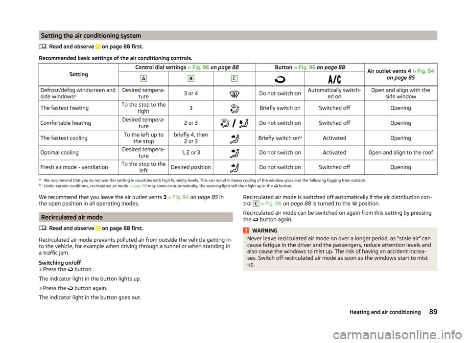
Recommended basic settings of the air conditioning controls.
SettingControl dial settings » Fig. 96 on page 88Button » Fig. 96 on page 88Air outlet vents 4 » Fig. 94
on page 85ABCDefrost/defog windscreen and
side windows a)Desired tempera-
ture3 or 4Do not switch onAutomatically switch- ed onOpen and align with theside windowThe fastest heatingTo the stop to the right3Briefly switch onSwitched offOpeningComfortable heatingDesired tempera-
ture2 or 3
Do not switch onSwitched offOpeningThe fastest coolingTo the left up to
the stopbriefly 4, then 2 or 3Briefly switch on b)ActivatedOpeningOptimal coolingDesired tempera-
ture1, 2 or 3Do not switch onActivatedOpen and align to the roofFresh air mode - ventilationTo the stop to the leftDesired positionDo not switch onSwitched offOpeninga)
We recommend that you do not use this setting in countries with high humidity levels. This can result in heavy cooling of the window glass and the following fogging from outside.
b)
Under certain conditions, recirculated air mode » page 89 may come on automatically; the warning light will then light up in the
button.
We recommend that you leave the air outlet vents
3 » Fig. 94 on page 85 in
the open position in all operating modes.
Recirculated air mode
Read and observe
on page 88 first.
Recirculated air mode prevents polluted air from outside the vehicle getting in-
to the vehicle, for example when driving through a tunnel or when standing in
a traffic jam.
Switching on/off
›
Press the button.
The indicator light in the button lights up.
›
Press the button again.
The indicator light in the button goes out.
Recirculated air mode is switched off automatically if the air distribution con-
trol C » Fig. 96 on page 88 is turned to the position.
Recirculated air mode can be switched on again from this setting by pressing the
button again.WARNINGNever leave recirculated air mode on over a longer period, as “stale air” can
cause fatigue in the driver and the passengers, reduce attention levels and
also cause the windows to mist up. The risk of having an accident increa-
ses. Switch off recirculated air mode as soon as the windows start to mist
up.89Heating and air conditioning
Page 92 of 197

Climatronic (automatic air conditioning system)
Introduction
This chapter contains information on the following subjects:
Control elements
90
Automatic mode
91
Setting the temperature
91
Recirculated air mode
91
Controlling the blower
91
Defrosting windscreen
92
Climatronic in automatic mode ensures the best-possible setting of the tem-
perature of the outflowing air, the blower stage and air distribution.
The system also takes sunlight into account, which eliminates the need to al-
ter the settings manually.
The cooling system operates only if the following conditions are met. The cooling system is switched on » page 90.
The engine is running.
The outside temperature is above approximately +2 °C.
If the coolant temperature is too high, the cooling system is switched off to
ensure that the engine cools down.
Note
■ We recommend that you have Climatronic cleaned by a specialist garage
once every year.■
During operation of the Climatronic, under certain circumstances an increase
in engine idle speed can occur in order to ensure adequate heating comfort.
Control elementsFig. 97
Climatronic: Control elements
The buttons/control dial Setting the interior temperature » page 91
Display Display of selected interior temperature
Degrees Celsius or Fahrenheit, change the displayed temperature
units » page 91
Automatic operation of the air conditioning system
Ventilation or defrosting of the windscreen activated
Direction of air flow
Recirculated air mode activated
Cooling system activated
Blower speed set
The buttons/control dial Adjust the blower speed » page 91
Interior temperature sensor Automatic mode » page 91
De-mist or de-ice the windscreen » page 92
Air flow to the windows
Air flow to the upper body
Air flow in the footwell
123456789101190Using the system
Page 93 of 197
Switch recirculation on/off » page 91
Switch the cooling system on/off
Note
Do not stick anything on or cover the interior temperature sensor 11 » Fig. 97 ;
it could have an unfavourable effect on the Climatronic system.
Automatic mode
The automatic mode is used in order to maintain a constant temperature and
to demist the windows in the interior of the car.
Switching on
›
Set a temperature between +18 °C and +29 ℃.
›
Move the air outlet vents 3 » Fig. 94 on page 85 and 4 so that the air flow is
directed slightly upwards.
›
Press the button
» Fig. 97 on page 90 ;
will appear in the display.
Automatic mode can be switched off by pressing any of the air distribution
buttons or by increasing/decreasing the blower speed. The temperature is
nevertheless regulated.
Setting the temperature
Setting temperature
›
Switch on the ignition.
›
Turn the control dial
1
» Fig. 97 on page 90 to the left or to the right to in-
crease or decrease the temperature.
Switching between Celsius and Fahrenheit
›
Press and hold the and
buttons simultaneously.
The information appears in the display in the desired temperature unit (no.
3
» Fig. 97 on page 90 ).
The interior temperature can be set between +18 °C and +29 ℃. The interior
temperature is regulated automatically within this range.
If you set the temperature below +18 ℃, “LO” appears in the display.
If you set a temperature higher than +29 ℃, “HI” appears in the display.
In both end positions, the Climatronic operates at maximum cooling or heating capacity. There is therefore no automatic temperature control.
CAUTIONLengthy and uneven distribution of the air flow out of the vents (especially
around the feet) and large differences in temperature, for example, when get-
ting out of the vehicle, can cause susceptible individuals to catch a cold.
Recirculated air mode
Recirculated air mode prevents polluted air from outside the vehicle getting in-
to the vehicle, for example when driving through a tunnel or when standing in
a traffic jam.
Switching on
›
Press the button
» Fig. 97 on page 90 .
The display shows the icon.
Switching off
›
Press the button
» Fig. 97 on page 90 again.
The icon in the display goes out.
WARNINGNever leave recirculated air mode on over a longer period, as “stale air” can
cause fatigue in the driver and the passengers, reduce attention levels and
also cause the windows to mist up. The risk of having an accident increa-
ses. Switch off recirculated air mode as soon as the windows start to mist
up.
Note
If recirculated air mode is switched on for around 15 minutes, the symbol
will begin to flash in the display as a sign that the recirculated air mode is
switched on long-term. If the recirculated air mode is not switched off, the
symbol flashes for around 5 minutes.
Controlling the blower
The Climatronic system controls the blower stages automatically in line with
the interior temperature. However, the blower level can be manually adjusted
to suit your particular needs.
›
Turn control dial
10
» Fig. 97 on page 90 to the left or to the right to increase
or decrease the blower speed.
If the blower is switched off, the Climatronic system is switched off.
91Heating and air conditioning
Page 105 of 197
WARNING■Greater physical effort is required for braking when the engine is switch-
ed off – there is the risk of an accident.■
The clutch pedal must be depressed when braking on a vehicle with man-
ual transmission, when the vehicle is in gear and at low revs. If you fail to
do so, the functionality of the brake servo can be impaired – there is the
risk of an accident.
■
If a front spoiler, full wheel trim, etc. is mounted retrospectively, it must
be ensured that the air supply to the front wheel brakes is not reduced.
The front brakes may overheat, which can have a negative impact on the
functioning of the braking system – there is a risk of an accident.
■
When leaving the vehicle, never leave persons who might, for example,
release the handbrake or take the vehicle out of gear unattended in the ve-
hicle. The vehicle might then move off – there is the risk of an accident.
CAUTION
■ Observe the recommendations on the new brake pads » page 109.■Never let the brakes slip with light pressure on the pedal if braking is not
necessary. This causes the brakes to overheat and can also result in a longer
braking distance and excessive wear.
Information for braking
Read and observe
and on page 103 first.
If the brakes are applied in full and the control unit for the braking system con-siders the situation to be dangerous for the following traffic, the brake light
flashes automatically.
After the speed was reduced below around 10 km/h or the vehicle was stop-
ped, the brake light stops flashing and the hazard warning light system
switches on. The hazard warning light system is switched off automatically af- ter accelerating or driving off again.
Before travelling a long distance down a steep gradient, reduce speed and
shift into the next lowest gear. As a result, the braking effect of the engine will
be used, reducing the load on the brakes. Any additional braking should be
completed intermittently, not continuously.
Wear-and-tear
The wear of the brake pads is dependent on the operating conditions and driv- ing style.
The brake pads wear more quickly if a lot of journeys are completed in towns and over short distances or if a very sporty style of driving is adopted.
Under these severe conditions , the thickness of the brake pads must also be
checked by a specialist garage between services.
Wet roads or road salt
The performance of the brakes can be delayed as the brake discs and brake
pads may be moist or have a coating of ice or layer of salt on them in winter.
The brakes are cleaned and dried by applying the brakes several times.
Corrosion
Corrosion on the brake discs and dirt on the bake pads occur if the vehicle has
been parked for a long period and if you do not make much use of the braking
system. The brakes are cleaned and dried by applying the brakes several times.
Faults in the brake surface
If it is found that the braking distance has suddenly become longer and that
the brake pedal can be depressed further, the brake system may be faulty.
Visit a specialist garage immediately and adjust your style of driving appropri-
ately as you will not know how great the damage is.
Low brake fluid level
An insufficient level of brake fluid may result in problems in the brake system.
The level of the brake fluid is monitored electronically » page 36,
Brake sys-
tem .
Brake booster
The brake booster increases the pressure generated with the brake pedal. The
brake booster only operates when the engine is running.103Starting-off and Driving