steering SKODA FABIA 2014 2.G / 5J User Guide
[x] Cancel search | Manufacturer: SKODA, Model Year: 2014, Model line: FABIA, Model: SKODA FABIA 2014 2.G / 5JPages: 197, PDF Size: 13.56 MB
Page 58 of 197
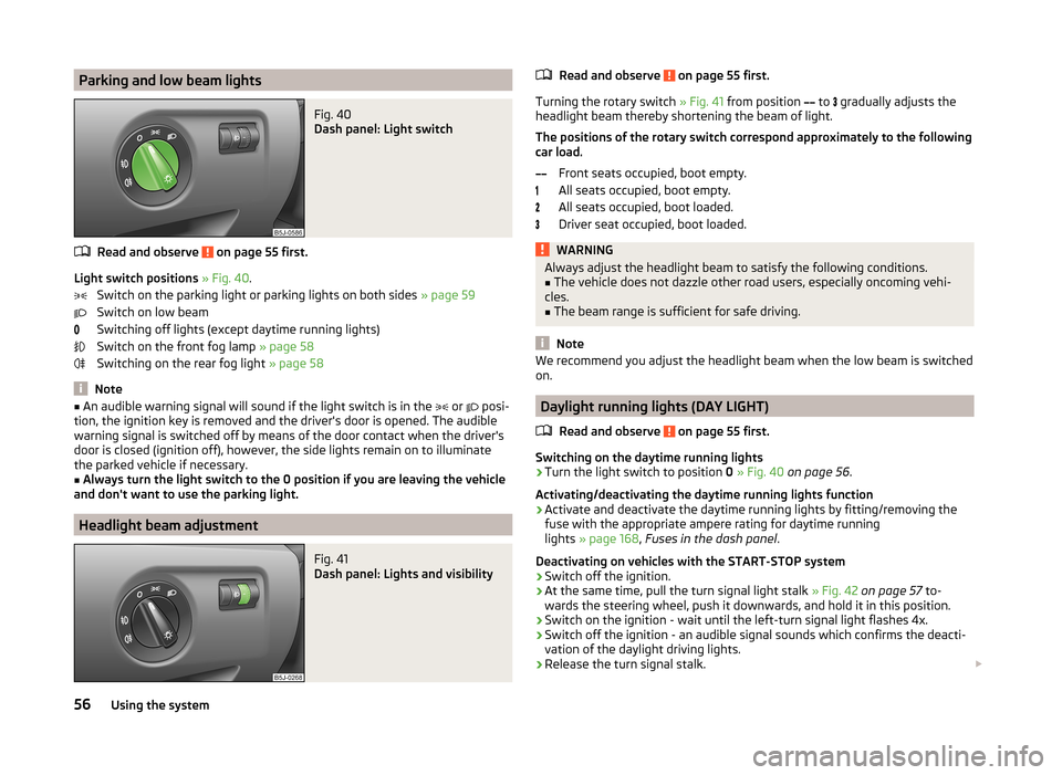
Parking and low beam lightsFig. 40
Dash panel: Light switch
Read and observe on page 55 first.
Light switch positions » Fig. 40 .
Switch on the parking light or parking lights on both sides » page 59
Switch on low beam
Switching off lights (except daytime running lights)
Switch on the front fog lamp » page 58
Switching on the rear fog light » page 58
Note
■
An audible warning signal will sound if the light switch is in the or posi-
tion, the ignition key is removed and the driver's door is opened. The audible
warning signal is switched off by means of the door contact when the driver's
door is closed (ignition off), however, the side lights remain on to illuminate
the parked vehicle if necessary.■
Always turn the light switch to the 0 position if you are leaving the vehicle
and don't want to use the parking light.
Headlight beam adjustment
Fig. 41
Dash panel: Lights and visibility
Read and observe on page 55 first.
Turning the rotary switch » Fig. 41 from position
to
gradually adjusts the
headlight beam thereby shortening the beam of light.
The positions of the rotary switch correspond approximately to the following
car load.
Front seats occupied, boot empty.
All seats occupied, boot empty.
All seats occupied, boot loaded.
Driver seat occupied, boot loaded.
WARNINGAlways adjust the headlight beam to satisfy the following conditions.■The vehicle does not dazzle other road users, especially oncoming vehi-
cles.■
The beam range is sufficient for safe driving.
Note
We recommend you adjust the headlight beam when the low beam is switched
on.
Daylight running lights (DAY LIGHT)
Read and observe
on page 55 first.
Switching on the daytime running lights
›
Turn the light switch to position 0 » Fig. 40 on page 56 .
Activating/deactivating the daytime running lights function
›
Activate and deactivate the daytime running lights by fitting/removing the
fuse with the appropriate ampere rating for daytime running
lights » page 168 , Fuses in the dash panel .
Deactivating on vehicles with the START-STOP system
›
Switch off the ignition.
›
At the same time, pull the turn signal light stalk » Fig. 42 on page 57 to-
wards the steering wheel, push it downwards, and hold it in this position.
›
Switch on the ignition - wait until the left-turn signal light flashes 4x.
›
Switch off the ignition - an audible signal sounds which confirms the deacti-
vation of the daylight driving lights.
›
Release the turn signal stalk.
56Using the system
Page 59 of 197
Activating on vehicles with the START-STOP system›Switch off the ignition.›
At the same time, pull the turn signal light stalk » Fig. 42 on page 57 to-
wards the steering wheel, push it upwards, and hold it in this position.
›
Switch on the ignition - wait until the right-turn signal light flashes 4x.
›
Switch off the ignition - an audible signal sounds which confirms the activa-
tion of the daylight driving lights.
›
Release the turn signal stalk.
On vehicles with separate lights for daylight driving lights in the fog lights or in
the front bumper, the parking lights and the licence plate light do not come on
when activating the function daylight driving lights (neither front nor rear).
If the vehicle is not equipped with separate lights for daylight driving lights,
the combination of the low beam, the parking lights (front and rear) including
the licence plate light is used as daylight driving lights.
Note
In vehicles with separate lights for daylight driving lights (in the bumper below
the main headlights) these lights also serve as side lights.
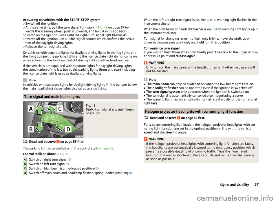
Turn signal and main beam lights
Fig. 42
Stalk: turn signal and main beam
operation
Read and observe on page 55 first.
The parking light is controlled with the control stalk » page 59.
Control stalk positions » Fig. 42 .
Switch on right turn signal
Switch on left turn signal
Switch on high beam (spring-loaded position)
Switch off main beam and headlamp flasher (spring-loaded position)
ABCDWhen the left or right turn signal is on, the
or warning light flashes in the
instrument cluster.
When the high beam or headlight flasher is on, the
warning light lights up in
the instrument cluster.
Turn signal for changing lanes - to flash only briefly, move the stalk up or
down to the pressure point only and hold it in this position.
Convenience turn signal
If you wish to flash three times only, briefly push the stalk to the upper or low-
er pressure point and release again.WARNINGOnly turn on the main beam or the headlight flasher if other road users will
not be dazzled.
Note
■ The main beam can only be switched on when the low beam lights are on.■The headlight flasher can be operated even if the ignition is switched off.■
The turn signal system only operates when the ignition is switched on.
■
The turn signal is automatically cancelled after negotiating a curve.
■
The warning light flashes at twice its normal rate if a bulb for the turn signal
light fails.
Halogen projector headlights with cornering light function
Read and observe
on page 55 first.
For a better cornering illumination, the halogen projector headlights with cor-
nering light function are set in the optimal position in line with the vehicle
speed and the steering angle.
WARNINGIf the halogen projector headlights with cornering light function are faulty,
the headlights are automatically lowered to the emergency position, which
prevents a possible dazzling of oncoming traffic. Thus the illuminated
length of the road is shortened. Drive carefully and visit a specialist garage
as soon as possible.57Lights and visibility
Page 60 of 197
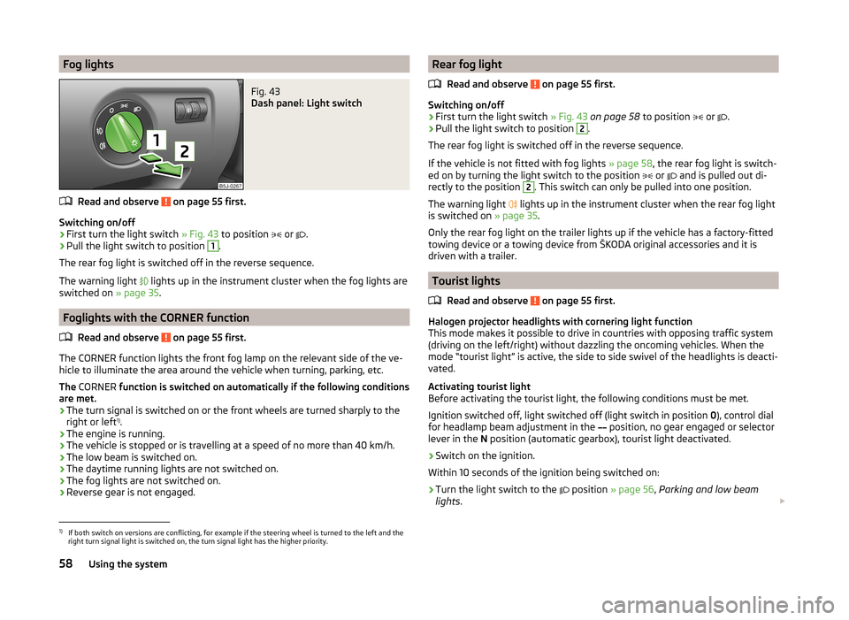
Fog lightsFig. 43
Dash panel: Light switch
Read and observe on page 55 first.
Switching on/off
›
First turn the light switch » Fig. 43 to position
or
.
›
Pull the light switch to position
1
.
The rear fog light is switched off in the reverse sequence.
The warning light lights up in the instrument cluster when the fog lights are
switched on » page 35.
Foglights with the CORNER function
Read and observe
on page 55 first.
The CORNER function lights the front fog lamp on the relevant side of the ve-
hicle to illuminate the area around the vehicle when turning, parking, etc.
The CORNER function is switched on automatically if the following conditions
are met.
› The turn signal is switched on or the front wheels are turned sharply to the
right or left 1)
.
› The engine is running.
› The vehicle is stopped or is travelling at a speed of no more than 40 km/h.
› The low beam is switched on.
› The daytime running lights are not switched on.
› The fog lights are not switched on.
› Reverse gear is not engaged.
Rear fog light
Read and observe
on page 55 first.
Switching on/off
›
First turn the light switch » Fig. 43 on page 58 to position
or
.
›
Pull the light switch to position
2
.
The rear fog light is switched off in the reverse sequence.
If the vehicle is not fitted with fog lights » page 58, the rear fog light is switch-
ed on by turning the light switch to the position
or
and is pulled out di-
rectly to the position
2
. This switch can only be pulled into one position.
The warning light lights up in the instrument cluster when the rear fog light
is switched on » page 35.
Only the rear fog light on the trailer lights up if the vehicle has a factory-fitted
towing device or a towing device from ŠKODA original accessories and it is
driven with a trailer.
Tourist lights
Read and observe
on page 55 first.
Halogen projector headlights with cornering light function
This mode makes it possible to drive in countries with opposing traffic system
(driving on the left/right) without dazzling the oncoming vehicles. When the
mode “tourist light” is active, the side to side swivel of the headlights is deacti-
vated.
Activating tourist light
Before activating the tourist light, the following conditions must be met.
Ignition switched off, light switched off (light switch in position 0), control dial
for headlamp beam adjustment in the position, no gear engaged or selector
lever in the N position (automatic gearbox), tourist light deactivated.
›
Switch on the ignition.
Within 10 seconds of the ignition being switched on:
›
Turn the light switch to the position
» page 56 , Parking and low beam
lights .
1)
If both switch on versions are conflicting, for example if the steering wheel is turned to the left and the
right turn signal light is switched on, the turn signal light has the higher priority.
58Using the system
Page 67 of 197
Seats and storage
Front seats
Introduction
This chapter contains information on the following subjects:
Adjusting the front seats - Version 1
65
Adjusting the front seats - Variant 2
65
Front seat heating
66
The driver's seat should be adjusted in such a way that the pedals can be fully
pressed to the floor with slightly bent legs.
The seat backrest on the driver's seat should be adjusted in such a way that the upper point of the steering wheel can be easily reached with slightly bent
arms.
Correct adjustment of the seats is particularly important for the following rea-
sons.
› Reaching the controls safely and quickly.
› A relaxed and fatigue-free body position.
› Achieving the maximum protection offered by the seat belts and the airbag
system.
WARNING■ Only adjust the driver's seat when the vehicle is stationary – there is the
risk of an accident.■
Caution when adjusting the seat! You may suffer injuries or bruises as a
result of adjusting the seat without paying proper attention.
■
Never carry more people than the number of seats in the vehicle.
■
Do not transport any objects on the front passenger seat other than ob-
jects (e.g. child safety seat) intended for this purpose – there is the risk of
an accident.
Note
After a certain time, play can develop within the adjustment mechanism of the
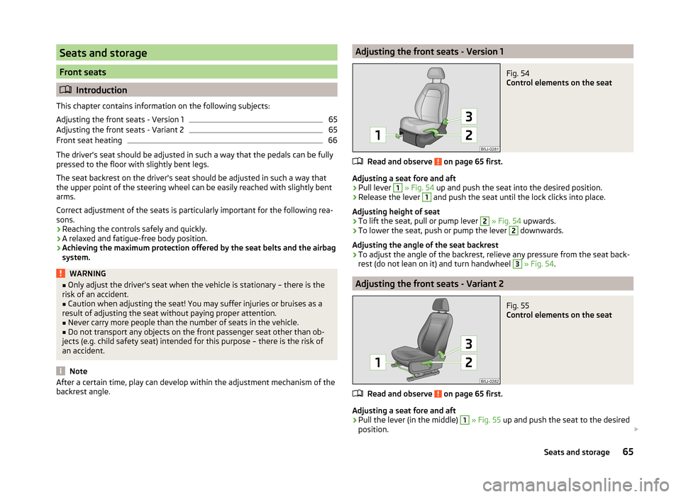
backrest angle.Adjusting the front seats - Version 1Fig. 54
Control elements on the seat
Read and observe on page 65 first.
Adjusting a seat fore and aft
›
Pull lever
1
» Fig. 54 up and push the seat into the desired position.
›
Release the lever
1
and push the seat until the lock clicks into place.
Adjusting height of seat
›
To lift the seat, pull or pump lever
2
» Fig. 54 upwards.
›
To lower the seat, push or pump the lever
2
downwards.
Adjusting the angle of the seat backrest
›
To adjust the angle of the backrest, relieve any pressure from the seat back-
rest (do not lean on it) and turn handwheel
3
» Fig. 54 .
Adjusting the front seats - Variant 2
Fig. 55
Control elements on the seat
Read and observe on page 65 first.
Adjusting a seat fore and aft
›
Pull the lever (in the middle)
1
» Fig. 55 up and push the seat to the desired
position.
65Seats and storage
Page 78 of 197
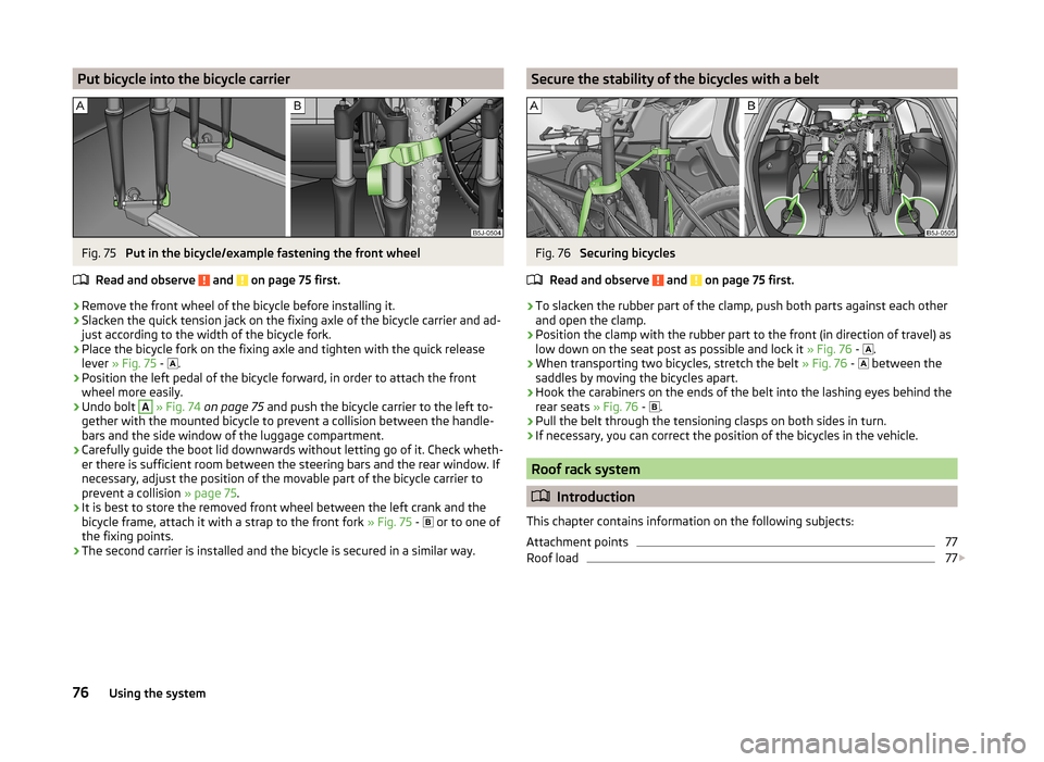
Put bicycle into the bicycle carrierFig. 75
Put in the bicycle/example fastening the front wheel
Read and observe
and on page 75 first.
›
Remove the front wheel of the bicycle before installing it.
›
Slacken the quick tension jack on the fixing axle of the bicycle carrier and ad-
just according to the width of the bicycle fork.
›
Place the bicycle fork on the fixing axle and tighten with the quick release
lever » Fig. 75 -
.
›
Position the left pedal of the bicycle forward, in order to attach the front
wheel more easily.
›
Undo bolt
A
» Fig. 74 on page 75 and push the bicycle carrier to the left to-
gether with the mounted bicycle to prevent a collision between the handle-
bars and the side window of the luggage compartment.
›
Carefully guide the boot lid downwards without letting go of it. Check wheth-
er there is sufficient room between the steering bars and the rear window. If
necessary, adjust the position of the movable part of the bicycle carrier to
prevent a collision » page 75.
›
It is best to store the removed front wheel between the left crank and the
bicycle frame, attach it with a strap to the front fork » Fig. 75 -
or to one of
the fixing points.
›
The second carrier is installed and the bicycle is secured in a similar way.
Secure the stability of the bicycles with a beltFig. 76
Securing bicycles
Read and observe
and on page 75 first.
›
To slacken the rubber part of the clamp, push both parts against each other
and open the clamp.
›
Position the clamp with the rubber part to the front (in direction of travel) as
low down on the seat post as possible and lock it » Fig. 76 -
.
›
When transporting two bicycles, stretch the belt
» Fig. 76 -
between the
saddles by moving the bicycles apart.
›
Hook the carabiners on the ends of the belt into the lashing eyes behind the
rear seats » Fig. 76 -
.
›
Pull the belt through the tensioning clasps on both sides in turn.
›
If necessary, you can correct the position of the bicycles in the vehicle.
Roof rack system
Introduction
This chapter contains information on the following subjects:
Attachment points
77
Roof load
77
76Using the system
Page 94 of 197
The blower speed set is indicated by displaying the corresponding number of
segments in icon 9 » Fig. 97 on page 90 in the display.WARNING■
“Stale air” may result in fatigue in the driver and occupants, reduce atten-
tion levels and also cause the windows to mist up. The risk of having an ac-
cident increases.■
Do not switch off the Climatronic system for longer than necessary.
■
Switch on the Climatronic system as soon as the windows mist up.
Defrosting windscreen
Switching on
›
Press the button
» Fig. 97 on page 90 .
Switching off
›
Press the button
» Fig. 97 on page 90 again or press the
button.
More air flows out of the air outlet vents 1 and 2 » Fig. 94 on page 85 . The
temperature control is controlled automatically.
Communication and multimedia
Universal telephone preinstallation GSM II
Introduction
This chapter contains information on the following subjects:
Mobile phones and two-way radio systems
92
Introductory information
93
Phone Phonebook
93
Operating the phone on the multifunction steering wheel
94
Inserting the mobile phone and adapter
94
Managing telephone calls with the help of the adapter
95
Connecting the mobile phone to the hands-free system
95
Symbols in the MAXI DOT display
96
Telephone operation in the MAXI DOT display
96
Mobile phones and two-way radio systems
ŠKODA permits the operation of mobile phones and two-way radio systems
with a professionally installed external aerial and a maximum transmission
power of up to 10 watts.
Please consult a ŠKODA Partner for information about the possibility of instal- ling and operating mobile phones and two-way radio systems with a transmis-
sion power of more than 10 W.
Operating mobile phones or two-way radio systems may interfere with the
functionality of the electronic systems in your vehicle.
The possible reasons for this are.
› no external aerial.
› external aerial incorrectly installed.
› transmission power greater than 10 watts.
WARNING■
Concentrate fully at all times on your driving! As the driver, you are fully
responsible for the operation of your vehicle.■
Only use the device in a way that you are in full control of your vehicle in
every traffic situation – there is the risk of accidents!
92Using the system
Page 95 of 197
WARNING (Continued)■The national regulations for using a mobile phone in a vehicle must be
observed.■
If a mobile phone or a two-way radio system is operated in a vehicle with-
out an external aerial or an external aerial which has been installed incor-
rectly, this can increase the strength of the electromagnetic field inside the
vehicle.
■
Two-way radio systems, mobile phones or mounts must not be installed
on airbag covers or within the immediate deployment range of the airbags.
■
Never leave a mobile phone on a seat, on the dash panel or in another
area, from which it can be thrown during a sudden braking manoeuvre, an
accident or a collision - risk of injury.
■
The Bluetooth ®
function must be switched off by a specialist workshop
before the vehicle is transported by air.
Note
■ We recommend that mobile phones and two-way radio systems be installed
in the a vehicle by a specialist workshop.■
Not all mobile phones that enable Bluetooth ®
communication are compatible
with the universal telephone preinstallation GSM II. You can ask a ŠKODA Part-
ner whether your telephone is compatible with the GSM II universal telephone
fitting.
■
The range of the Bluetooth ®
connection to the hands-free system is restric-
ted to the vehicle interior. The range is dependent on local factors, e.g. obsta-
cles between the devices and mutual interferences with other devices. If your
mobile phone is in a jacket pocket, for example, this can lead to difficulties
when establishing a connection with the hands-free-system or transferring
data.
Introductory information
The universal telephone preinstallation GSM II (hands-free system) includes a
convenience mode for the mobile phone via voice control, the multifunction
steering wheel, the adapter, radio or the navigation system.
The universal telephone preinstallation GSM II comprises the following func-
tions.
› Phone Phonebook
» page 93.
› Convenience operation of the telephone via the multifunction steering
wheel » page 94 .
›Managing telephone calls via the adapter
» page 95.
› Telephone operation in the MAXI DOT display
» page 96.
› Voice control of the telephone
» page 97.
› Music playback from the telephone or other multimedia units
» page 98.
All communication between a mobile phone and your vehicle's hands-free sys-
tem is established with the help of Bluetooth ®
technology. The adapter serves
only for charging the telephone and for transmitting the signal to the vehicle's
external aerial.
Note
The following guidelines must be observed » page 92, Mobile phones and two-
way radio systems .
Phone Phonebook
A phone phonebook is part of the hands-free system. This phone phonebook
can be used depending on the type of mobile phone.
After the first connection of the telephone, the system begins to load the
phone book from the phone and the SIM card into the memory of the control
unit.
Each time the telephone has established a new connection with the hands-
free system, an update of the relevant phone book is performed. The updating
can take a few minutes. During this time the phone book, which was stored af-
ter the last update was completed, is available. Newly stored telephone num-
bers are only shown after the updating has ended.
The update is interrupted if a telephone event (e.g. incoming or outgoing call,
voice control dialogue) occurs during the updating procedure. After the tele-
phone event has ended, the updating starts anew.
The internal phonebook provides 2 500 free memory locations. Each contact can contain up to 4 numbers.
If the number of contacts loaded exceeds 2 500, the phone book is not com-
plete.
93Communication and multimedia
Page 96 of 197
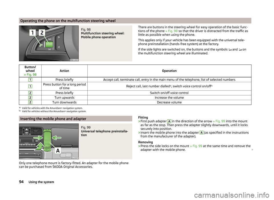
Operating the phone on the multifunction steering wheelFig. 98
Multifunction steering wheel:
Mobile phone operation
There are buttons in the steering wheel for easy operation of the basic func- tions of the phone » Fig. 98 so that the driver is distracted from the traffic as
little as possible when using the phone.
This applies only if your vehicle has been equipped with the universal tele-
phone preinstallation (hands-free system) at the factory.
If the side lights are switched on, the buttons and the symbols
and
on
the multifunction steering wheel are illuminated.Button/ wheel
» Fig. 98ActionOperation
1Press brieflyAccept call, terminate call, entry in the main menu of the telephone, list of selected numbers1Press button for a long period of timeReject call, last number dialled a)
, switch voice control on/off b)2Press brieflySwitch on/off voice control2Turn upwardsIncrease the volume2Turn downwardsDecrease volumea)
Valid for vehicles with the Amundsen+ navigation system.
b)
Valid for vehicles without the Amundsen+ navigation system.
Inserting the mobile phone and adapterFig. 99
Universal telephone preinstalla-
tion
Only one telephone mount is factory-fitted. An adapter for the mobile phone
can be purchased from ŠKODA Original Accessories.
Fitting›First push adapter A in the direction of the arrow » Fig. 99 into the mount
as far as the stop. Then press the adapter slightly downwards, until it locks
securely into position.›
Insert the mobile phone into the adapter
A
(as specified in the instructions
from the manufacturer of the adapter).
Removing
›
Press the side locks on the mount » Fig. 99 at the same time and remove the
adapter with the mobile phone.
94Using the system
Page 99 of 197
Bluetooth
The following menu items can be selected from the Bluetooth menu item.
■ User - Overview of the stored users
■ New user - Search for new mobile phones in reception range
■ Visibility - Switches on the visibility of the phone for other devices
■ Media Player
■ Active device
■ Paired devices
■ Search
■ Phone name - option to change the name of the phone (default SKODA_BT)
Settings
The following menu items can be selected from the Settings menu item.
■ Phone book
■ Update 1)
■ List
■ Surname
■ First name
■ Ring tone
Back
Return in the Start menu of the telephone.
Voice control
Introduction
This chapter contains information on the following subjects:
Dialogue
97
Voice commands
98
Dialogue
The period of time during which the system is ready to receive voice com-
mands and to carry them out is called a dialogue. The system gives audible
feedback and guides you if necessary through the relevant functions.
Optimum understanding of the voice commands depends on several factors.
› Speak with a normal tone of voice without intonation and excessive pauses.
› Avoid a bad pronunciation.
› Close the doors, windows and sliding roof, to reduce or stop disturbing exte-
rior noise.
› It is recommended to speak louder at higher speeds, so that the tone of your
voice is louder than the increased surrounding noise.
› During the dialogue, limit additional noise in the vehicle, e.g. passengers talk-
ing at the same time.
› Do not speak, if the system makes an announcement.
The microphone for voice control is inserted in the moulded headliner and di-
rected to the driver and front passenger. Therefore the driver and the front
passenger can operate the equipment.
Entering a phone number
The telephone number can be entered as a continuous series of individually
spoken digits (the whole number at once) or in the form of digital blocks (sepa-
rated by short pauses). After each order of digits (separation through brief
voice pause) all of the digits detected up to now are repeated by the system.
The digits 0 - 9, symbols +,
, #
are permitted. The system detects no continu-
ous digit combinations such as twenty-three, but only individually spoken dig-
its (two, three).
Switching on voice control
› Press the
button on the adapter
» Fig. 100 on page 95 briefly.
› Press the
1
button on the multifunction steering wheel briefly
» page 94,
Operating the phone on the multifunction steering wheel .
Switching off voice control
If the system is currently playing a message, the message that is currently be-
ing played will have to be stopped as follows:
› Press the
button on the adapter briefly.
› Press the
1
button on the multifunction steering wheel briefly.
If the system is expecting a voice command, you can end the dialogue yourself
as follows.
› with the
CANCEL voice command.
› Press the
button on the adapter.
› Press the
1
button on the multifunction steering wheel briefly.
1)
On vehicles fitted with the Amundsen+ navigation system, this function can be accessed via the naviga-
tion system menu; refer to the » Operating instructions for the Amundsen+ navigation system .
97Communication and multimedia
Page 100 of 197
Note■The dialogue of an incoming call is immediately interrupted.■The voice control is only possible in vehicles fitted with a multifunction
steering wheel with telephone control or a phone mount and adapter.
Voice commands
Basic voice commands
Voice commandActionHELPAfter this command the system repeats all possible
commands.CALL XYZThis command calls up the contact from the phone
book.PHONE BOOKAfter this command, for example, the phone book
can be repeated back to you, a voice entry for the
contact can be updated or deleted, etc.CALL REGISTERLists of dialled numbers, missed calls, etc.DIAL NUMBERAfter this command, a telephone number can be
entered to establish a connection with the reques-
ted party.REDIALAfter this command the system calls the last dial-
led number.MUSIC a)Play music from the mobile phone or another
paired device.FURTHER OPTIONSAfter this command the system offers additional
context-dependent commands.SETTINGSSelection for setting Bluetooth ®
, dialogue etc.CANCELThe dialogue is ended.a)
On vehicles fitted with the Amundsen+ navigation system, this function can be accessed via the naviga-
tion system menu; refer to the » Operating instructions for the Amundsen+ navigation system .
If a voice command is not detected, the system answers with “ Sorry?”, and a
new attempt can be made. After the 2nd error the system repeats the aid. Af-
ter the 3rd attempt the answer “ Cancelled” is given and the dialogue is ended.
Store voice recording of a contact
If automatic name recognition does not work reliably for some contacts, you
can choose to save your own voice tag for the contact in the Phone book -
Voice tag - Record menu item.
Your own voice tag can also be saved using the voice control in the FURTHER
OPTIONS menu.
Multimedia
Introduction
This chapter contains information on the following subjects:
Music playback via Bluetooth ®
98
Operating the radio and navigation system on the multifunction steering
wheel
99
AUX and MDI inputs
99
Music playback via Bluetooth ®
The universal telephone preinstallation GSM II makes it possible to play back
music via Bluetooth ®
from the devices such as MP3 player, mobile phone or
notebook.
To ensure the music can be played back via Bluetooth ®
, you must first pair the
device with the hands-free system in the Phone - Bluetooth - Media player
menu.
The music playback process is performed on the connected device.
The universal telephone preinstallation GSM II ensures that the music played
back via the hands-free system can be controlled with the remote con-
trol » page 98 , Voice commands .
Note
The device being connected must support the Bluetooth ®
A2DP profile; refer
to the operating instructions for the relevant device being connected.98Using the system